Charge Controller isn't outputting enough voltage for Lithium Battery... maybe.

I just setup my controller and such last night and got my Renogy lithium battery today. Before connecting the panels, I programmed my controller with parameters that I thought would work, but it doesn't seem to be. At least it's not behaving how I expected.
In short, It's "charging" right now, but my multimeter only reads 13.2V on the battery. My little $18 inline shunt meter reads 13.35V. The controller meter says 13.4V. It's been charging for an hour. If I disconnect the panels and then the battery (both are on cutoff switches), and I read the voltage again (with no charging or discharging at all), it still just reads 13.2V. If it were truly charging the battery, then the voltage would be higher when charging than idle, but they are both the same.
Here's what the controller meter shows:

I'd assume that amperage reading in the middle indicates that it's putting 3.9A into the battery, but maybe that only means what's available.
My only background regarding battery charging is with cars, plus hours of research on here and other forums about solar charging FLA batteries. That's not really applicable with Lithium batteries, so maybe I don't know as much as I need to.
When your alternator runs, it's putting 14+ volts on the battery because that's the only way to get current to flow into it. It has to significantly exceed the battery's voltage. I'd assume the same is true of lithium batteries, so how can it be charging the battery at only 13.4V?
One might assume that maybe it's in float charge mode if the battery is full, but I have the float charge set to 14.4V, so that doesn't make any sense. Renogy just says to charge it at 14.4V +/- 0.2. It says nothing about float, and my research says that it's just supposed to be the same as the charging voltage. The internal BMS will use that voltage as needed to balance cells, etc. Internally, it manages what it actually uses, and whether it truly "floats" at all. It also says it will cutoff charging above 14.6V, which I assume is a safety mechanism. It doesn't want to receive any more than that.
My hardware:
Controller: EPEVER MPPT Solar Charge Controller 50A 150V
Meter: MT50 Remote Meter
Battery: Renogy 12V 170 Ah (RNG-BATT-LFP-12-170)
Here is a photo of all of the settings the controller lists in the manual:

First off. I don't understand all of these settings. I've read other posts on these forums and searched the web, but I still came up short.
Over voltage disconnect voltage - I'm guessing this means that if the controller will disconnect if the detected battery voltage is higher than the value. And then reconnect when it's equal to or lower than the "Over voltage reconnect voltage". I'm not really sure what this feature is for. An FLA battery itself could never output 16V, right? So what does this feature do, and why is the number so high for those types of batteries? I set this value to 14.5, and the reconnect to 14.3, but I have no idea if that's right.
Charging limit voltage - I set this to 14.4. I suppose it could be 14.5, or maybe even 14.6 if the battery cuts off above 14.6V, but I figured setting it to 14.4 is best. I figure this is the absolute highest voltage the controller will send to the batteries.
Equalize charging voltage - not really applicable to LFP batteries, but I set it to 14.4 to effectively disable it. I also set "Equalize duration" to 0.
Boost charging voltage - Is this the same as "Absorption"? I set it to 14.4V
Float charging voltage - Like I said above, I've read it's supposed to be the same as the main charging voltage, so I set it to 14.4V.
Boost reconnect charging voltage - Really not sure on this one. It seems like the voltage it must drop to in order to go back into boost/absorption mode? I could have that totally wrong. It won't let me set it to 14.4; it gives me a parameter error. It defaulted to 13.2. I could set it to 14.2, but that didn't change the behavior of the controller.
Low Voltage Reconnect voltage - I believe this is only used when using the Load side of the controller for lights and other small appliances. The thing is, my model of controller doesn't even have load connections. [EDIT: I'm wrong, it totally has load connections, but I'm probably never going to use them.] I believe if the battery goes below the "Low voltage disconnect voltage", it will cutoff the load, and only reconnect when the battery is back above the reconnect voltage. Seems pointless to bother with these settings, but I set them at rational values. The battery will internally cut itself off at 10V, so I set the disconnect at 11, and the reconnect at 12.
Under voltage warning - I'm assuming this means it will audibly beep and turn on the warning LED if the voltage drops below this value, giving you a chance to deal with the issue. I set it to 11V and the "reconnect" to 11.2.
Discharging limit voltage - Seems like it might be for the load again. Not sure how this differs from the low voltage disconnect.
Boost duration - Seems moot if I set the boost voltage to the same as the charge limit voltage, but I left it at the default of 120 minutes. I'm assuming this is the duration of absorption charging, after which is will enter float charging.
If I'm wrong about the meanings of any of these, please illuminate me! I don't just want to know what settings to use; I want to understand what these things mean. But, primarily, I need to know how to get this thing to actually charge my battery!
Comments
-
There's only one amp coming in from your panel(s). If you've mentioned what panel you are using I missed it. So why are you only getting one amp from your panel(s)?
2.1 Kw Suntech 175 mono, Classic 200, Trace SW 4024 ( 15 years old but brand new out of sealed factory box Jan. 2015), Bogart Tri-metric, 460 Ah. 24 volt LiFePo4 battery bank. Plenty of Baja Sea of Cortez sunshine.
-
It's partly cloudy where I am, and they're not tilted. I have three Renogy 100W panels in series. I own six total, but I'm just testing with three. This is for an RV.
Regardless of the current from the panels, the voltage is plenty high, and the MPPT controller will trade one for the other as needed. But why is it only outputting 13.4V?
EDIT: I just found some of the deeper monitor screens of the meter, specifically for the battery. It claims to be in Boost mode, but that makes no sense given the low voltage.
-
I'm not an expert on lithium batteries but I'd guess they are sitting at 13.4 and the small amount of current isn't sufficient to charge them very fast. Batteries dictate the charging voltage which the controller is stepping down to. You can shut down the controller then reconnect the next time the sun is overhead and shining brightly on your panels. Then you should see substantial current . You're only getting 53 watts from your 300 watts of panels. The 53 volts mean very little at one amp of current.
2.1 Kw Suntech 175 mono, Classic 200, Trace SW 4024 ( 15 years old but brand new out of sealed factory box Jan. 2015), Bogart Tri-metric, 460 Ah. 24 volt LiFePo4 battery bank. Plenty of Baja Sea of Cortez sunshine.
-
What do you mean by, "Batteries dictate the charging voltage which the controller is stepping down to."? Are you saying that that battery itself is somehow telling the controller what voltage to send? That doesn't make any sense to me.
The amperage the controller is outputting is moot if the voltage isn't high enough. If the voltage were 14.4 with 0.5A, it works still charge the battery, albeit very slowly. I saw the another as high as 5 amps, but the voltage was still only 13.2 at the battery. I don't see why that should be the case with the settings I chose.
-
At that voltage, the battery is 90 to 95% full. The battery is restricting the voltage rise. 3.9 amps is not enough amperage to push the battery voltage up very quickly. 3.9 amps is only a 2.29% charge rate. So that would indicate that the PV input power is to low to drive the battery voltage up faster. Also, I recommend the float voltage be set at 13.4 volts.
Rick
4480W PV, MNE175DR-TR, MN Classic 150, Outback Radian GS4048A, Mate3, 51.2V 360AH nominal LiFePO4, Kohler Pro 5.2E genset. -
So, for a proper test, I should run a load on this battery for a while and try my testing again, tomorrow? I guess I didn't expect them to send me a battery with such a high SoC. I also didn't realize the battery could prevent the controller from stepping up the voltage. Any thoughts you could add about how that works would be greatly appreciated.
Regarding the float voltage, what's the reason to lower it? I really want to understand this stuff and not just make changes without understanding them.
-
All batteries have some resistance to charging, and LFP batteries are no exception. This is overcome by increasing amperage. The higher the charging amperage the higher it will push the voltage of the battery. However there is a maximum amount of amps that can be applied to a battery determined by the Battery chemistry, size and voltage. This information should be available from the battery manufacturer. Example, if a battery is at a lower state of charge and the maximum amperage is applied, the voltage will go to absorb voltage almost immediately and stay there until absorb is finished. If a charge of half that amount is applied to the same battery, the voltage will rise, but take much more time to reach absorb voltage. The lower the charging amps the longer it will take to reach absorb voltage.
LFP batteries do not like sitting at 100% state of charge, 90% SOC is the max generally preferred. Actually, they really never need to go to 100% unless they are balanced by a BMS at that point, which is the case for Renogy LFP batteries. These batteries really only need to reach 100% periodically so no worry about going even weeks without reaching float.
Rick
4480W PV, MNE175DR-TR, MN Classic 150, Outback Radian GS4048A, Mate3, 51.2V 360AH nominal LiFePO4, Kohler Pro 5.2E genset. -
The internal resistance of this battery is "<30 milliohms". I don't think that's a significant factor. If the voltage were high enough, the battery would receive a charge, regardless of the amount of current. That's how trickle chargers work. You can buy ones that go as low as 0.75A, yet they still charge a battery because they are outputting 14+ volts. It's the voltage that forces the current to flow in a certain direction, from high voltage to low.
Are you sure you don't have current and voltage backwards? Voltage is what is metaphorically called the "pressure" and the current is the flow rate, but you are saying that the current is "pushing the voltage". That seems backwards to me.
-
It may sound obtuse, but you will see, with experience, that's the way it works. I've had a 200 amp hour LFP battery bank in service for almost 3 years and what I have described is the charging characteristics I've observed. Watch the charging voltage the next time you have some good direct sun on your three 100 watt panels. That should give you about 12 charging amps. Even that is only about a 6% charge rate. Hopefully it will raise the battery voltage 1 or 2 tenths of a volt.
Rick
4480W PV, MNE175DR-TR, MN Classic 150, Outback Radian GS4048A, Mate3, 51.2V 360AH nominal LiFePO4, Kohler Pro 5.2E genset. -
I'm NOT a lithium battery expert, far from it, but one of the advantages of lithium batteries is that they are VERY efficient, They don't require the much higher voltage you see with lead acid batteries. Small differences in voltage may be within the tolerances of the meters in use, though the voltage on the charge controller should represent what it's putting out.
As it is approaching full, I'd relax and see what happens on a sunny day.
Home system 4000 watt (Evergreen) array standing, with 2 Midnite Classic Lites, Midnite E-panel, Magnum MS4024, Prosine 1800(now backup) and Exeltech 1100(former backup...lol), 660 ah 24v Forklift battery(now 10 years old). Off grid for 20 years (if I include 8 months on a bicycle).
- Assorted other systems, pieces and to many panels in the closet to not do more projects. -
@Rick
I guess my misunderstanding may result from not understanding solar controllers, or maybe LFP batteries. It would mean a lot if anyone could point out anything I get wrong in this reply.
A car battery is 12.6V. You use maybe 5% charge to start your engine, and then the alternator starts charging it. If you read the battery before starting it, it will say 12.6V. If you read it while it's charging, it will read 14.7V because that's what the alternator is putting out. At that point you're not reading the battery, you're reading the alternator, even at the battery terminals. It's all the same circuit and there's no way to read the battery in isolation. You're reading the current voltage on the wire, and it's the 14.7. That's what it needs to put out in order to get current to flow into the battery. It's high because lead acid batteries have a lot of internal resistance and all that. I get that. But the voltage is a constant except for more modern alternators that taper it off. If it were a simpler design, the RPM of the alternator is what determines the voltage. The battery's voltage before it started has no effect on the reading you get with the multimeter while the alternator is running. It could have been 10, 12, or even 13, and it would still read 14.7V with the alternator running.
Now, with solar, I guess I was expecting the same thing to happen. The battery reads 13.2 volts. When the sun was out in full, I turned on the panels... and the voltage at the terminals still reads 13.2 V, yet the controller now says it's putting out 5 A. How can that be? How can those 5 amps be getting into the battery if the voltage hasn't changed? And why doesn't it read 14.4V since that's what I configured it to output? I would not expect the voltage to slowly climb to what would indicate a 100% SoC. I would expect it to read 14.4V immediately. Only when disconnecting the panels would I expect it to read the battery's voltage itself, since the controller would no longer be outputting anything.
Obviously, a solar controller is is a lot more complex than an alternator, but this one doesn't understand anything about LFP batteries. All it has is a list of voltages you configure, and some preset ones for Sealed, AGM, and Flooded. Regardless of the state of charge of the battery, the controller should be putting out the configured voltage for the configured stage of charging... Right? And while it's doing that, your multimeter on the battery terminals should read that voltage. Yes? It said it was in Boost mode, and that's configured for 14.4V. Being an MPPT controller, it should have no trouble dropping the current a little to make it be 14.4V. It had 67W to work with.
Now, if I used the same settings but I connected a flooded battery, there's no way it would have charged it. The controller was supposedly in Boost (absorb) mode, but the voltage was less than a traditional float charge by almost half a volt. I'm just not understanding why that was the case. The whole puzzle of what's going on just doesn't fit together. It just feels like the controller is misbehaving.
I was getting some direct sun. It was partly cloudy. Yet even after 2 hours of leaving it running (with untilted panels) in the mixed sun and clouds, a multimeter at the terminals never read more than that 13.2. It changed up and down slightly. In fact, at the end it was even lower. Like 13.16.
-
The higher the current available, the faster the voltage will climb is I believe what was meant, however with Lifepo4 as the voltage nears the knee in the charging curve, the BMS will limit the current to prevent individual cell voltage runaway. The charging requirements are very different from that of lead acid where cell voltage differential is of less concern, with Lifepo4 it's very important to keep the cell voltages close to one another. Since the cells are not accessible it's not possible in your case to measure individual cell voltage, the reading of the cells in series is the only indication of state of charge, however a meter with 1000mV or 0.1V resolution is not accurate enough because 13.4V indicated could be 13.351V for example or it could be 13.499V.
When the battery was assembled the cells would have been ballanced, the ballancing the BMS dose at 14.4V is at extremely low current values which some meters may not be able to detect and definitely not the controller display. In reality once the cells are accurately ballanced the is little need to perform ballancing on a daily basis. With a DIY bank it's possible to monitor individual cells to visually see what's going on, however with a packaged bank this is not possible.
The BMS I have has a recommended input of 28.8V (24V nominal system ) constant voltage which is in the ballance regon, I however use 28.0V to avoid unnecessary time in that regon, the actual battery voltage never goes over 27.4V before transition to float 27V. After 6 months of daily discharge of ~25%, I reset it to 28.8V to see how in ballance the cells were, there was negligible change. The manufacturer of a sealed battery has no knowledge of what the end users abilities or knowledge, so they supply a recommended set of values. The question of the use of 28.8V as a setting was asked to both the battery manufacturer and BMS manufacturer I purchased from, both said that that was normal.
Since there is very little useful capacity over 3.400V per cell there is little point in reaching that value. One manufacturer of a battery system states that if the charge settings are set at 3.600V per cell, rather than 3.400V, the warranty is reduced from 10 to 5 years, there is also a maximum discharge parameter of 20% SOC involved. This also seem to be the general consensus wit of grid users of lifepo4 prysmatic cells which may differ from your battery if it uses hundreds of small cells though I do have my doubts.
Just a collection of thoughts which may or may not be helpful
1500W, 6× Schutten 250W Poly panels , Schneider MPPT 60 150 CC, Schneider SW 2524 inverter, 400Ah LFP 24V nominal battery with Battery Bodyguard BMS
Second system 1890W 3 × 300W No name brand poly, 3×330 Sunsolar Poly panels, Morningstar TS 60 PWM controller, no name 2000W inverter 400Ah LFP 24V nominal battery with Daly BMS, used for water pumping and day time air conditioning.
5Kw Yanmar clone single cylinder air cooled diesel generator for rare emergency charging and welding. -
I expect you need a more precise volt meter. Let's say the battery has .010 ohms internal resistance. And you are charging with 5A. Volts = current * resistance, so I'd expect to see a .05V rise in terminal voltage when charging (lead acid batteries are different here).
> I would expect it to read 14.4V immediately
That would cause input power to your battery to exceed your solar power, which is impossible. So the voltage drops as needed. In other words, when you set 14.4V on a charge controller, it actually means "14.4V or the voltage needed to limit power output to the available input power, whichever is lower".
Keep charging and eventually you will see a good voltage rise.
I am available for custom hardware/firmware development
-
Try to look at it as if the battery were a load on the charge controller. If the battery needs more amps than the charge controller can supply then the voltage will drop. The charge controller's actual output is still 14.4 volts, but the load that the battery is putting on it is dragging the voltage down.
4480W PV, MNE175DR-TR, MN Classic 150, Outback Radian GS4048A, Mate3, 51.2V 360AH nominal LiFePO4, Kohler Pro 5.2E genset. -
@Raj174 Interesting. At what point will the battery not need more amps? The very end of the charge cycle when it's very nearly full? At that point, I might actually see 14.4V then? Or will it always be lower than that?
Looking at the following graph from Battery University, the voltage only increases during the bulk charging phase, and stays flat during the saturation (absorption) phase. So am I always going to see a max of ~13.4V when charging?
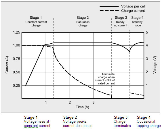
Source: https://batteryuniversity.com/learn/article/charging_lithium_ion_batteries
Regarding float voltage, you never mentioned the reasoning behind your recommendation. If the internal BMS manages what they battery takes in, why lower the voltage at all? I'm curious what Renogy says it should be. I'm not finding anything so far.
-
Correct, it will take amps until it is full. The battery will take constant current until the voltage reaches the absorb set point and then because the voltage will no longer rise, the amperage will begin to slowly drop while the voltage remains constant. With solar charging, charging amps are usually less than the max the battery will take, especially with LFP batteries, so the voltage will slowly rise to about 80 to the low 90s% before they reach absorb voltage. This is a screen capture of my charge controller charging my bank on a typical sunny day. You will notice the voltage (yellow line) rises through the day until it reaches the absorb set point in the afternoon at 3:33 PM and then holds steady there until 4:00 PM, then the charge controller goes to rest (not charging) until the battery discharges to the float set point. At that time the charger begins charging at float voltage. This is roughly a 24 hour period.
The reason a battery is not floated at absorb voltage is that it shortens the life of the battery. In other words, it ages the cells unnecessarily.
Rick
 4480W PV, MNE175DR-TR, MN Classic 150, Outback Radian GS4048A, Mate3, 51.2V 360AH nominal LiFePO4, Kohler Pro 5.2E genset.
 -
The image is not the charging curve for lifepo4, which is what you have. The current should be at maximum until almost fully charged, it should then cascade to very low values as it approaches the terminal voltage set-point, 14.4V in your case. Because this is the ballancing portion it may take hours, days, weeks or even years to achieve perfect balance, depending on capacity, how out of ballance the cells are and the ballance current capabilities. Here is the curve for a 180 Ah prysmatic cell, note the current relationship to voltage, this is for a single cell, multiply by 4 for 12V nominal
 1500W, 6× Schutten 250W Poly panels , Schneider MPPT 60 150 CC, Schneider SW 2524 inverter, 400Ah LFP 24V nominal battery with Battery Bodyguard BMS
Second system 1890W 3 × 300W No name brand poly, 3×330 Sunsolar Poly panels, Morningstar TS 60 PWM controller, no name 2000W inverter 400Ah LFP 24V nominal battery with Daly BMS, used for water pumping and day time air conditioning.
5Kw Yanmar clone single cylinder air cooled diesel generator for rare emergency charging and welding. -
Well I missed out on a lot of much more detailed explanation on lithium batteries than I could give.
As to your question for me. If the battery is sitting at 13.4 volts the charge controller is going to supply charging voltage which when connected to the battery will basically be a bit higher than the batteries voltage. Voltage, up to the absorb voltage is available but the battery doesn't instantly jump to absorb voltage. Provided the current is sufficient the voltage will gradually rise to the pre set absorb voltage. At that point the controller will hold the voltage there while the battery finishes absorbing current. Generally based on a timed end point or a percentage of Ah. capacity.
2.1 Kw Suntech 175 mono, Classic 200, Trace SW 4024 ( 15 years old but brand new out of sealed factory box Jan. 2015), Bogart Tri-metric, 460 Ah. 24 volt LiFePo4 battery bank. Plenty of Baja Sea of Cortez sunshine.
-
@littleharbor2 Yes and no, there is no absorption to speak of with Lifepo4 , the voltage for both bulk and absorbtion are set at the same value, with a very short time set for absorption to satisfy the needs of the controller, end amps really don't come into play.
It depends largely on the controller, if automatically 2% as the Schneider is, based on battery capacity, the capacity programed into the controller would be less than actual, to ensure a quick transition to float, technically ending the charging. With a controller that is programmable, the end amps would be set much higher value in order to prevent it from having any part of the termination of absorption, which is just a function of a controller designed for lead acid batteries. In essence you would be fooling the controller into believing it is charging a lead acid battery. The absorption time would also be set for a few minutes to initiate float.
@MysteriousFoundation Sorry for the side track. Let's assume the battery voltage is 13.4V, that value is in the 90-95% fully charged regon, without knowing exactly what the BMS is programed to do, it is very likely it is purposely reducing current for the final few percentage points, there are hundreds of cells which need a very controled current to prevent individual cell runaway. Personally I wouldn't worry too much as long as the programed voltage of the controller is at the required value and the solar is capable of achieving the voltage, just let the internal BMS do its thing. Don't rely on the display of the controller, get a meter with milivolt resolution to get accurate measurements.
All the theroy related to lead acid is not applicable, useful perhaps in basic understanding, but definitely not applicable to lithium batteries and their very different needs.
To get an understanding of % charge and capacity, the top 7% of theroritical capacity, is in reality almost 0% , it's the mid portion ~ 93% to 20% that really matters, without access to the individual cells it's impossible to know what their voltage is, lithium batteries are all about individual cell voltage, which is what a BMS is designed to monitor, not the battery voltage as a whole. If one cell becomes higher or lower it will modulate the current to ensure they are within parameters, sometimes actually cutting the charging altogether to allow stabilization then resuming, this occurs at the knee of the charging curve where minor imbalances occur for the most part.
As far as settings are concerned.
Over voltage disconnect suggest 14.5V
Charge limit 14.4V
Over charge reconnect 14.4V
Equalization voltage 9V
Boost 9V
Float 13.5V
The rest of the settings relate to the load terminals or boost and equalization which are taken care of by the lowest value of 9V so should never occur.
The under voltage warning could be useful set at 12V, the same value for disconnect if using the load terminals
The float setting will allow the battery to remain in a state of neither charging nor dischargeing, this will allow it to be at a useful state of charge when there is no solar input, useful in off grid applications.
Note: The values above are based on the manufacturers suggestions, I personally would choose lower values to extend life expectancy.
1500W, 6× Schutten 250W Poly panels , Schneider MPPT 60 150 CC, Schneider SW 2524 inverter, 400Ah LFP 24V nominal battery with Battery Bodyguard BMS
Second system 1890W 3 × 300W No name brand poly, 3×330 Sunsolar Poly panels, Morningstar TS 60 PWM controller, no name 2000W inverter 400Ah LFP 24V nominal battery with Daly BMS, used for water pumping and day time air conditioning.
5Kw Yanmar clone single cylinder air cooled diesel generator for rare emergency charging and welding. -
"All the theroy related to lead acid is not applicable, useful perhaps in basic understanding, but definitely not applicable to lithium batteries and their very different needs."
At which point I step back and hopefully learn something.
I must be living a sheltered life as I haven't ever even seen a lithium battery bank.
2.1 Kw Suntech 175 mono, Classic 200, Trace SW 4024 ( 15 years old but brand new out of sealed factory box Jan. 2015), Bogart Tri-metric, 460 Ah. 24 volt LiFePo4 battery bank. Plenty of Baja Sea of Cortez sunshine.
-
Easy to be sheltered on the baja. Not a bad life and as I remember, some of my best years. Still have good years though and a lithium bank and a FLA on completely separate systems gives peace of mind🌩️
"we go where power lines don't" Sierra Nevada mountain area
htps://offgridsolar1.com/
E-mail offgridsolar@sti.net -
I dont use LI batteries for various reasons, one of them is the "funny" charging peramiters, but if memory serves me, your battery is full. Of course your controller is not allowing any charge, it will harm the LI battery. Your not really suposed to top them off either, 90% full is plenty and increases the battery cycle life when it comes to LI . Plug a huge draw into your inverter and watch the battery start taking charge once its no longer full. That is my guess by your picture post. You have a full battery.
-
reading above comments, I have to warn you, DO NOT treat your battery like AGM or flooded, lithium ion has a much lower full voltage value. This is how people burn their LI batteries up and that will burn anything near it as well, including your home. This is why Tesla insists on fire cabinets and special chargers designed for LI batteries. Most modern MPPT chargers (or pwm) DO NOT have an LI setting and must be programmed manually. So don't do anything if you don't have the EXACT full voltage of the battery and its charging specs handy. In fact, run it really low voltage until you figure it out. That is much safer.
-
Just found this. Forgot to hit post comment. Anyway I still feel the same LOL
Yes Dave, Looking forward to many of my best years to come. On the flip side, It's time for a fresh battery bank soon.
2.1 Kw Suntech 175 mono, Classic 200, Trace SW 4024 ( 15 years old but brand new out of sealed factory box Jan. 2015), Bogart Tri-metric, 460 Ah. 24 volt LiFePo4 battery bank. Plenty of Baja Sea of Cortez sunshine.
-
Good years are sweet! We had a really bad winter weatherwise and 2 years of month long, smokey wildfires. Still love it here but a bit more work than normal.
We always had spares for clients, but I finally made 2 separate working power systems here. Very comforting to hit that inverter bypass and a different set of batteries and inverter come on. Especially nice when I have to leave home and for my wife to use if needed.
Hard to beat AGM's so get a fresh set. The LFP folks will find the hi ambient heat and deep cold are going to shorten life or crack cells. The nature of the beast. It may improve or something new may surface for non conditioned space.
Can you fly in if the border gets crazy? We did that a few times. Even stamped a visa with the bottom of a Pacifico bottle in Loreto😀
"we go where power lines don't" Sierra Nevada mountain area
htps://offgridsolar1.com/
E-mail offgridsolar@sti.net -
Hi Dave, Yep, I've been using AGM batteries myself for years. One benefit in Baja is I have them Stacked and basically hidden (hopefully) from any potential burgleritos that might want to steal my batteries. Couldn't do that with flooded batteries. That and the fact that I can leave them for 3 months in the summer without needing to check electrolyte. I leave a 2 panel maintenance array running to keep them topped off. Probably could get away without it but I feel better with it.
There is a small international airport just outside San Felipe but I'm not worried about the border. If you know who closes the border it wouldn't last 24 hours. WAY too much commerce going on to stop that. Besides that would a useless and quite lame thing to do. Then again he did close government which only hurt the American people. Come on 2020!
2.1 Kw Suntech 175 mono, Classic 200, Trace SW 4024 ( 15 years old but brand new out of sealed factory box Jan. 2015), Bogart Tri-metric, 460 Ah. 24 volt LiFePo4 battery bank. Plenty of Baja Sea of Cortez sunshine.


Categories
- All Categories
- 233 Forum & Website
- 140 Solar Forum News and Announcements
- 1.3K Solar News, Reviews, & Product Announcements
- 181 Solar Information links & sources, event announcements
- 894 Solar Product Reviews & Opinions
- 252 Solar Skeptics, Hype, & Scams Corner
- 22.5K Solar Electric Power, Wind Power & Balance of System
- 3.5K General Solar Power Topics
- 6.7K Solar Beginners Corner
- 1K PV Installers Forum - NEC, Wiring, Installation
- 2.1K Advanced Solar Electric Technical Forum
- 5.6K Off Grid Solar & Battery Systems
- 428 Caravan, Recreational Vehicle, and Marine Power Systems
- 1.1K Grid Tie and Grid Interactive Systems
- 656 Solar Water Pumping
- 816 Wind Power Generation
- 621 Energy Use & Conservation
- 623 Discussion Forums/Café
- 316 In the Weeds--Member's Choice
- 74 Construction
- 125 New Battery Technologies
- 108 Old Battery Tech Discussions
- 3.8K Solar News - Automatic Feed
- 3.8K Solar Energy News RSS Feed