Advice needed: batteries are draining faster than expected - off grid pv system

Hi!
I'm new on this forum and this is my first post. I look forward to take part of all your wisdom. I'm currently setting up a pv system in rural Mozambique, but have ran into a problem: the batteries are draining much faster than expected. My setup is as of below:
4 panels: each 240 W, Voc = 37,11, Isc = 8,9, Vpeak = 29,1, Ipeak = 8,33
1 Victron Energy BlueSolar MPPT Charge Controller 100V, 30 A.
4 Osaka 120 Ah, 12 V batteries
1 Victron Energy Phoenix Inverter 24 V, 500 W.
The cables between the pv panels and charge controller are 6 mm^2, the cables from the charge controller to the batteries are 16 mm^2, the cables between the batteries are 6 mm^2, and the cables from the batteries to the inverter are 6 mm^2.
I've attached an image of how the system is connected below. As can be seen, the panels are connected in series and in parallel, and the same for the batteries, resulting in a battery pack of 24 V and 240 Ah.

The inverter is connected to a small electric central inside a building. When I first tried to run the system, a load of 310 W was connected in the building: 5 fluorescent lights of 36 W each and two 65 W table fans. The lights are on a 5 A fuse and the fans on a 25 A fuse (heavier equipment is maybe intended for this room in the future). None of these fuses went off during the first run.
I wanted to measure the expected performance of the system. What should be expected according to my calculations is a total power supply time of approximately 18,58 hours at full charge (310 W / 24 V = 12,91 A, 240 Ah / 12,91 = 18,58). I wanted to run the batteries to 50% charge, i.e. approx 9 hours. However, when I started to run the system by disconnecting the pv input cables on the charge controller, (the charge controller showed "float" before starting). However, the system only lasted a bit more than two hours before the lights started flickering and the fans went off.
I measured the voltage during the process. The first measurement was before disconnecting the pv panels input in the charge controller, showing a battery voltage of 27,27 V. The second measurement was before turning on the inverter but after disconnecting the pv panels, showing a voltage of 26,79 V. The third measurement was after turning on the inverter and after disconnecting the pv panels, showing a voltage of 24,35 V. I also measured after one hour, first when the inverter was on, showing a voltage of 23,75 V, then turning the inverter off and waiting a few minutes before measuring. This measurement showed 24,84 V. Then after an additional hour, the lights started flickering and the fans went off. I turned off the inverter and measured again, this measurement showed 24,0 V.
So, finally, my question is to you, what is wrong with the system? Are my calculations off? Or do you think there is something wrong with the system connections or sizing? I'm aware of that the charge controller is somewhat underdimensioned with respect to the pv panels, but I want more power on cloudy days. The specs on the charge controller still says that I'm within its limits, and the charging seems to be working fine.
I appreciate all feedback that I can get! Thank you in advance!
Best regards
pvswe
Comments
-
Welcome to the forum @pvswe A few questions (and maybe you covered some of these, but just to be clear). That does seem low. I am confused by your 310W and Amps of 12.9amps. Is that AC amps or DC amps. Looks like DC from your calculations, But at 220v (thru your inverter) 310 W would only be about 1.4amps AC. But if DC amps, Yes (I believe )12.9 DC amps for a 24v battery bank would be just over 9 hours down to 50% State of Charge (SOC)
- Are you trying this test at nite when the sun is down? So batteries only, or when there is sun so that you are trying to run this load off the solar array ?
- If batteries only, Your issue might be connections or a bad battery / battery cell. Are the batteries new?
- Are they sealed batteries? If Not, Do you have a Specific Gravity (SG) tester - Hydrometer? can you test the batteries? If the batteries are new, did you do a commissioning charge and Equalization (EQ) (Do NOT EQ sealed / AGM batteries), And then testing the SG to confirm they are fully charged? What is the SG of each cell when Fully charged and Equalized?
- Did you make your own battery cable connections? Under load, do you have a way to test the temperature of each connection using an Infrared thermometer?
I how this forum can get you on the right path. The members are very helpful
REC TwinPeak 2 285W 3S-3P 2.6kW-STC / 1.9kW-NMOT Array / MN Solar Classic 150 / 2017 Conext SW 4024 Inverter latest firmware / OB PSX-240 Autotransfomer for load balancing / Trojan L16H-AC 435Ah bank 4S connected to Inverter with 7' of 4/0 cable / 24 volt system / Grid-Assist or Backup Solar Generator System Powering 3200Whs Daily / System went Online Oct 2017 / System, Pics and Discussion -
I Don't see where you calculated the load of your inverter. It's peak 90% efficient perhaps 85% with this load, so 310 watts ÷ .85 = 365 watt load to the batteries...
Home system 4000 watt (Evergreen) array standing, with 2 Midnite Classic Lites, Midnite E-panel, Magnum MS4024, Prosine 1800(now backup) and Exeltech 1100(former backup...lol), 660 ah 24v Forklift battery(now 10 years old). Off grid for 20 years (if I include 8 months on a bicycle).
- Assorted other systems, pieces and to many panels in the closet to not do more projects. -
A couple of thoughts on this:
- the spec sheet @Photowhit linked to doesn't appear to specify waveform type, and a "pure" sine wave type likely would. If a "modified" or square wave type, it may have trouble with some loads, causing extra heating in devices as well as the useful work (light, motor rotation). In some cases, this can be enough to significantly shorten device life as well as using more power.
- flourescent lights and motors can be hard loads to run. Your 310w load number seems to be the wattage rating for the work done by each light/fan. What the inverter needs to supply is enough power in VA (volt x amp) to do that work. In a purely resistive load (eg incandescent light bulb), these numbers could be quite close. With other load types (your motors and lights), VA can be much higher. Modern strip flourescents with high power factor electronic ballasts tend to be not too bad, but older designs can be surprisingly hard to run.
To see if and to what extent one/both of these are contributing to the issue, you may want measure DC current coming out of the battery to supply the loads, with a shunt based meter or a DC clamp meter.
More detail:
Off-grid.
Main system ~4kw panels into 2xMNClassic150 370ah 48v bank 2xOutback 3548 inverter 120v + 240v autotransformer
Night system ~1kw panels into 1xMNClassic150 700ah 12v bank morningstar 300w inverter -
Hi!
Thanks for all your answers, I really appreciate it!
Thank you!
These are 12,9 DC amps, I was a bit unclear about that. Yes, 9 hours should be approximately correct. There will be some losses from the inverter and cables, but maximum 10-20% in total. I did the run during daytime, but with the pv panels disconnected from the charge controller. The batteries are new, sealed lead acid batteries. I have reconnected all the battery connections, checked the peeling and taped them tighter together. I have no possibility to check the temperature unfortunately.
Yes, your calculation is correct, but it should still not exceed the capacity of the inverter.
The inverter is a pure sine wave type, so these types of loads should not be a problem. However I did not now that about motor and light loads, thank you! I will try without the fans connected to the system. I am not sure if I can measure this current, but I will check if I have the tools to do so.
What I have done now is that I have recharged the batteries until the charge controller indicated float. I then disconnected the batteries for 24 hours to measure the open circuit voltage. It then had a voltage 25,64 V for the whole package, and 12,82 V of each battery, which should mean they are 100% full. I have then connected the load, now only consisting of the lights, I removed the fans in case the motors are too heavy to run. After connecting the load, the battery pack had a voltage of 24,96 V and each battery between 12,43 and 12,5 V. I will now measure the voltage every hour for half a day, and see what happens. Hopefully the system will last longer. I will then once again disconnect, wait 24 hours and measure the open circuit voltage again. If this voltage shows somewhere close to 70-80 % full, the system should be working as expected. I will get back to you with an update, thank you once again!
-
Inductive loads such as motors and magnetic ballasts may have a negative effect on the inverter itself, but won't increase the total power taken from the batteries. Sounds like you're doing the right thing by fully charging before doing a load based calculation, the load will draw the voltage down dynamically, it's the resting voltage which is important, when all loads are disconnected, this gives some idea of state of charge. The whole procedure will take some time, mathematical calculations may not translate directly to real world findings, that's to be expected, doing actual testing will reveal any shortcomings, should there be any.
1500W, 6× Schutten 250W Poly panels , Schneider MPPT 60 150 CC, Schneider SW 2524 inverter, 400Ah LFP 24V nominal battery with Battery Bodyguard BMS
Second system 1890W 3 × 300W No name brand poly, 3×330 Sunsolar Poly panels, Morningstar TS 60 PWM controller, no name 2000W inverter 400Ah LFP 24V nominal battery with Daly BMS, used for water pumping and day time air conditioning.
5Kw Yanmar clone single cylinder air cooled diesel generator for rare emergency charging and welding. -
Also something to understand and remember is that batteries are rated at a discharge rate of 1/20th of their capacity, if discharged faster they have less capacity! Since you will still be discharging at around 1/10th of the capacity with the added wattage of the inverter, you might see if your battery manufacturer publishes it's rates at higher and lower discharge rates;
Home system 4000 watt (Evergreen) array standing, with 2 Midnite Classic Lites, Midnite E-panel, Magnum MS4024, Prosine 1800(now backup) and Exeltech 1100(former backup...lol), 660 ah 24v Forklift battery(now 10 years old). Off grid for 20 years (if I include 8 months on a bicycle).
- Assorted other systems, pieces and to many panels in the closet to not do more projects. -
You should buy a DC, rms, clamp current meter. About US $50.
I am available for custom hardware/firmware development
-
Thank you for your replies, I will take them into consideration!
So, I measured the voltage every hour for 8 hours yesterday. The measurements are attached below.
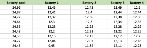
As can be seen, the voltage dropped significantly the last hour for battery 1, and went up for the battery pack as whole. Do you have any idea why this might have happened? The lights still worked fine.
I then disconnected the load, and measured the voltage again after 18 hours. It had then returned to the following:

These numbers should indicate that the system had approximately 70-80% left of the capacity, which should mean the system works somewhat fine. The battery drop on the last measurement is strange though, do you have an idea of why this might have happened or what is wrong?
-
You disconnected the load, but was the solar array still connected?
Home system 4000 watt (Evergreen) array standing, with 2 Midnite Classic Lites, Midnite E-panel, Magnum MS4024, Prosine 1800(now backup) and Exeltech 1100(former backup...lol), 660 ah 24v Forklift battery(now 10 years old). Off grid for 20 years (if I include 8 months on a bicycle).
- Assorted other systems, pieces and to many panels in the closet to not do more projects. -
Looks like there is some imbalance between the two strings, one is discharging deeper than the other, this could be due to configuration, I'm guessing the diagram in post 3 is not the actual wiring. Reading this link will answer many questions, the current during charging and dischargeing should be equal or very close in each string. This, if not corrected will lead to the premature loss of capacity of the string doing the most work.
1500W, 6× Schutten 250W Poly panels , Schneider MPPT 60 150 CC, Schneider SW 2524 inverter, 400Ah LFP 24V nominal battery with Battery Bodyguard BMS
Second system 1890W 3 × 300W No name brand poly, 3×330 Sunsolar Poly panels, Morningstar TS 60 PWM controller, no name 2000W inverter 400Ah LFP 24V nominal battery with Daly BMS, used for water pumping and day time air conditioning.
5Kw Yanmar clone single cylinder air cooled diesel generator for rare emergency charging and welding. -
In additional to checking and correcting under-load balance with a clamp ammeter, battery balance will typically be improved by connecting the mid-point of B1/B2 to the mid-point of B3/B4 (assuming B1/B2/B3/B4 labeling in your diagram). But measurement and swapping batteries around is better. Adding a HA01 balancer also helps (for series balance).
When using a voltage measurement to determine SOC, it must be done with a long rest and no-load/no-charging . Under these conditions, 12.38+12.38 and 12.45+12.46 is impossible for two parallel strings. But who knows how you are identifying B1/B2/B3/B4. Could be 12.38+12.45 and 12.38+12.46 which is quite possible.
As with balance, the best way to determine battery capacity is to measure it.
I am available for custom hardware/firmware development
-
I have had a lot of experience now with batteries
I wont blast you with numbers or what your loads are...it wont matter with what I will tell you
when you buy new batteries, most likely they have been sitting in a warehouse somewhere, since they were sitting and not being charged at all, sulphation has built up on the plates
most of the time when you get new batteries (flooded lead acid) you can look inside and the plates will be grey in color....thats sulphation.....healthy batteries have a chocolate brown color on the plates
one reason they say not to mix old and new batteries is because the new ones will have more sulphation buildup on the plates and will lower the overall amphours
my suggestion is to equalize charge the batteries every other day untill the batteries take longer to charge....when batteries take longer to charge it means there is more resistance inside of them meaning there isnt and sulphation shorting anywhere
I have 3 banks of 6volt batteries in 48 volt configuration....I used to only have 2
I thought by buying the new ones it would increase my capacity...it didnt...it actually lowered it
one day I was servicing the older 2 and left the new ones on solar charge by themselves through an equalize charge for 2 days...when I hooed the other 2 back in, I noticed I didnt have to run the generator at all through the night, the next day, I found out that is was taking longer than usual to get the up to 57 volts ...and again that night, didnt have to run the generator
so I did 2 more equalize charges on the new bank again by themselves.....and now I havent run the generator hardly at all...even on cloudy days and heavy loads
hope this helps
12 panels 6 series 2 parallel 2100 watts, 1 XW60-150 CC, 16 trojan 6V batteries 8 series 2 parallel 450 Ah, 1 XW 6848 pro, 1 5500 watt champion inverter generator( I know...I need a 12Kw ) -
Note that @t00ls advice assumes flooded batteries, but I didn't see a battery type specified.
If not flooded (i.e. sealed - gel or agm) type, they should definitely NOT be equalized, as the higher voltage overcharge could easily ruin them.
Off-grid.
Main system ~4kw panels into 2xMNClassic150 370ah 48v bank 2xOutback 3548 inverter 120v + 240v autotransformer
Night system ~1kw panels into 1xMNClassic150 700ah 12v bank morningstar 300w inverter -
4x240 Watts = 960Watt PV , with 2/3 normal operating conditions ≈ 640 Watt PV
÷ 1.3 losses ≈ 500 Watt , that reach
the batteries of 24*240 = 5760 Watts
It would take approx . 2800 ÷ 500 ≈ 6 hours to fully charge the batteries from a 50% Depth of Discharge .
Since the location is near equator , are the panels East-West oriented ,
or North ?
For the load , one should probably charge them from the grid ,
and unload them once , to have some real-to-expect values first ,
and then go the solar charging way .
-
If the diagram is actual wiring and his last 8th hour measurement is correct then all the 12 formulas of Ohms law that have been used here to figure this out might need a Quantum answer. Since "time" was used in this test, anything is possible..


Categories
- All Categories
- 230 Forum & Website
- 137 Solar Forum News and Announcements
- 1.3K Solar News, Reviews, & Product Announcements
- 181 Solar Information links & sources, event announcements
- 892 Solar Product Reviews & Opinions
- 252 Solar Skeptics, Hype, & Scams Corner
- 22.5K Solar Electric Power, Wind Power & Balance of System
- 3.5K General Solar Power Topics
- 6.7K Solar Beginners Corner
- 1K PV Installers Forum - NEC, Wiring, Installation
- 2.1K Advanced Solar Electric Technical Forum
- 5.6K Off Grid Solar & Battery Systems
- 428 Caravan, Recreational Vehicle, and Marine Power Systems
- 1.1K Grid Tie and Grid Interactive Systems
- 656 Solar Water Pumping
- 816 Wind Power Generation
- 620 Energy Use & Conservation
- 623 Discussion Forums/Café
- 316 In the Weeds--Member's Choice
- 74 Construction
- 125 New Battery Technologies
- 108 Old Battery Tech Discussions
- 3.8K Solar News - Automatic Feed
- 3.8K Solar Energy News RSS Feed