A/C Disconnect blows 1 of 2 fuses

On a net metered system with two identical arrays-16 panels 325W ea., one of the two 25amp fuses blows intermittently.
I put an amp clamp on each of the A/C outputs in the disconnect box and they both read up to 35amps. I’m a little confused at the reading vs. the fuse ratings of 25amps. The readings fluctuate anywhere from 10 to 35amps on a partly sunny, cloud moving day.


I don’t understand how the output fuse can blow going to the meter (after the home breaker panel.) Is this a utility issue? All of the connections in the disconnect box are tight including the fuse holders.
Thanks for you thoughts!
Comments
-
So you could have more than 5200W on each fuse and some would say 21.67A (which is too close to 25A). Except that contrary to popular opinion, amps don't equal watts/volts (because of power factor). Are your wires large enough to handle a larger fuse?
I am available for custom hardware/firmware development
-
Can you tell me a bit more about your system?
Roughly, the maximum your array can output is around:
- 16 * 325 Watt panels * 1/240 VAC = 21.7 amps per string @ 240 VAC
And realistically, that is only under perfect conditions with an array that is probably sub freezing temperature. Nominally, the typical maximum current you would see is:
- 16 * 325 Watt array * 0.77 solar panel + GT inverter deratings = 16.7 Amps typical max current under "good solar noon conditions"
The point you are measuring current... Is that the common output of (one or two) your GT inverter and the 2x arrays going to the utility meter?
And what is the Brand/Model number of your GT inverter(s)?
Normally, I would highly suggest that you take the max continuous output rating of the inverter (say 15 amps @ 240 VAC) and multiply by 1.25x:
- 15 amps * 1.25 NEC continuous current derating = 18.75 or ~20 Amp rated branch circuit breaker and wiring.
-Bill
Near San Francisco California: 3.5kWatt Grid Tied Solar power system+small backup genset -
My mistake. The panels were 320s not 325s.
Here is the configuration and test points.
The output from the manual disconnect (POCO code) goes to a 30A breaker in the main panel.


-
I don't know about code, but it looks to me like you could safely try 30A fuses.
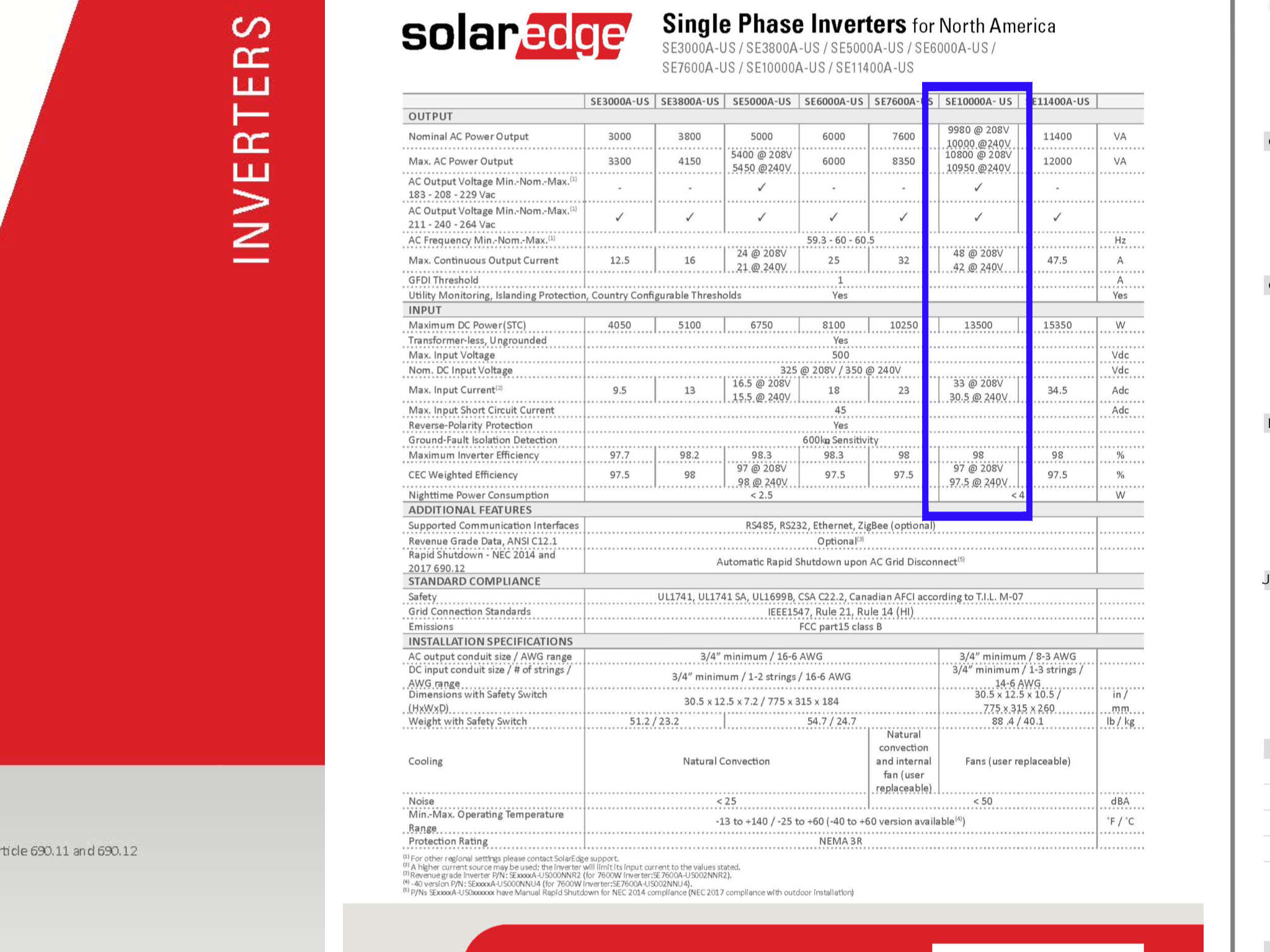
But maybe there is a bigger issue. The worksheet says max AC amps from the inverter is 12A (where 25A fuses would be fine). Yet you actually seem to have a single inverter with 42A max output - wired to 25A fuses on L1/L2? Looks like a mistake that would require bigger wire, fuses and circuit breaker.
I am available for custom hardware/firmware development
-
If you have an IR thermometer check the temperature of the fuses as well as all terminals whilst at it, if the fuses are hot they may be rated too close to the current being passed through them. 10 AWG allows 30A OCP which might solve the problem, or replace with a circuit breaker, no more fuse replacement.
1500W, 6× Schutten 250W Poly panels , Schneider MPPT 60 150 CC, Schneider SW 2524 inverter, 400Ah LFP 24V nominal battery with Battery Bodyguard BMS
Second system 1890W 3 × 300W No name brand poly, 3×330 Sunsolar Poly panels, Morningstar TS 60 PWM controller, no name 2000W inverter 400Ah LFP 24V nominal battery with Daly BMS, used for water pumping and day time air conditioning.
5Kw Yanmar clone single cylinder air cooled diesel generator for rare emergency charging and welding. -
2nd with checking with an IR thermometer - if there is a weak spring on a fuse holder, or a poor connection, it will preheat the fuse and it will blow at a lower amperage.
Powerfab top of pole PV mount | Listeroid 6/1 w/st5 gen head | XW6048 inverter/chgr | Iota 48V/15A charger | Morningstar 60A MPPT | 48V, 800A NiFe Battery (in series)| 15, Evergreen 205w "12V" PV array on pole | Midnight ePanel | Grundfos 10 SO5-9 with 3 wire Franklin Electric motor (1/2hp 240V 1ph ) on a timer for 3 hr noontime run - Runs off PV ||
|| Midnight Classic 200 | 10, Evergreen 200w in a 160VOC array ||
|| VEC1093 12V Charger | Maha C401 aa/aaa Charger | SureSine | Sunsaver MPPT 15A
solar: http://tinyurl.com/LMR-Solar
gen: http://tinyurl.com/LMR-Lister , -
Those fuses appear to have adapters, being too small for the disconnect holders, taking a voltage reading across the screw terminals of each fuse, under load , would determine if the contact is good, there should be a close to zero volt reading. Also verify if the fuses are allowed for the disconnect using the adapters, the recommended fuse is Crouse Hinds Arktite APJ 6485 OR NPJ 6485, these can be cross referenced to other manufacturers.
1500W, 6× Schutten 250W Poly panels , Schneider MPPT 60 150 CC, Schneider SW 2524 inverter, 400Ah LFP 24V nominal battery with Battery Bodyguard BMS
Second system 1890W 3 × 300W No name brand poly, 3×330 Sunsolar Poly panels, Morningstar TS 60 PWM controller, no name 2000W inverter 400Ah LFP 24V nominal battery with Daly BMS, used for water pumping and day time air conditioning.
5Kw Yanmar clone single cylinder air cooled diesel generator for rare emergency charging and welding. -
Unless I am reading your documentation wrong--There are some big mistakes in the AC output rating of the GT inverter to Main panel calculations. And possibly and issue with the "rating" of the AC mains panel and main breaker vs solar feed.
First the AC branch circuit wiring. For your array, in very cool weather (say you are in New York State), your array could be expected to produce:
- 32 panels * 320 Watts = 10,240 Watts (peak on cool/clear winter day)
- 10,240 Watts / 240 AC nominal line voltage = 42.7 Amps (rare maximum current)
And your GT Inverter is rated for 42 Amps @ 240 VAC max output current. So, that is the maximum we would use for branch circuit calculation. Add 1.25 x max continuous current (derate wiring and breaker for continuous current):
- 42 amps max * 1.25 NEC derating = 53.5 Amp rated branch circuit and fuses/breakers
10 AWG wiring is, at best, rated for 30 Amps of current (NEC has a max current rating for 14/12/10 AWG cables). The calculations seem to imply that somebody thought 12 amps max output from GT inverter? And thermal derating was 38.4 Amps (derating over 2x actual 15 amp rating?????--Should have gone down).
So, rounding up from 53.5 amps to 60 Amp breaker and wiring--Should have been wired for ~6-4 AWG wiring (depending on insulation, conduit fill, temperature deratings).
Next, you are allowed to take a 200 Amp panel (residential) and run 1.2x more current for GT solar:
- 200 Amp * 1.2 = 240 Amp maximum panel rating.
If you have a 200 Amp main breaker, then your maximum solar input could be 40 Amps--However, you are looking at needing a 60 Amp branch circuit... That means (if you do not install a new main panel) that your main breaker needs to be derated to:
- 240 Amp box rating - 60 Amp GT branch circuit breaker = 180 Maximum Main Breaker
This gives you the headroom for your 60 Amp branch circuit.
Given that you are seeing >36 Amps in the above photo:
- GT Inverter photo: 9,397.9 Watts / 256.1 VAC mains voltage = 36.7 Amps
I would expect that you are blowing a lot of 25 amp fuses... The way NEC usually works, fuses will not blow at 80% of rated current, and will eventually blow (minutes to hours) at 100% of rated current.
The fix--Check your NEC book, remove the #10 AWG wiring from GT inverter to Main panel, and install #6 or #4 copper cable (depending on insulation temperature rating and conduit fill derating), and change to 60 Amp fuses for the solar branch circuit. Also drop the main breaker to 180 Amps (or next available smaller AC mains breaker) to stay within the NEC solar design requirements for the main panel.
I may be wrong... I am not an NEC code person or an electrician/building inspector. But the above is how I would be approaching the problem.
If an installer did the work, get them out there. The building inspectors will frequency miss glaring issues--And at least in my area--Building Inspectors are not liable for any of their mistakes.
If the installer gives you any problems, educate your building inspector and get him on the installer's behind.
Remember that the GT inverter is "native" 240 VAC--And the Red/Black 240 VAC phase wires are carrying 100% of the "42" amps of rated current--They are not carrying 1/2 the current each (perhaps not understanding how Split Phase 120/240 VAC north American power works?).
-Bill
Near San Francisco California: 3.5kWatt Grid Tied Solar power system+small backup genset -
I notice that they spliced the GT Solar Inverter directly to the meter socket...
So, the code behind splicing in two drops from 1 meter--That is usually jurisdiction dependent (many do not allow for residential).
Or I am confused, the drawing show a main's side splice, but your text says goes to a 30 amp breaker in main panel... Not sure which is right...
In California, the Utility/code has dropped the requirement for a separate GT Solar disconnect (which was supposed to mounted outside the home, to allow the utility to kill your GT solar when working on their distribution system (power lines/transformers).
Originally, if you did not have an external disconnect, they would threaten to pull your meter until the linemen were done (they did not trust GT inverters to safely shutdown when mains power failed).
Today, we do not have to have a Solar AC disconnect. (DC Solar Array disconnect--A whole different kettle of fish in the newest NECs).
And if you are connected to a 30 Amp breaker in the main panel (solar GT inverter connection should be on the far side the AC bus in the panel, away from the Mains AC input breaker), then the fuses are really redundant (we used simple un-fused disconnects in our system). The AC branch circuit breaker in the Main Panel is fine (and should be 60 Amps in my estimate of your system--As there is probably no 55 Amp rated breaker).
-Bill
Near San Francisco California: 3.5kWatt Grid Tied Solar power system+small backup genset -
Seems there was an error made in the AC output maximum current, 11A was used rather than the actual maximum of 42A @ 240V, according to inverter specs. The maximum short circuit current for the optimizers is 11A, my guess is that was used by mis take
. Looking at the schematic the calculation for 125% of inverter output uses 24A as a value to arrive at 30A OCPD, which shows connected to the distribution main lug terminals. Definitely call the installer before implementation of any changes.
One other question I would ask is the connection to the main lugs, if applicable, there is provision that allows loads to be connected to main lugs provided there is a disconnect within a certain distance ~15 feet, but I'm not sure about feeding.
1500W, 6× Schutten 250W Poly panels , Schneider MPPT 60 150 CC, Schneider SW 2524 inverter, 400Ah LFP 24V nominal battery with Battery Bodyguard BMS
Second system 1890W 3 × 300W No name brand poly, 3×330 Sunsolar Poly panels, Morningstar TS 60 PWM controller, no name 2000W inverter 400Ah LFP 24V nominal battery with Daly BMS, used for water pumping and day time air conditioning.
5Kw Yanmar clone single cylinder air cooled diesel generator for rare emergency charging and welding. -
Just a quick update today. The vendor recommended 30a fuses and they were installed. There was no differential voltage across either fuse under load.
on a special note, last time in I swapped arrays at the disconnect. The problem moved with the swap. Not a good feeling...time will tell.
-
I don't understand what "I swapped the arrays" means...
Your controller has two solar panel inputs and a single 240 VAC output...
Are you saying that swapping the arrays changed the "blowing fuse" from "A" to "B" slot in the disconnect?
Running 36 amps through 25-30 amp fuses... They will typically blow in many minutes to an hour or so (fuses are quite variable in their Current/Trip curves).
Very Roughly, your 30 amp fuse is designed to trip at ~1 minute with 70 Amp steady state current:
http://www.ferrazshawmutsales.com/pdfs/TR-TRS-Advisor.pdf
http://www.ferrazshawmutsales.com/pdfs/TRTRS.pdf
Time delay fuses are not doing anything positive here... GT Inverters do not have a "starting surge" like an Induction Motor where you would need to use the Time Delay feature to avoid "popping" a fuse while starting a large motor.
You can argue with high temperature insulation, you can run 40 amps through 10 AWG cable (not sure you are allowed because of NEC limit on 10/12/14 AWG wires of 30/20/15 amp hard limit).
The system could work OK with 10 AWG cable and THHN/THWN/etc. 90C rated insulation... And you should use a 40 Amp fuse (and main panel branch circuit breaker) minimum (or with 10 AWG 90C insulation maximum).
I have have taken care of a small 1950's apartment building with electric water heaters that run something like 19.8 amps on 14 AWG wire (14 AWG is rated to carry 20 amps, but code limited to 15 amps) and a 15 Amp breaker. After many decades, I finally had a couple breakers fail--And on one unit, I had to change out the breaker and wiring to 10 AWG and 30 Amp breaker to stop nuisance trips.
The building permit chart is wrong--GT inverter is rated for 42 Amps, not 11 Amps. 10 AWG is not rated for 42 Amp load. A 40 Amp set of fuses and panel breaker would probably work (much better than 25/30 Amp fuses/breakers), and at 40 Amp branch circuit, the 200 Amp box and Main breaker is rated for that 40 amp branch circuit.
But, it is not really right. Years down the road, you could have issues (40 amp breakers/fuses fatigue when operated at maximum rated current and temperatures over time, insulation can degrade from heat).
Present installation is not to code (with 25/30 amp fuses/breakers). If you paid them for the installation (vs DIY install)--I would have them fix the installation to be right.
We have had examples of installers here that simply do not understand Solar Power systems, and they just wire everything as they always have.
Have them update/fix your wiring diagram/specifications--And if they say "40 amps is good enough". Show them the system specification that says 42 Amps maximum and you want a letter from them saying that connecting a 42 amp GT Inverter is legal (to NEC or other local building codes) and safe. They won't do that.
Talk with your Building Inspector (if you have one), and see what they say--And use him/her to push the vendor to fix.
-Bill
Near San Francisco California: 3.5kWatt Grid Tied Solar power system+small backup genset -
Swapped arrays-swapping the black (2) and red (2) wires to the opposite fuses. The reds are where the blacks were and vice versa. MPPT1 & 2 AC outputs. Originally, fuse left blew twice. Now fuse right blew after the swap. When you say single 240v output, that is 120 on each fuse, with an output to a 2 pole 30@ breaker in the main panel. The load on fuse left is now sourced on the right fuse. The problem moved with the swap.
-
For a 240 VAC GT inverter, the entire current flow is thru L1 and L2 (black and red). There is virtually no current flow through the white/neutral wire.
Why the two fuses that are (should be) carrying near identical current choose to blow following the Red and Black wire swaps... I do not know. But per your photo of the inverter's output (Power/Volts=Amps), there is around 36.x amps flowing in the Red/Black output wires/fuses/breakers at that moment in time.
Could be fuses differ by lot number, variable mfg. tolerances (and still be within spec), different fuse clamping forces, or some current is being shared with the White wire--Don't know.
You can use your AC clamp meter to measure L1/L2/Neutral currents in the middle of the day (when sun is up). Ideally, L1=L2 current, and Neutral is near zero.
You can put both L1 and L2 in the current clamp, and the sum of their current should be zero amps.
I guess it is possible that the 240 VAC mains are not symmetrical around neutral (say one Leg reads 110 Volts to neutral, and the other reads reads 130 volts to neutral. I guess you could get some non trivial current flow in the neutral conductor and the L1 current will not equal L2 current flow (presumably, the "110 VAC" leg could be passing more current than the other hot leg). And the "blowing fuse" would follow the low voltage leg (pure SWAG on my part).
Still does not "fix" a 42 Amp current source on a 30 Amp rated branch circuit.
NEC requires an 80% derating on continuous current circuits (hours of current--Such as lighting circuit in Gym). A 40 Amp branch circuit should only be "loaded" (or sourced in this case):
- 40 amps * 0.80 NEC derating = 32 Amps maximum continuous current.
Will a 40 Amp circuit carry 36-42 amps for a few hours a day (mid day, full sun)--Probably you would never know the installation "error" in your lifetime.
"My nemesis" 19.8 amps on a 14 AWG circuit for an electric water heater did not cause much in the way of problems from ~1955 to 20015 before I had to redo the wiring and breaker.
-Bill
Near San Francisco California: 3.5kWatt Grid Tied Solar power system+small backup genset -
Bill, really appreciate your knowledge and suggestions. A great help. This saga isn’t over, more details to follow as time progresses. For me, a DIYer, this is a great site for learning. I appreciate everyone’s feedback.
-
Well, the design people fessed up. A mistake was made and, they offered the same solution Bill posted, albeit they didn’t mention anything about downsizing the mains breaker. As far as I can tell, the next step down is a 175@ breaker. I’m not sure I understand the formula for this replacement. In any case, thank you all, especially Bill, for a job well done!
-
Bill,
Under ABYC code (American Boat and Yacht Code) standard marine code set 14 AWG wire is rated 45 amps!
NEC code set is very conservative!
David
2 Classic 150, 2 Kid, 5 arrays 7.5 kw total 2ea. 2S6P Sharp NE-170/NE-165, 1ea. 12P Sanyo HIT 200, 2ea. 4/6P Sanyo HIT 200, MagnaSine MS4024AE, Exeltech XP-1100, 2 Banks L-16 battery, Rolls-Surette S-530 and Interstate Traction, Shunts with whizbangJr and Bogart Tri-Metric, iCharger i208B dc-dc buck/boost converter with BMS for small form lithium 8S 16650 or LiFePO4, -
JGotts,
The derating of the main panel breaker is to meet NEC code is due to the 200 amp main breaker and the 50 amp solar main disconnect would be more than the maximum allowed 240 amps allowed on that main panel (200+50=250 amps) Downsizing the main breaker to 180 amps meets the code (180+50= 230 amps maximum) . Some brands next size down is 175 amps.
The designers of your systems sure did not do the math on this one! Yes 6 gauge wire and 50 amp breakers on the main inverter disconnect would be the proper sizing to meet the NEC and maintain your insurance! Often not noted.....if you do have a disaster and your system is not fully NEC code compliant your insurance company can wiggle out of payment due to this. Qualified second opinions can be very beneficial.
david
2 Classic 150, 2 Kid, 5 arrays 7.5 kw total 2ea. 2S6P Sharp NE-170/NE-165, 1ea. 12P Sanyo HIT 200, 2ea. 4/6P Sanyo HIT 200, MagnaSine MS4024AE, Exeltech XP-1100, 2 Banks L-16 battery, Rolls-Surette S-530 and Interstate Traction, Shunts with whizbangJr and Bogart Tri-Metric, iCharger i208B dc-dc buck/boost converter with BMS for small form lithium 8S 16650 or LiFePO4, -
David,
I prefer to think that the marine code is wildly "optimistic". 😛
JG,
I am glad they are taking ownership of a pretty basic design error on their part.
Even if you are "just the customer" and not doing the work--Many times just becoming educated enough to follow what the pros are doing--You can catch some issues, and learn to better debug your own system(s) in the future.
Regarding the Main Panel rating... As I understand (I was not involved in the writing of the NEC or the design of the panels)-Basically, the panel is designed to pass 200 Amps safely and reliably (without overheating).
When you install an GT solar inverter--You are adding another current source to the box. Technically, you have a 200 amp rated box+busbar, and a 200 amp breaker at the top (utility mains) and another energy source of 50-60 Amps at the bottom of the box... And in the middle, you technically could draw 200 Amps (main) + 60 Amps from the GT inverter--Or have 260 Amps of energy in a box rated for 200 amps.
What the NEC did, was allow you to give a +20% rating "boost" to the box--Call it 1.2*200a= 240 Amps of current source in the box.
But since 200+60 amps is >240 amps for the solar "uprating", you have to drop the main breaker by (at least) 20 amps (to 180 or 175 Amps, depending on panel and breaker mfg's product line) so that the total current sources in the box do not exceed 240 Amps.
Things can get a little bit more complex... Some boxes and internal AC bus bars are rated to 250 Amps (or so)--But the box comes with a 200 Amp breaker. Just one of those marketing decisions.
Lastly, your GT inverter breaker(s) are to be installed at the opposite end of the bus bars from the Mains Breaker. This so that no point on the bus bar sees more that 200 Amps (if you put the 180 amp main breaker and 60 amp solar breaker next to each other, then the bus bar could see 240 amps total).
Why did they choose x1.2 for uprating the box? I have no idea other than they believed the boxes were safe to be up rated by that amount (remember 1.2*1.2 = 1.44x more waste heat in the box == Power=I^2 * R).
I squared R heating is a major design concern... 2x more current in a wire (or box) is 4x more waste heat.
-Bill
Near San Francisco California: 3.5kWatt Grid Tied Solar power system+small backup genset -
JG,
I should add that I still have two questions:
First, where does the GT inverter 240 VAC output land in the main panel? Is it to a double pole (50 or 60 amp) breaker at the "bottom" of the main panel--Or is it spliced in the Meter feed to the Main Panel breaker? (I would be highly suspicious that a meter splice is legal)
Also, if the GT solar goes to a 2 pole breaker in the mains panel (where I think it should connect), then you really do not need a fused GT disconnect (fuses only needed if meter side splice is made).
Second, It appears that the GT solar disconnect is inside a basement or garage. According to the wiring diagram, the GT Solar disconnect is supposed to be outside (generally accessible to the Lineman so they can turn off your GT Solar if they are working on the electrical lines in your area). If you do not have an exterior GT solar disconnect, the linemen may pull your meter (and kill power to the whole house) until they are done working in your area and replace the meter back into its socket.
Many years ago, California agreed that GT Solar Inverters will quickly and safely shutdown if there is a utility power interruption (car takes down pole, trees take out wires). And we no longer have to have a specific GT Solar AC disconnect.
In any case, it seems that the location of the solar disconnect does not meet their permit application ("located outside").
-Bill
Near San Francisco California: 3.5kWatt Grid Tied Solar power system+small backup genset -
Bill,
Square D does market 240 amp versions of the 200 amp main box, mostly for commercial or other uses. You will not find these at Home Cheepo but you will find them in the full line catalogues available at the stocking distributors. So the busses and backplanes are rated 240 amps on Square D Home Line and QO commercial boxes, same for Seimens. I generally do not use the othe r brands except maybe Cutler Hammer CH Line, not the BR line. I'm picky about my quality. I through out many failed boxes that did not last 10 years. I am not about to use those in an upgrade. Don't even ask me to repair a Stab-lok
i agree about the ABYC being overly optimistic but the NEC is conservative for a very good reason.....Safety!
david
2 Classic 150, 2 Kid, 5 arrays 7.5 kw total 2ea. 2S6P Sharp NE-170/NE-165, 1ea. 12P Sanyo HIT 200, 2ea. 4/6P Sanyo HIT 200, MagnaSine MS4024AE, Exeltech XP-1100, 2 Banks L-16 battery, Rolls-Surette S-530 and Interstate Traction, Shunts with whizbangJr and Bogart Tri-Metric, iCharger i208B dc-dc buck/boost converter with BMS for small form lithium 8S 16650 or LiFePO4, -
> ABYC code (American Boat and Yacht Code) standard marine code set 14 AWG wire is rated 45 amps!
But only single wires with 200C insulation. In an engine space with low temp insulation, 14 AWG is ABYC rated for as little as 6A. Far less than NEC!
Marine code is more accurate and safer, not optimistic.
I am available for custom hardware/firmware development
-
Currently, the feed is at the lowest point in the panel on a 30@ breaker. Yes, this is indoor and the diagram shows outdoor, that will need to be addressed on the revision to the plans. If the new 60@ breaker is installed, I will question the elecrician regarding the manual disconnect removal. I was under the impression it’s installation was driven by the POCO requirements. I suppose because of the vendors “SafeDc” shutdown system (which would only allow 16v production from each string to the inverter in the event of utility power loss) the issue of disconnect is moot. Additionally, if the manual disconnect were eliminated, the utility would be at the mercy of an indoor mains panel breaker anyhow.
Thanks for the details on the calculations. I’m feeling more comfortable about the configuration and it’s operation!
-
You are correct, the outside disconnect was a "strongly suggested" requirement. Allow the linemen to disconnect without pulling your meter.
Something like 10-15 years ago or so, the UL anti-islanding function of the GT inverter was "good enough", the the requirement was dropped by California utilities.
There is a whole bunch of new safety requirements around the installation of solar panels for fire personal. Remote array shutdown and roof access for ventilation (setbacks/paths). I don't really know much about those current requirements (cities have to accept the next revision of NEC--And some are a few revisions "out of date").
-Bill
Near San Francisco California: 3.5kWatt Grid Tied Solar power system+small backup genset -
Oh, BTW, turns out that the electrician was supposed to do a line side tap. So now the remedy is put in 60@ fuses & disconnect the 30 MP breaker and change over to 6ga. wire. I got so hung up at the 25@ fuse issue the connection to the main was missed. Don’t know howit wound up going to the 30@ MP breaker to begin with. Refer to 1st image.
-
JG,
I am making some comments here about the meter side tap... I am not an NEC code person by any stretch... I am a systems design engineer who occasionally had to work with code (and code engineers).
I do not like line side taps unless you have to do one, follow code, and is "legal" with your building department (not commonly allowed for residential installations).
Second, just looking at the issue from a system design point of view.
- Pole transformers are rated at 10,000 Amps maximum output (internal magnetics designed to saturate >10k Amps). And you probably have 2 AWG or heavier (aluminum typically). Note that your circuit breakers (mains and branch circuit) are rated for 10,000 Amp AIC (i.e., rated to break a dead short to a pole mounted transformer--more or less, there are some details that don't usually apply to home installations).
- The first "fuse/overcurrent protection is in the solar disconnect). And you are planning on running 6 AWG copper wire from disconnect to meter side splice. Typically 6 AWG copper wiring "fuses" around 600 Amps. For a Mains/Meter side tap, I do not know what the minimum cable AWG is (aluminium is typically 4 AWG "heavier" than similarly rated copper). I would double check code to see if 6 AWG copper is even allowed on a meter side tap.
- If you install a 180 amp (or 175 for your brand of panel) main disconnect, your panel would then allow a 60 (or 65) amp GT Solar feed (which is plenty for your solar power system).
- Drawback is now your main breaker would be 175 Amps maximum and would limit your home to 175 Amps maximum (if the sun is not shining)... You would have to look at code and your rules and your installed appliances (all natural gas cooking/heating/hot water, no AC--Or all electric home with big AC system)?
- If you do the 175 Amp main and 60 Amp branch circuit GT solar breaker, your 6 AWG wire is properly protected by the 60 Amp breaker (branch circuit breaker in main panel) its whole length.
- If your electrician installed the GT solar disconnect outside--That is a long run for an unfused supply (if meter side tap). You may also need something heavier than thin wall conduit for mains cabling).
As I said, I am not a code guy--Others here (and your electrician/system designer(s)) should be able to better able to address this supply side tap issue and safety.
For you, the decision (beside the safety issue) is whether or not a 175 Amp service is "enough" for your home.
And if you were expecting a 200 Amp service and the solar guys derated to 175 amp (following standard NEC code), would they (or you) pay for a 240 Amp main panel?
- 240a*1.2 NEC solar uprate=288 amps total
- 288a-60a GT circuit=228 amp available (assuming a 220 Amp mains breaker is available, or simply go with 200 Amp mains breaker and 60 amp GT branch circuit).
Sorry that I have more questions/confusion than answers. 😕
-Bill
Near San Francisco California: 3.5kWatt Grid Tied Solar power system+small backup genset -
BB,
The main breakers in all boxes for use in NEC residential installations are rated 10kAIC. The branch breakers do not need the 10kAIC rating, and are not supplied in standard boxes. In commercial installations where the utility transformer is very close to the service drop the AIC rating of the main breakers Is increased to 30kAIC and the branch breakers cannot be in the main panel but must be in a sub panel more than 70 feet by wire run from the main panel. I have seen commercial buildings where 50 horsepower of machinery is used with a "inspector requirement" of 50 kAIC main breakers to adequately protect the installation. These installations typically are 480 volt wye 3 phase with a 75-125 kW utility transformers.
for those who do not understand the AIC requirement....in a nutshell.....there is an overload point where the breaker will fuse .....weld the contacts in the on position. This is very dangerous! The AIC " Amps interrupt capability" is there to protect from this situation. The 200 amp 10 kAIC breaker will open at 240-250 amps under load but will withstand a dead short circuit of 10,000 amps and will not weld....it will reliablely open. A breaker with a lesser AIC rating could fuse and leave the circuit not protected. A "burn down possibility" to be avoided. There are many requirements in the code that are not well understood and this is one of them.
A branch breaker box cannot be used as a main box for this very reason...branch breakers are not rated 10k AIC
THe NEC is so complicated that licensed electricians often have a book called "Understanding the NEC" I certainly have it!
2 Classic 150, 2 Kid, 5 arrays 7.5 kw total 2ea. 2S6P Sharp NE-170/NE-165, 1ea. 12P Sanyo HIT 200, 2ea. 4/6P Sanyo HIT 200, MagnaSine MS4024AE, Exeltech XP-1100, 2 Banks L-16 battery, Rolls-Surette S-530 and Interstate Traction, Shunts with whizbangJr and Bogart Tri-Metric, iCharger i208B dc-dc buck/boost converter with BMS for small form lithium 8S 16650 or LiFePO4, -
Dave,
I will not argue the NEC and branch breaker AIC ratings... It has been many decades since I cracked open the NEC, and this was not my area of need (internal wiring for computer systems).
The 10kAIC was what I was used to seeing on branch circuit breakers
ANSI-certified and UL-listed unit is rated for 120 VAC and 10,000 AIR. Homeline circuit breakers are built with the same Square D brand quality...
I cannot even figure out if "AIR" is the same as "AIC" or not (or simply a typo/autocorrect on a web page)...
-Bill
Near San Francisco California: 3.5kWatt Grid Tied Solar power system+small backup genset -
Bill,
I just looked at my Square D catalog......there is no mention of AIC anywhere.....everything is rated AIR! Breakers, boxes , everything. Had never noticed that. Most of my expereince is industrial. That is where the high quality work is. QO line boxes and main breakers are rated 22,0000 AIR minimum some are 42,000AIR. and 65,000AIR The branch breakers are all 10,000AIR. Homeline boxes and breakers are rated 10,000AIR
So it's wording...amps interrupt capability....amps interrupt rating.......UL does "rate" stuff, just because it does have that capability does not mean that UL or any other NRTL "rated" it at that. As far as the code "it is what a NRTL rated it at" Nice little bit of legalese. I do not do new residential installations, very few repairs. I upgrade services but my mainstay is agriculture and industrial. Most of my work is 3 phase. I tinker in solar and do not do grid tie, I will remove it and restore service to utility. Off grid is frowned upon here and I do not wish to deal with inspectors so I prefer to help people with their systems. Both standard utility service and off grid.
My apologies for the confusion on the wording .
david
And to deepen the plot, just peeked at my CBI breaker data sheet.....10kA interrupt capability....no mention of AIR.........so are the terms interchangeable? Legalese? Now I'm totally confused on the issue I always thought the correct term was AIC.....Amps interrupt capability.
2 Classic 150, 2 Kid, 5 arrays 7.5 kw total 2ea. 2S6P Sharp NE-170/NE-165, 1ea. 12P Sanyo HIT 200, 2ea. 4/6P Sanyo HIT 200, MagnaSine MS4024AE, Exeltech XP-1100, 2 Banks L-16 battery, Rolls-Surette S-530 and Interstate Traction, Shunts with whizbangJr and Bogart Tri-Metric, iCharger i208B dc-dc buck/boost converter with BMS for small form lithium 8S 16650 or LiFePO4, -
No problem David,
English and technical vocabulary was (is) my weakness. AIC was what I was always used to seeing too.
I have done some UL/NRTL registered equipment over the years... They are not magic, but do add some sanity to, what can be, a very complex supply chain quality nightmare (their inspections of factories, certification tags from suppliers, final assembly test, checking calibrations of equipment and such).
What they (the NRTLs) did for Solar Panels (actual environmental and functional testing) was not common to office computer systems. In decades past, many countries used the system prior to NRTLs (nationally recognized testing laboratories) as non-tariff trade barriers (if you did not "test" with a "local" laboratory, your stuff sat on the docks).
-Bill
Near San Francisco California: 3.5kWatt Grid Tied Solar power system+small backup genset


Categories
- All Categories
- 231 Forum & Website
- 138 Solar Forum News and Announcements
- 1.3K Solar News, Reviews, & Product Announcements
- 181 Solar Information links & sources, event announcements
- 893 Solar Product Reviews & Opinions
- 252 Solar Skeptics, Hype, & Scams Corner
- 22.5K Solar Electric Power, Wind Power & Balance of System
- 3.5K General Solar Power Topics
- 6.7K Solar Beginners Corner
- 1K PV Installers Forum - NEC, Wiring, Installation
- 2.1K Advanced Solar Electric Technical Forum
- 5.6K Off Grid Solar & Battery Systems
- 428 Caravan, Recreational Vehicle, and Marine Power Systems
- 1.1K Grid Tie and Grid Interactive Systems
- 656 Solar Water Pumping
- 816 Wind Power Generation
- 620 Energy Use & Conservation
- 623 Discussion Forums/Café
- 316 In the Weeds--Member's Choice
- 74 Construction
- 125 New Battery Technologies
- 108 Old Battery Tech Discussions
- 3.8K Solar News - Automatic Feed
- 3.8K Solar Energy News RSS Feed