Sanyo mini split AC (inverter/variable speed)
Comments
-
Re: Sanyo mini split AC (inverter/variable speed)
Hello all.
I finally elected to install a 12,000 (23 seer) and 18,000 (20.5 seer) mitsubishi hyber heat system. The units were finally operational as of yesterday and are working well; very pleased.
However, i am concerned that the contractor seems to of not of done a pressure test and possibly some other test?. he performed a vaccum test... but not pressure. I learned this from one of the employees who was doing the test... he said something about the mitsubishi did not have the right ports for his equipment... but assured me everything was fine (though his comments raised concern to me). I had read somewhere else about problems with not having the right port adaptors for some of the mini splits... my concern is if he lacks proper port adaptors; is maybe something else might not of been tested or monitored correctly in addition to pressure test?... one thing for sure it seems the pressure test was not done.
Anyway, im not well versed in ac systems or testing; anyone know what might be going on here. I know this is not an hvac forum; however, i know some of you have had some experience installing or witness installs of minisplits.... i also have been amazed at some of the expertise that comes from this forum; so thought i might pose this question here.
thanks,
derick -
Re: Sanyo mini split AC (inverter/variable speed)
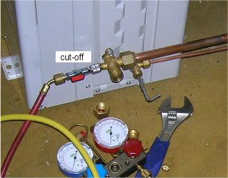
The pressure test is to insure there is no leaks in the line-set and it's four connecting flare fittings.
Basically it's looking for pin-holes in both the copper lines, a bad flare or loose flare nut.
One problem with preforming the pressure test, is that a very slow leak might not be detected with a pressure gauge.
If the air temperature changes during the test, the pressure reading will change also.
A good pressure test takes a LONG time to perform. (Think: very slow leak in a car tire).
A good vacuum test is actually the best way to insure a tight system. If you can pull <200 microns of vacuum,
it's very unlikely there is going to be any leakage when the R410A is released into the lineset.
Once a vacuum has been pulled and is holding well, the R410A can be released, while simultaneously
shutting off the pump connection (and turning the pump off).
Once the R410A floods the lineset, a simple soap bubble test can be performed on the flares.
See any bubbles, add some torque to the flare nut and re-soap.
I like to leave flare nuts uncovered for a few days, so I can add one more little torque to them,
before covering them with insulating tape. But, that's just me.")
Anyways, your installer saved some time during the install process, since there is very
little chance that he will have to come back because of a leak in the line set.
R410A runs at some pretty high pressures in the system. If you run it in heat and cool modes, you are giving it pressure tests.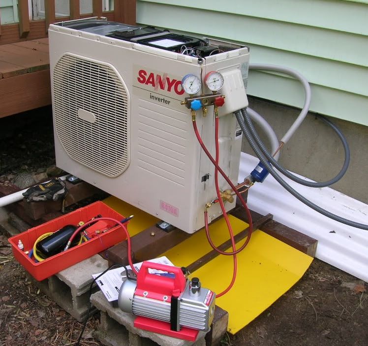
My last pressure test was only at 300 PSI, since I feared that I might have a leaky service valve.
I didn't want to force nitrogen into the system.
Edit:
The pressure test in my install manual is for the lineset and indoor unit. It uses dry nitrogen.
There is another type of common pressure test that is used to check system performance of central air systems.
It requires the gauge set manifold to be connected to both the low and high pressure sides of the lineset.
Mini-splits that I've seen do not have both those connections. They only have one service port.
So, the standard test that many service guys are used to preforming can't be done on a mini-split, due to the missing service port. -
Re: Sanyo mini split AC (inverter/variable speed)
XRinger, I totally agree with you're post, and was quite shocked at the 1/10 *ss job (considerably less than half-*ssed) that the "professional" refrigeration guy did on my mini-split installation. I did everything myself, except for the vacuum and pressure test. The vac pump he only let run for 3 or 4 minutes, then after releasing the R-410a, he checked the pressure, loaded up his van (about 5 minutes), rechecked the pressure and left. Not sure if he was making some big assumptions, or was he eyeing future profits.
Why did I get him? I didn't have a vac pump, and warranty required a professional to release the gas
-
Re: Sanyo mini split AC (inverter/variable speed)
Yeah, you need to have that HVAC for your warranty. Sadly, there are some HVAC guys who don't know much about mini-splits,
and have not sat down and read a few install manuals.
Maybe he had one of those fast pumps. 8 HP or something?
Running my little vacuum pump for 3 or 4 minutes would be okay for clearing the test hose and micron gauge connections,
but a 20 to 30 foot lineset will need at least 20 minutes to get down under 200 microns. (if it's cold out, longer run time is needed).
Once it's down under 200, you pause and let the pump cool a bit.
If there is any moisture in the lineset (& indoor unit coil), it will out-gas.
That will cause the micron meter reading to go up..
But, when you repeat the cycle a few times, it goes up less and less. (Removing about all the moisture).
IMHO, If your HVAC guy is using one of these to measure vacuum,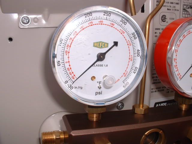
Does that say 29.89 or 29.916 ??? It makes a BIG difference (see chart below).
And doesn't own one of these,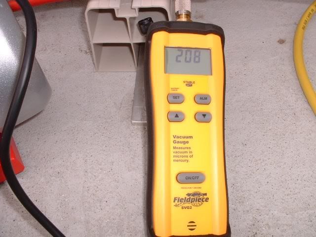
It's very likely that he's not serious about doing a good job..
-
Re: Sanyo mini split AC (inverter/variable speed)
The proper procedure for Mini split startup is the following:
Pressure test to 600 PSI N2, soap all connections.
Triple evacuate to 500 microns breaking the vacuum in between evacuations with N2
On the final evacuation pull 500 microns and shut manifold valves, and it must hold for 15 minutes, if not you have a leak or moisture still in the system.
Add additional refrigerant if required ( check line set length and add amount required for the additional distance) to the line set.
Open valves and release refrigerant.
Check to make sure unit ramps up and down in Heating & cooling mode and turns off properly.
Check running pressures and amp draw during ramp up & down.
If your contractor is not installation certified by a mini split manufacturer and does not have N2, micron gauge, or hose adapters call someone else. -
Re: Sanyo mini split AC (inverter/variable speed)The pressure test is to insure there is no leaks in the line-set and it's four connecting flare fittings.
Basically it's looking for pin-holes in both the copper lines, a bad flare or loose flare nut.
One problem with preforming the pressure test, is that a very slow leak might not be detected with a pressure gauge.
If the air temperature changes during the test, the pressure reading will change also.
A good pressure test takes a LONG time to perform. (Think: very slow leak in a car tire).
A good vacuum test is actually the best way to insure a tight system. If you can pull <200 microns of vacuum,
it's very unlikely there is going to be any leakage when the R410A is released into the lineset.
Once a vacuum has been pulled and is holding well, the R410A can be released, while simultaneously
shutting off the pump connection (and turning the pump off).
Once the R410A floods the lineset, a simple soap bubble test can be performed on the flares.
See any bubbles, add some torque to the flare nut and re-soap.
I like to leave flare nuts uncovered for a few days, so I can add one more little torque to them,
before covering them with insulating tape. But, that's just me.
Anyways, your installer saved some time during the install process, since there is very
little chance that he will have to come back because of a leak in the line set.
R410A runs at some pretty high pressures in the system. If you run it in heat and cool modes, you are giving it pressure tests.
My last pressure test was only at 300 PSI, since I feared that I might have a leaky service valve.
I didn't want to force nitrogen into the system.
Edit:
The pressure test in my install manual is for the lineset and indoor unit. It uses dry nitrogen.
There is another type of common pressure test that is used to check system performance of central air systems.
It requires the gauge set manifold to be connected to both the low and high pressure sides of the lineset.
Mini-splits that I've seen do not have both those connections. They only have one service port.
So, the standard test that many service guys are used to preforming can't be done on a mini-split, due to the missing service port.
"Mini-splits that I've seen do not have both those connections. They only have one service port.
So, the standard test that many service guys are used to preforming can't be done on a mini-split, due to the missing service port."
The above was also my concern especially in regards to servicing it down the road (not that i will need service; but you never know). I had told the contractor that it did not have a service port; but you can get one from mitsubishi... he said it had all the ports it needed.
I believe the following is the optional service port you can get from mitsibush to do the same performance tests they do on central air units?(not sure on this; maybe others could let me know if this is what was needed):
http://catalog.mitsubishipro.com/viewitems/all-categories-air-conditioner-accessories/bv-series-ball-valves?forward=1
If it was what was needed, it may be something that others might want to think about down the road to install if installing a new mitisubishi mini split (or something equivalent)... not sure its necessary; but could see where it might save a world of trouble if someone was trying to test/troubleshoot the system down the road (or even during the install if problems came up).
Thanks for all the replies.
PS.. i also have a watt load meter coming in for a generator hookup; however, i plan to hook that up to one of the mitsibushis i have over the winter. Ill let you guys know what the overall watt draw is once i get that installed.... its a mechanical watt load meter that shows total watts drawn on each leg of 240 volt circuit (its not going to be able to show wattage spikes...only the total watts it uses). Ill give more information on it once i get it installed. -
Re: Sanyo mini split AC (inverter/variable speed)
All of the mini-split units I've seen have a service port where the line set connects.
If you want to test both low and high pressure side, you do need two ports.. (Like on an old Cool only central air system)
BUT, if your mini-split does both heating and cooling, you can use the remote
to change modes (from cooling to heating) and measure both pressures..
So, maybe that's why the designers removed the extra connection from current units.?. It's not needed.
The pressures and temperature charts in the service manual are not easy to use, since the inverter type
mini-split does not run at a fixed rate for very long. The controller is constantly changing the power use, mostly downwards..
If you did want to add some junk to your low side (small) copper line set (1/4" ?) it would be very easy to do.
Just find the Pump-Down info in your manual. It only takes a few minutes to suck all the R410A back into the system.
Once the service port pressure goes negative, you close off the lineset. Then you can add your stuff,
vac out the line set again, then release the R410A again.. Simple job. But your HVAC guy will want $500 to $1,500??
(He has kids that want to attend MIT).")
-
Re: Sanyo mini split AC (inverter/variable speed)
Many "high side" ports are NOW read with electric service tools .
I have OEM tools that read the pressures from the missing ports , Low side for charging /evacuation etc, but a huge area of specialized internal electronics .
MIT , naw
Just saying & XRinger, I agree with you're post info , plus Luckman..
VT -
Re: Sanyo mini split AC (inverter/variable speed)
The high side port is under the cover near the compressor on the mini splits. Everything on the outside of the unit is lowside, so no need for an additional service port there. -
Re: Sanyo mini split AC (inverter/variable speed)The high side port is under the cover near the compressor on the mini splits. Everything on the outside of the unit is lowside, so no need for an additional service port there.
I've never noticed another service port inside my Sanyo units. If it's there, it's not easily visible.
And, the area down there by the lineset connections is pretty tight.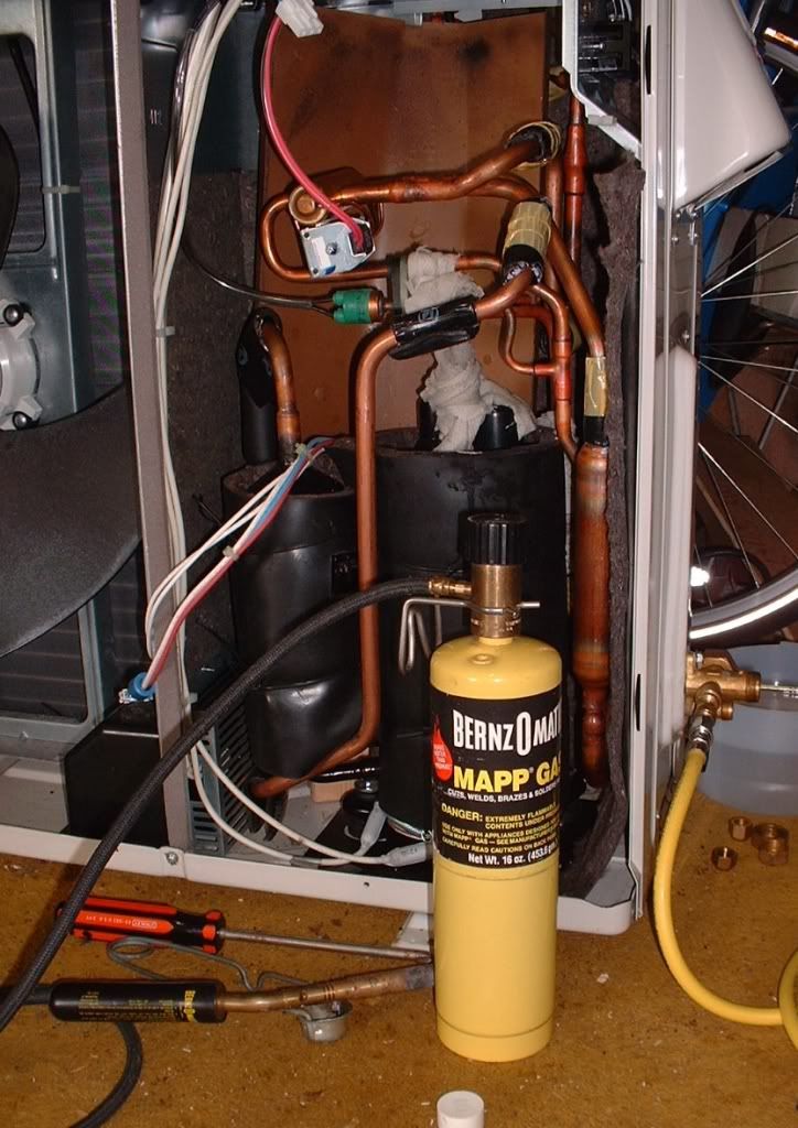
Here's a pic from my repair project. Pin-hole right above the compressor..
Wide shot..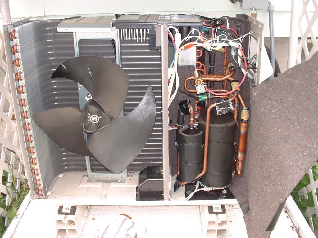
A second service port is not found in any of my manuals either.. -
Re: Sanyo mini split AC (inverter/variable speed)I've never noticed another service port inside my Sanyo units. If it's there, it's not easily visible.
And, the area down there by the lineset connections is pretty tight.
Here's a pic from my repair project. Pin-hole right above the compressor..
Wide shot..
A second service port is not found in any of my manuals either..
Looks like the Sanyo has no high side access port visible, unless that it hiding behind the reversing valve solenoid. The Mitsubishi & Fujitsu do have them installed on the discharge line just before the reversing valve. -
Re: Sanyo mini split AC (inverter/variable speed)
I've been all over that area.. The leak is marked with ">>>". Never saw a port near the change-over valve.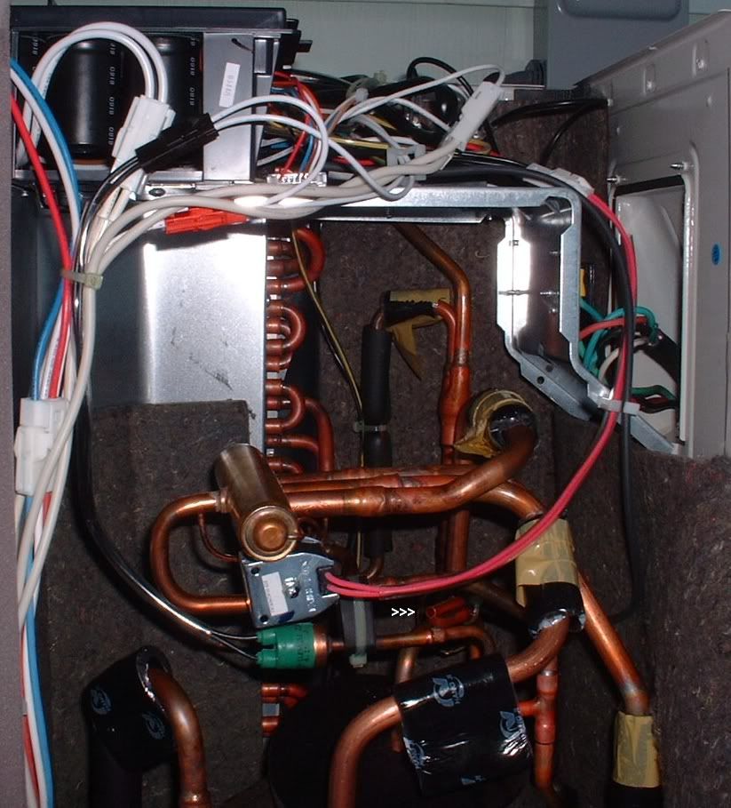
Here's the link to my repair posts.
http://ecorenovator.org/forum/geothermal-heat-pumps/1753-sanyo-24khs72-mini-split-diy-repair-project.html
The next time I do the maintenance stuff, I'll take another look, but I'm pretty sure that port doesn't exist on these old Sanyos.
Like I said before, if you want to measure both high and low pressure, you simply change modes.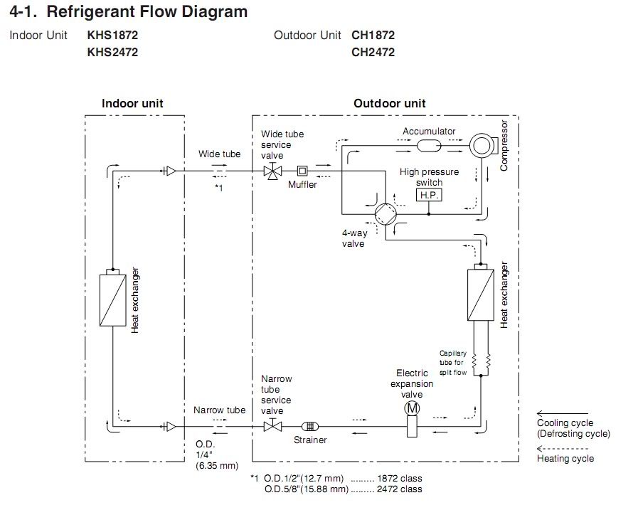
-
Re: Sanyo mini split AC (inverter/variable speed)Like I said before, if you want to measure both high and low pressure, you simply change modes.
Making the probably justified assumption that the high and low pressures will not in some weird way be dependent on system loading....SMA SB 3000, old BP panels. -
Re: Sanyo mini split AC (inverter/variable speed)Making the probably justified assumption that the high and low pressures will not in some weird way be dependent on system loading....
The pressures are very dependent on loading and the controller. I think it has some kind of fuzzy logic that sets the RPMs all over the place.. (Which changes pressures).
I did find a no-name-brand manual online that said: "If you have the two port version, there will only be about 5 PSI difference between them".. So, any two port measurements are pretty worthless..
I could get a benchmark of performance with my systems, but using the test-run mode (TRun). It's a jumper that will run the system at a fixed power level.
It varies very little once it's running. Here's a video: http://s46.photobucket.com/albums/f147/Xringer/NCL/?action=view¤t=r410a.mp4\
On this Sanyo, you can change the cool/heat mode by pulling the DC control plug off the 4-way valve's coil.
That dual port testing the HVAC guys like to do, tells them if there is something wrong with the system, like if it's low on refrigerant..
I've been told by a top-dog Sanyo engineer that, to measure for loss of R410A, you have to recover it, and weigh it! (Then replace it with new R410A).
That seems crazy, but I've read that method is pretty common in the AC biz.. -
Re: Sanyo mini split AC (inverter/variable speed)
Changing modes doesn't tell you if there is a restriction in the refrigerant lines in the outdoor unit, or if the EXV is supplied with high pressure liquid ( among many other things) it sends hot gas to the indoor unit bypassing many other components. It not going to help if trouble shooting a refrigeration problem in the cooling mode.
An experienced tech has other methods of checking if the unit is low on refrigerant other than suction pressure, and can add refrigerant with out reclaiming the system. The inverter units are more difficult than the old single speed units but it can be done. That's what the test mode is for, it bypasses the temp controller & ramps the compressor to max rpm for 15 minutes for system evalutation -
Re: Sanyo mini split AC (inverter/variable speed)That's what the test mode is for.
And In that Mode , Some who call it a "High Pressure Switch" is really a pressure transducer that gives a value .
Like I posted. = Link
At least Thats how I get to see it. Fancy tools that can get into deep diagnostic mode.
Many times the nomenclature is not always what the "switch is". Im just sayin , just because you see two wires , it has got three potentials .
VT -
Re: Sanyo mini split AC (inverter/variable speed)
I installed a 18000 btu mitsubishi fe hype heat system. I am concerned with the current draw as it is drawing for long periods of time (longer than 30 minutes) over 3700 watts (i have it in cooling mode only). The electrical specs for the unit can be found here:
http://usa.mylinkdrive.com/uploads/documents/2974/document/MUZ-FE09-18NA_Service_OBH543C_4-11_%282-6,_11-17%29.pdf
Im not sure whats up with the large current draw as the max watt draw should be around 2200 watts in cooling only mode... and that wattage i assume is if it is powerful mode (a mode which will operate for only up to 15 minutes and where it will put out much more than 18000 btu to cool the room down quicker). When it is drawing the 3700 plus watts i do not have it in powerful mode.... and even if i did the total draw still should be less than 3700 watts.
In normal cooling mode it should be drawing 1270 watts when outputing 18000 btu, yet its drawing 3 times this amount. I can understand a large spike in wattage when initially starting the unit; however, maintain a large wattage draw for more than a few seconds and instead lasting minutes or hours . The ac guy is coming out to check the system out. Wonder if you guys know anything which might be causing this excessive watt draw... could low r410 or high r410 be the cause, maybe something in the wiring or setup... dont know; but any suggestions would be welcome.
thanks,
derick -
Re: Sanyo mini split AC (inverter/variable speed)
The "High Pressure Switch" on my Sanyos controls the 230vac using the contractor relay. It's only got two functions, Closed = low pressure, open = high pressure.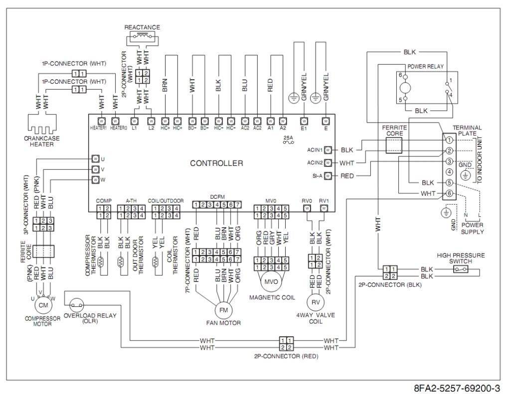
Of course, this model has been around for a few years now.. -
Re: Sanyo mini split AC (inverter/variable speed)dsharp9000 wrote: »I installed a 18000 btu mitsubishi fe hype heat system. I am concerned with the current draw as it is drawing for long periods of time (longer than 30 minutes) over 3700 watts (i have it in cooling mode only). The electrical specs for the unit can be found here:
http://usa.mylinkdrive.com/uploads/documents/2974/document/MUZ-FE09-18NA_Service_OBH543C_4-11_%282-6,_11-17%29.pdf
Im not sure whats up with the large current draw as the max watt draw should be around 2200 watts in cooling only mode... and that wattage i assume is if it is powerful mode (a mode which will operate for only up to 15 minutes and where it will put out much more than 18000 btu to cool the room down quicker). When it is drawing the 3700 plus watts i do not have it in powerful mode.... and even if i did the total draw still should be less than 3700 watts.
In normal cooling mode it should be drawing 1270 watts when outputing 18000 btu, yet its drawing 3 times this amount. I can understand a large spike in wattage when initially starting the unit; however, maintain a large wattage draw for more than a few seconds and instead lasting minutes or hours . The ac guy is coming out to check the system out. Wonder if you guys know anything which might be causing this excessive watt draw... could low r410 or high r410 be the cause, maybe something in the wiring or setup... dont know; but any suggestions would be welcome.
thanks,
derick
Yeah, something is amiss. Cooling wattage should stay between 0.57 & 2.3 kW... 1,270 (570~2,280)
The biggest problem with my old Sanyo 24k inverter units is the stupid high power ramp-up they put in the controller firmware.
I have no idea why they did it, but a 24k Sanyo will try to run up to 3.5 kW, if you try to change the room temperature more than 1 or 2 degrees.
Plus, you NEVER press the High Power button! It will ramp right up and pop the high-pressure switch or over-load relay..
So, when we come home to a hot house, I turn on the Sanyos and move the setpoint to 1 degree cooler than room temperature..
Within a few minutes, the house starts to cool and I can move the setting down another degree.. After a while, I get it down to 25 or 24 deg C and leave it..
So, one degree changes is something you might try..?.
I think the marketing guys put that giant power surge in there for the US market.. They call it 'Instant Cool'.. I call it Instant stupidity.
~~~~
After I learned to limit my temp changes to 1 deg, all was good.. But then in the winter, the defrost cycle problem popped up!
After a defrost run (cooling mode without indoor fan on), when it goes back to heating, we would randomly get a big power surge!
I think it was during one of those surges, that a pin-hole blew all the R410A out of my first system! :grr
I decided to limit the power to 2.3 kW. So I build some 10A electronic breakers.. Problem solved:p.
http://ecorenovator.org/forum/appliances-gadgets/1490-diy-230vac-adjustable-power-limiter.html -
Re: Sanyo mini split AC (inverter/variable speed)Yeah, something is amiss. Cooling wattage should stay between 0.57 & 2.3 kW... 1,270 (570~2,280)
The biggest problem with my old Sanyo 24k inverter units is the stupid high power ramp-up they put in the controller firmware.
I have no idea why they did it, but a 24k Sanyo will try to run up to 3.5 kW, if you try to change the room temperature more than 1 or 2 degrees.
Plus, you NEVER press the High Power button! It will ramp right up and pop the high-pressure switch or over-load relay..
So, when we come home to a hot house, I turn on the Sanyos and move the setpoint to 1 degree cooler than room temperature..
Within a few minutes, the house starts to cool and I can move the setting down another degree.. After a while, I get it down to 25 or 24 deg C and leave it..
So, one degree changes is something you might try..?.
I think the marketing guys put that giant power surge in there for the US market.. They call it 'Instant Cool'.. I call it Instant stupidity.
~~~~
After I learned to limit my temp changes to 1 deg, all was good.. But then in the winter, the defrost cycle problem popped up!
After a defrost run (cooling mode without indoor fan on), when it goes back to heating, we would randomly get a big power surge!
I think it was during one of those surges, that a pin-hole blew all the R410A out of my first system! :grr
I decided to limit the power to 2.3 kW. So I build some 10A electronic breakers.. Problem solved:p.
http://ecorenovator.org/forum/appliances-gadgets/1490-diy-230vac-adjustable-power-limiter.html
Thanks for response. The tech guy that came out could not figure out why its drawing so much amperage; he called the manufacturer rep. Even when on low settling its drawing 10 amps a leg = 10 amps x 240 volts = 2400 watts however, on high its consuming anywhere from 15 to 16 amps x 240 = 3800 watts ... and it maintains this wattage draw when on high fan... but even on low fan the current draw is excessive (drawing 2400 watts).. I also had a 12000 btu mistusbishi installed; its running pretty much in spec even with the temperature setting all the way down and on high... its drawing about 4.5 amps a leg x 240 volts = 1080 watts on high... it also has a higher setting than high called powerful mode which i have not tried on the 12000 btu unit...the powerful mode is one i believe you are referring to where they added a feature to cool the room instantly; though it would seem to me that the spec i provided earlier takes the powerful mode (18000 unit has this mode also) showing a draw up to 2280 watts and outputting "more" than 18000 btu. In normal mode, this unit should be drawing around 1270 watts. This 18000 btu unit comsumes more wattage than my 30,000 btu 17 seer central air unit running on high.
In any event, the wattage draw for the 18000 btu unit is far out of spec. i dont believe that this unit in normal mode would meet the claim of 14.1 eer (not referring to seer.. only eer)... I would not mind it being a little out spec and within margin of error for environmental factors; but drawing 3 times the watts it should be drawing ...1270 x 3 = 3800 watts. I have to think something is faulty in the unit or install.
Your comment on the set point is interesting... however, given the current draw even at the lower setting something still seems amiss and .....to be within one degree and constantly changing the temperature is not something that is going to work for me for this particular area.... though maybe its something that can be configured in controller ware so it does draw so much current?
The 12000 mitsubishi fe btu unit is pretty much operating within spec no matter what the set point is on the temperature (ie: it seems to be drawing around 1080 max watts on high mode (not powerful mode) even with temp turned all the way down... a little out of spec; but not disturbingly out of spec and within margin of error with environmental variations (18000 unit is drawing three times what it should be... way out of spec). I will let tech know what you said about set point and high/low pressure relay.
In general, i dont believe mitusbishi would publish specs that are that erroneous... and the 12000 btu unit seems to be running as expected as far as power requirements so my thinking for now is something is faulty with the 18000 unit.
If anyone has any other suggestions or ran into similar problems (especially if its the same unit); let me know. Ill keep you updated if/when the problem is resolved.
ds -
Re: Sanyo mini split AC (inverter/variable speed)
Okay DS,
For trouble shooting, I suggest you try setting the setpoint to the exact room temperature. Your power use should drop off to under 600w.
And after a while, it should fall into standby mode and power will drop off to around 5 -15 watts..(depending on the standby current).
When you get full standby mode, try lowering the temp by 1 degree. Watch the power ramp up. My 24k BTUh Sanyo units will go up from 5W to 800w (or 1200w)
for a few minutes, before slowly ramping down to 400 to 500w. (Typically 420w). It will stay at that power until it slides back down into standby again..
If your unit takes off and starts crazy hi-power use with a 1 deg change, you will know it's not a firmware problem like I have..
But if it works like mine, you might just try babysitting it a while, watching the power and slowing clicking down the setpoint..
If you see no big surges and you get to a nice cool house, it worked! And you know your firmware is crap.. -
Re: Sanyo mini split AC (inverter/variable speed)Okay DS,
For trouble shooting, I suggest you try setting the setpoint to the exact room temperature. Your power use should drop off to under 600w.
And after a while, it should fall into standby mode and power will drop off to around 5 -15 watts..(depending on the standby current).
When you get full standby mode, try lowering the temp by 1 degree. Watch the power ramp up. My 24k BTUh Sanyo units will go up from 5W to 800w (or 1200w)
for a few minutes, before slowly ramping down to 400 to 500w. (Typically 420w). It will stay at that power until it slides back down into standby again..
If your unit takes off and starts crazy hi-power use with a 1 deg change, you will know it's not a firmware problem like I have..
But if it works like mine, you might just try babysitting it a while, watching the power and slowing clicking down the setpoint..
If you see no big surges and you get to a nice cool house, it worked! And you know your firmware is crap..
xringer, the installer called mitsubishi and says this is way its suppose to operate. I still find it curious that it was drawing at one point a little over 16 amps a leg and have about 124 volts per leg; doing the math places the total wattage draw at almost 4000 watts.. and this wattage is draw is for hours and when in normal mode (not powerful mode).
Now here is where it gets interesting, today my objective was trying different settings... ie:fan, low, med, high...different set points like you had mentioned (which i never got to)... etc. First, i started with high fan and the lowest setting for cool which is 59 degrees. Most i could get it draw was about 8 amps per leg; almost half as much. The outside/inside temperature was lower than when it was drawing the 16 amps per leg. When drawing 16 amps per leg we were in the 90s and to day were at 75 degrees. Trying to reproduce the same conditions within the house, i turned on the gas heat all the up to 85 degrees (which is max on my thermostat) while leaving the mitusubishi running... and the gas furnace was able to achieve the 85 degrees while leaving the mitusubishi. Under these conditions, i could still only max it out at 8 amps per leg. I then shut it off for about 20 minutes and restarted and ran powerful mode (gas heat still running... though 85 degree all it will heat to) and once again most amp draw was 8 amps in powerful mode. I then turned the unit off again left it off for another 20 minutes and then turned it on again with gas heat still set to max... this time max amp draw i saw was about 5 amps. I never did get to setpoint temperature thing today; however,......
Here is another strange thing... the other day i was trying in the evening though did not have as much time to full with it as i still have my day job.... and i was drawing 10 amps a leg on high fan mode (not to be confused with powerful mode) and with temp set all the way down; but outside temperature was hotter. I also tried getting within one degree of setpoint...there is actually i light on the unit that goes off when its reaching near set point (believe its within 4 degrees of set point the light goes out). When using the set point when the light goes out (and then clicking it one more time)... the system still ramped up 8 amps per leg.... and drawed more if i went outside the set point ...up to 10 amps. It was hotter that day... perhaps outside unit has sensors that somehow places an input into how much power it should deliever ... ie: hotter it is outside; firmware says give it more power?... not sure on that; but is wierd.
The bottom line is im not sure how to figure out whats going on and not sure baby sitting it as you you do is going to work given the wide variations; but am convinced i need a wireless watt meter to really monitor this unit...that be way to baby sit this unit.... going in and out of the garage to do it and leaving the panel off is not a very good way to do monitor of the power usage.
i wonder if anyone has input at to a good wireless amp meter. i found this one on amazon:
http://www.amazon.com/Current-EnviR-Wireless-Savings-Transmitter/dp/B0054OA4MQ/ref=sr_1_1?s=hi&ie=UTF8&qid=1347744615&sr=1-1
The thing i like about is it has on the reciever the capability to have up to 10 amp probes connected to it... which would be nice to have as it would allow me to monitor the 12000 btu unit as well as other appliances; the thing that does not work for me is that the receiver has to be plugged in and cant be taken with you around the house with you without unplugging the reciever unit and plugging it in somewhere; meaning i cannot take it with me when i might be in different rooms... without plugging it back in.
Any advice or links on something that might work for this would be appreciated... i think i need this to monitor the amperage use of this unit for consistently as its been all over the place. A wireless amp draw meter would at least let me know when its drawing massive amounts of amperage with a remote display... but having the remote display output having recharging/battery capability is critical to me. I would also like the ability to monitor other breakers/appliance on the same display.
Anyway, once i get a wireless amp draw meter i would be able to get much more information on whats going on with the unit and settings that work best for mitsubishi 18000 btu unit.
One thing i wish to say is that 12000 btu mitsubishi unit is working perfectly and would recommend it to those considering it... its only the 18000 unit that seems to go haywire at times with wattage draw; if people are considering the 18000 unit; they might want to wait until i can get more data on the unit... which i can if can find a good wireless amp draw meter.
Main thing i need input on is a wireless amp meter with multiple hook up cabability (being able to add sensors to more than one breaker) and having a receiver that is battery or rechargable so i can carry it around with me in the house so i can constantly monitor whats going on
thanks all.... this great forum with well informed people that are very helpful
edit: xringer (or others)... does anyone think something is wrong or flawed with this unit... still have concerns on this -
Re: Sanyo mini split AC (inverter/variable speed)
The wattage consumed has a direct relationship with the indoor & outdoor temps and humidity. If it the outdoor temp is 95 and indoor is 80 and 90% humidity the unit will draw nameplate amperage.
First thing to check. Is your clamp meter accurate?
Check the electrical rating tag on the outdoor unit for total rated amperage, if it is rated at 16 amps everything is most likely OK. If the unit was running over the nameplate there are several possible reasons, noncondensibles in the system (air or N2), improper refrigerant charge, restricted or recirculating airflow to the outdoor unit.
The most likely problem would be noncondensibles. The remedy would be to evacuate the system properly and recharge with the proper amount of refrigerant according to the manual. This could be tricky as the EXV needs to be in the fully open position to properly evacuate the system. -
Re: Sanyo mini split AC (inverter/variable speed)The wattage consumed has a direct relationship with the indoor & outdoor temps and humidity. If it the outdoor temp is 95 and indoor is 80 and 90% humidity the unit will draw nameplate amperage.
First thing to check. Is your clamp meter accurate?
Check the electrical rating tag on the outdoor unit for total rated amperage, if it is rated at 16 amps everything is most likely OK. If the unit was running over the nameplate there are several possible reasons, noncondensibles in the system (air or N2), improper refrigerant charge, restricted or recirculating airflow to the outdoor unit.
The most likely problem would be noncondensibles. The remedy would be to evacuate the system properly and recharge with the proper amount of refrigerant according to the manual. This could be tricky as the EXV needs to be in the fully open position to properly evacuate the system.
The amp meter is accurate as the person who came out to check the system had a seperate amp meter which showed the same wattage draw as my meter. The name plate amperage has two different rating and are as follows:
RLA: 12.9 (rla - rated load amps)
LRA: 16.1 (Locked Rotor Amperes) (max current spike during a motor start)
Please note that the unit uses over 16 amps for hours at a time.... meaning its drawing 16 amps a leg continuously at times. I also tested it again this morning and did another quick test...this time it ramped up to about 15.5 amps per leg and was drawing this continuously in normal cooling mode (for over 20 minutes and until i turned it off).
Let me know what you think.
Thanks for your help,
ds -
Re: Sanyo mini split AC (inverter/variable speed)
If your system was working like a normal inverter mini-split, the power level is going to ramp up at the start and drop down to the 400-500 watt range after the room starts to cool.
If it's using 4 kW after it's been running an hour, it's time to get out the IR heat pistola and see where all that power is going.
Because, much of that power is being dissipated as heat.. (4kW =13,648 BTU per hour. Enough to heat a small house).
My guess is, your system is at the borderline of crashing due to over-current or over-pressure.
And it's likely getting so hot in the compressor, it's ready to start melting..
Edit:
I just had an idea.. Take a look at this video. I was testing a 24,000 BTUh inverter unit in T-Run (testing mode).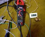
In cooling mode it was using a steady 1.3 kW of power. In heating mode, it got up over 2kW, so I just used cooling mode for testing.
Anyways, there is a terminal that can be shorted out to get in to T-Run mode.
And IIRC, there is similar function that can be accessed using the remote..
From Sanyo Manual:
How to Test Run the Air Conditioner
After turning on power to the air conditioner, use the remote
controller and follow the steps below to conduct the test run.
(1) Set the remote controller in Test Run mode.
(Fig. 59a)
a) Press and hold the ION button.
b) Then press and hold the 1HR TIMER button.
c) At the same time, press the ACL (reset) button once.
Use a pointed object such as the tip of a pen to press
the ACL button.
• After a few seconds, “ ” appears and “oP-1” blinks in
the remote controller display area.
(Fig. 59b)
d) Release the 1HR TIMER button.
e) Release the ION button.
(2) Start Cooling mode test run by pressing the ON/OFF
operation button of the remote controller. (Fig. 59a)
• This starts the fan producing uncooled forced air with
the 4 indicator lamps (OPERATION lamp, TIMER
lamp, QUIET lamp, and ION lamp) on the main unit
blinking. (Fig. 59c)
• After 3 minutes, the system shifts into cooling opera-tion, and cool air will start to be felt. Cool mode test
run is unaffected by the room temperature.
(3) Press the ON/OFF operation button of the remote con-troller again to stop the test run. (Fig. 59a)
(4) Finally press the ACL (reset) button of the remote con-troller to release it from Test Run mode to return to nor-mal mode. (Fig. 59a)
• “ ” and “oP-1” will disappear from the remote con-troller display area.
I did NOT like running this test on my first Sanyo. The power use was like using the HIGH POWER mode. Horrible.
I'm not 100% sure, but running the test mode using the remote is a full-throttle kinda test..
Thinking back on this, makes me wonder if your system is stuck in some kind of test mode.?.
When I use the T-Run jumper (with my extension switch), it ramps up fast and stays steady..
As you have seen (from your other system), an inverter mini-split will ramp up & down continuously as it runs.
Holding steady is not normal operation. (Unless they sold you a non-inverter unit).. -
Re: Sanyo mini split AC (inverter/variable speed)
12.9 for the compressor + 1 amp for the condenser fan motor= 13.9 total. Definitely looks like you have a problem, total time on max speed (130 % total output) should be no more than 15 min. before the compressor slows slightly to nameplate amps. Call your installer and have them come out and check it out while your still under the full warranty. If the company has no service experience call Mitsubishi and get a list of local contractors that went to the factory school and call one of them. -
Re: Sanyo mini split AC (inverter/variable speed)
Id dump it , pull the POS out ..STUFF IT NOW
Start again, Bettered informed
Don't let the BS replys let the warranty into time lapse , till the warranty date is over . It started the day You ordered it !!!!
We now live in a (pick yourself) *&^%$#@ marketing climate of built in obsolescence .
VT -
Re: Sanyo mini split AC (inverter/variable speed)
hey all,
sorry for the long lag time in response as to whats up with my 18000 mitusubish fe ... been so much other stuff on the plate lately.
Any way, the tech guy did come out and was on phone at my house with Mitsubishi while trying to figure out the excessive wattage draw. The procedure for testing by mitusubishi relating to execessive wattage draw was time consuming. The procedure to determin whether wattage draw was within specs was to always keep the unit with one degree setup point during the test and to see what the watt draw was every 10 minutes or so for two hours. Under this scenario the unit was sipping power.... about 3.7 amps a leg x 240 = about 950 watts. The test was done when temperature of the day was about 68 degrees. The testing protocol does not allow according Mitsubishi increasing the temperature on the theromestat to more than 2 degrees above setpoint... bottom line... it past the test... to me this is almost like shutting down the thermostat to room temperature?
This was not part of the test; but my obeservation. if you increase more than above 2 degrees; the power consumption will go up considerably and it will go to the lock motor rating for ever if it cannot get back within the 2 degree setpoint... in other words you will be drawing close to 4000 watts as long as unit vs the 1270 watts or so max the unit claims.
One thing i learned .... the amperage specifications, locked motor amps on the mitsubishi 18000 btu minute is the same specs as the mitisubishi 24,000 btu unit:
18000 unit spec for rla and lra:
RLA: 12.9 (rla - rated load amps)
LRA: 16.1 (Locked Rotor Amperes) (max current spike during a motor start)
And here is 24000 mitisubishi specs:
RLA: 12.9 (rla - rated load amps)
LRA: 16.1 (Locked Rotor Amperes) (max current spike during a motor start)
The 18000 and 24000 unit lra and rla are exactly the same... except the wattage consumption charts they use show different power consumptions.... the power consumption of the 18000 unit i have seen match exactly the power consumption of the 24000 unit... if i use the 24000 unit energy usage for my 18000 unit; it matches exactly. ...my 18000 unit energy usage specs does not match the power consumption its using.
My advice, stay away for the 18000 unit.... be far better off going with 24000 unit as im not sure your saving anything going with the 18000 other than using the same power to get less btu. Also my understaing is 24000 btu unit has more fins and thats how it gets more cooling; however, the motor/compressor is same.
As you may also recall i have a 12000 unit mitsubishi fe unit. I really like the 12000 unit... runs within specs and completely happy with it.
I have somethings others might want to considering when buying split system...
1) look for the lra and rla rating on the actual name plate;... in my case with the 18000 unit lra (lock motor rate) can be run for long period of times forever; high amount energy used and wears out compressor.
2) look for minimum circuit break size requirement... i seen some high seer 12000 btu units (26 seer or better) that required 20 amp breakers using 240 volt ...what this means is 15 amps were not enough to run these systems....consider 20 amp x 240 volt = 4800 watts.... seems something amiss here... need to research this more; but my high seer 18000 btu unit was 4800 watts for hours if not days at a time ( i shut it off though)...it required 20 amp breaker...why would a 26 or seer unit require a 20 amp breaker.... something to think about
3) some might want to take serious look at 120 volt systems ... max watt requirements if 15 amp breaker required for 120 volt system = 120 volt x 15 = 1800 watts
in closing, the 18000 mitisubishi does not meet the specs it claims.. and what i mean is actually "maximum" power requirements; ... avoid it all cost.... if i had to do over i would put two 12000 mitusubishi in place of the 18000. -
Re: Sanyo mini split AC (inverter/variable speed)
Here is the plate for my 24,000 BTU Sanyo..
Attachment not found.
It seems to be pretty close to your specs..
And this paragraph:
"This was not part of the test; but my observation. if you increase more than above 2 degrees; the power consumption will go up considerably and it will go to the lock motor rating for ever if it cannot get back within the 2 degree setpoint... in other words you will be drawing close to 4000 watts as long as unit vs the 1270 watts or so max the unit claims. "
Really rings a bell with me. My units will go nuts and try to bring down the grid, if I click for 2 degrees more heat..
One degree at a time is the only way to go. I leave them at 20C overnight, so there is no problem in the AM,
when I want to bring them back up to 21C (69.9F).
One big problem occurs at the end of a defrost cycle. During defrost, they reverse refrigerant flow, and the indoor coil temp drops really low..
When heating mode is restored, that extra cold indoor coil temperature causes a Big ramp up in power use.
Much like asking for 3 or 4 degrees of extra heat (above room temp).
My first Sanyo would go into over-load or over-pressure and power down after a defrost ramp up..
I suspect it was over-pressure, since a pin-hole leak occurred on the compressor output tube.
IIRC, they crash at about 3.6 kW.
The Fix:
I built precision 10A circuit breakers for both of my Sanyos. They have a 60 second time-out and then reconnect the 240Vac. (2.4kW max pwr allowable).
Every once in a great while, one will trigger.. And then allow the system to come on again. (In OFF/standby mode).
Running takes a while sometimes, since the IR remote only sends a command packet every 5 min.
Sometimes, it will take 2 or 3 resets, depending on the thickness of the ice, or the indoor coil temperature.. Not sure which.
But within 10 or 15 minutes, it's over and the ice is gone and the heat is flowing again..:p -
Re: Sanyo mini split AC (inverter/variable speed)
Ran across this Youtube video on the Fujitsu HFI system. Seems pretty flexible given that one can run up to 8 zones with a variety of different indoor units. It looks like with the slim-duct indoor unit one could easily retrofit this system to a conventional HVAC system while adding zoning at the same time...


 https://www.youtube.com/watch?v=orRJiutO9t0
This discussion has been closed.
Categories
- All Categories
- 229 Forum & Website
- 136 Solar Forum News and Announcements
- 1.3K Solar News, Reviews, & Product Announcements
- 179 Solar Information links & sources, event announcements
- 892 Solar Product Reviews & Opinions
- 252 Solar Skeptics, Hype, & Scams Corner
- 22.5K Solar Electric Power, Wind Power & Balance of System
- 3.5K General Solar Power Topics
- 6.7K Solar Beginners Corner
- 1K PV Installers Forum - NEC, Wiring, Installation
- 2.1K Advanced Solar Electric Technical Forum
- 5.6K Off Grid Solar & Battery Systems
- 428 Caravan, Recreational Vehicle, and Marine Power Systems
- 1.1K Grid Tie and Grid Interactive Systems
- 655 Solar Water Pumping
- 816 Wind Power Generation
- 620 Energy Use & Conservation
- 622 Discussion Forums/Café
- 316 In the Weeds--Member's Choice
- 74 Construction
- 125 New Battery Technologies
- 107 Old Battery Tech Discussions
- 3.8K Solar News - Automatic Feed
- 3.8K Solar Energy News RSS Feed