SMA SI8 SOC drops

Xale
Registered Users Posts: 8 ✭✭
Hello
I'm off grid and my Sunny Island have trouble with the SOC. Sometimes it drop from 70 to 20% without reason.
SMA online recommended a software update, but it doesn't change anything. My local retailer has no will to help
I'm not an electrician and it's difficult to deal with the parameter and understand how it works by myself.
I hope someone can help me
I'm sorry for my poor English
Best regards
Comments
-
-
Welcome to the forum Xale,
On your second graph, it shows an increase in State of Charge around midnight. Are you charging with a generator in the middle of the night (manual or automatic)?
Do you have a graph or any voltage readings of your battery bus during these times (or before and after)? Any indications of problems with the battery bank (such as loss of capacity)?
Check all battery connections that they are tight and clean?
-BillNear San Francisco California: 3.5kWatt Grid Tied Solar power system+small backup genset -
My guess is you are looking at system voltage!
I'd guess;
System voltage is affected by loads, That is the reason you see higher % during the day when you have the support of the solar array.
You see a dip sometime after, while you are still up and doing, cooking dinner, watching TV. Then when you go to bed there are less loads on your system and the system voltage rises.
In the morning, you see a slow rise in voltage as the sky lightens, but don't see a big 'jump' until the sun hits the array squarely. about 11am. (it's strong enough jump that there might have been morning clouds that cleared as well.
Voltage is a poor method of determining your system's State of Charge (SOC). It does appear that the battery bank is not reaching fully charged during the day. It's may damage your battery bank to be held in a low SOC.
It would be good to review your system sizing and settings. My guess is that at rest, measuring by voltage your battery bank is staying at or below 50% SOC. Of course, this may not be true, as system settings must be set properly.
Home system 4000 watt (Evergreen) array standing, with 2 Midnite Classic Lites, Midnite E-panel, Magnum MS4024, Prosine 1800(now backup) and Exeltech 1100(former backup...lol), 660 ah 24v Forklift battery(now 10 years old). Off grid for 20 years (if I include 8 months on a bicycle).
- Assorted other systems, pieces and to many panels in the closet to not do more projects. -
Hi, thanks for your replies.I add some details on the curves and give you some parameters. The installation and batteries have 2,5 yo.I'll check for voltage curves or measurements.If voltage variations makes troubles, is there any other way for SOC determination ?Tell if you need to check some other parameters.Best regards
-
There are 3 major methods of determining state of charge:
- Measuring specific gravity of electrolyte (flooded cell lead acid batteries). You have VRLA type? Can you measure electrolyte SG?
- Measuring Amp*Hours with a precision power resistor. The resistor is typically in the negative battery lead and the "controller/meter" measures the voltage drop across the resistor. 10 mV drop = 25 amps (made up number). 25 amps * 5 hours charging = 125 Amp*Hour of charge. Generally, the State of Charge is reset to 100% full when "something happens" (such as reaching 57.6 volts for >1 hour). Usually large/complex solar power systems (inverter-chargers and such) use the Current Shunt (precision resistor) to measure the current flow and direction over time.
- Monitoring voltage. "Bulk charge" is as much current as the charge controller can output (i.e. 100% of sun energy > charging battery bank and running loads. "Absorb Charge" is when battery voltage reaches 57.6 volts and controller holds voltage for 2-6 hours or so---Deeper discharge, 6 hours. Shallow discharge 2 hours. "Float charge" "charging voltage" drops back to 54.4 volts until sun sets and/or loads are larger than solar current).
https://www.solar-electric.com/midnite-solar-battery-hydrometer.html
https://www.amazon.com/s?k=battery+hydrometer (other types of hydrometers)
Example of a precision resistor: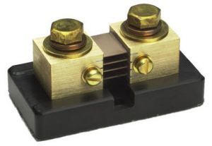
Negative battery to bus leads connect to large bolts. The controller/battery monitor "millivolt meter" wires connect to the two small screws on side.
Example of external Battery Monitor System:
https://www.solar-electric.com/victron-energy-bmv-712-smart-battery-monitor.html
My question regarding your graphs... Generally, a battery bank does not change State of Charge in big steps. When I see a big step up or down (without a huge load/charging current)--It sort of looks like a battery bank losing capacity or bad electrical connections in the battery cabling.
And in the middle of the night, seeing the battery "charging" 5% (step up in State of Charge) when you only have discharging loads--Does not make sense at all.
Checking all battery leads (and millivolt meter leads so the precision resistor) are tight and clean (no sign of browning/overheating connections, no corrosion from water/electrolyte, etc.) is my first suggestion to check (possible cause of "jump"/"drops" of State of Charge because of poor/intermittent electrical connections).
You have updated the software---I guess that your system has been working well for the last two years? Checking battery connections is my first guess (something goes wrong "quickly").
Monitoring the battery bus voltage (and telling us the battery charging setpoints/battery type/etc.) and letting us know what you see (at night with loads, during day with charging, etc.) will help us figure out if you have a "battery+wiring issue" or possibly a software/programming issue...
With these modern computer based inverter-charger systems... Besides a cold reboot (which I assume you did after the software upgrade), "Resetting to Factory Defaults" and reprogramming the system settings (battery type, capacity, etc.) can sometimes help fix a corrupted database.
-Bill
PS: I guess you are in
-BillNew Caledonia 
Province Sud Near San Francisco California: 3.5kWatt Grid Tied Solar power system+small backup genset -
it's time to discuss your system type and size of batteries and solar array.Home system 4000 watt (Evergreen) array standing, with 2 Midnite Classic Lites, Midnite E-panel, Magnum MS4024, Prosine 1800(now backup) and Exeltech 1100(former backup...lol), 660 ah 24v Forklift battery(now 10 years old). Off grid for 20 years (if I include 8 months on a bicycle).
- Assorted other systems, pieces and to many panels in the closet to not do more projects. -
Hi,I have 5kWc solar array (with 16 panels perlight 290 MB). The batteries (LPBC 200-12) are 8 lead carbon VRLA, 200Ah, for 19.2 kWh storage. Everything is managed by a SMA Sunny Island 8.0H and Sunny boy 5000 AV40. Generator 3kV, i start manually if the soc is to low or after several cloudy days.I have check the connections, no water or corrosion but i had to tighten 2 terminals... I hope that was that, even if it mean that my retailer doesn't check this ...I started to have jumps in may 2021.When i updated the software, i had to enter generator and battery parameters in November but the drops appear again one month later, 1 to 3 times a month.I had also some temperature wire warning, SMA told me to check the resistance which must be 2000 ohm at 20 ° but i don't know were the wire is. Can you show me ?My retailer told me he can plug a shunt. Is it a better way than voltage to measure SOC ?I hope i was more precise. Don't hesitate to ask me if you need more info to understand better my setup.Best regardPS : Yes i'm in new caledonia
-
Here is a document that details the battery charging/monitoring system (sorry, this is in English--Perhaps you can find a French version):
https://files.sma.de/downloads/SI_Batteriemanagement-TI-en-21.pdf
They do talk about jumps in state of charge too...4 First Remedial Actions in the Event of SOC and SOH DeviationsAnd they have a SOC trouble shooting chart...
No direct measurement is possible for estimating SOC and SOH. Therefore, the values indicated are always an estimation based on available measurable values, implemented algorithms as well as on parameter settings. A deviation in estimates of actual values is to be expected. Keep in mind that both incorrect installation and wrong parameter settings will negatively influence the accuracy of the estimation. The actual values of SOC and SOH can only be obtained through capacity tests which cannot be performed in field for most applications.
During normal operation and assuming the battery is healthy and the correct settings have been made, the jumps in SOC of less than 10% can be observed due to recalibration procedures (see section 1.2, page 2). The recalibration to a SOC of 20% and jumps of more than 10% are not likely to happen under these conditions (healthy battery and correct installation and settings). Thus, fast changes in SOC and jumps in estimated SOC values can be used as an indicator of incorrect settings, premature battery aging or battery errors.
Here is a little bit about battery bank from SMA... There is a nice chart that shows the relationships between battery bus cell voltage and State of Charge and amount of charging/discharging current:
https://files.sma.de/downloads/TECHBATT-AEN114414.pdf
I believe you have 12 volt batteries in two parallel strings (4x 12 volt batteries in series for 48 volts, with two parallel strings for 400 AH).
With parallel strings, you want to make sure they are wired correctly to share current equally. This web page explains:
http://www.smartgauge.co.uk/batt_con.html
I don't know the SMA product family--But if it does not have a Current Shunt and they can install one in the battery bank negative lead--It could help SoC accuracy. HOWEVER, even with a current shunt, they still can drift and the controller has to "reset/recalibration" the SoC based on software and charging voltage/time.
The "remote battery temperature sensor" is (typically) two wires with a NTC or PTC (negative or positive temperature coefficient resistor) sensor. At a specific temperature, it has a specific resistance... In this case, if the sensor is at 20C, it should read 2000 Ohms (you probably need to disconnect the RBTS from the SMA controller to measure the resistance). Guessing, this may be what the RBTS looks like
Another thing you can do... You have 8 "identical" batteries (12 volts @ 200 AH each). Use your volt meter to measure the voltage of each battery--Under charging, under load, and "resting". Ideally, all the batteries should be within 0.2 volts of each other (or less). If you see one or several batteries with "higher or lower" voltage than the rest--Need to figure out why.
If you see one battery that is low or higher than the others--That could indicate that battery (or its wiring) is having issues.
For example, if you see one battery that is >0.2 volts lower than the others--That may indicate that the batteries need to be equalize charged--Basically "over charging" the battery bank to bring all batteries up to 100% charge for all of them.
It is possible that your VRLA batteries should not be EQ Charged--Do you have a link to a battery manual for your set?
Are they something like these batteries?
https://www.alibaba.com/product-detail/High-Efficiency-Lead-Carbon-Battery-LPBC200_1600271104062.html
These batteries have fairly low charging voltage:
13.80-14.10V or 55.2 to 56.4 VDC for Absorb/Charging set-point
-Bill
Near San Francisco California: 3.5kWatt Grid Tied Solar power system+small backup genset -
Hello,Thanks for the batterie management sheet. The problem with SMA, is, when you send parameters and setting they told you everything is OK.For exemple when i ask if lead batteries can be equalised (because someone told me it shouldn't) their reply was : everything is set as intended.Same for a low lvl 3 SOC limit (20%) before shut off, everyone told me that lead batteries doesn't like deep discharged but the setting allow to go so deep.I don't have enough knowledge about solar system and electiricty, thus i have to trust SMA says even if it seem to be counter intuitiv.I'll check the voltage in different situation and told you.This is my batteries :

-
It would be nice to see that float and charging voltage on the side of the battery (label has been damaged)... Here is a quick Lead Carbon spec sheet from Victron:
https://www.victronenergy.com/upload/documents/Datasheet-Lead-carbon-battery-EN.pdf
Recommended charge voltage
Float Service Cycle Service Absorption 14,1 - 14,4V
Float 13,5 - 13,8 V 13,5 - 13,8 V
Storage 13,2 - 13,5 V 13,2 - 13,5 V
They don't talk about EQ charging--At at the "lower" charging voltage (14.1-14.4 volts), that is similar to AGM and other sealed lead acid batteries that say do not do elevated voltage EQ Charging.
If I needed to do "EQ charging" (i.e., the 12 volt batteries are >0.2 volts different between batteries resting voltage), I would try holding 14.1-14.4 volts for >8 hours (typically once every 6 months). That seems to be a useful and "gentle" EQ charging for sealed/agm/gel/etc. batteries.
The reason for minimum SoC of 20%--The problem with most rechargeable batteries is that if you take a cell to zero volts or even negative voltage ("reverse charging" a weak cell because the other strong cells can still supply discharge current) is that "reverse charging" voltage will generally ruin that cell--And therefore ruin the whole battery (in a 6 cell x 12 volt battery).
With Lead Acid batteries, that 20% floor on SoC--Allows room for strong and weak cells to be discharged, without taking the "weak cell" into negative voltage "reverse charging".
Lead Acid batteries will not last as long if taken to low SoC values (say less than 50% SoC)--But they will not be ruined as long as they are recharged in the next day. More or less, taking a lead acid battery to 50% to 20% SoC is like 2-3x discharge cycles of life vs taking a Lead Acid battery to 75% SoC overnight. I.e., a 75% SoC discharge cycle lasts (made up numbers) 2,400 cycles but a 25% SoC discharge will last 800 very deep cycles. I.e., 75% SoC => 2,399 cycles left; a single 20% SoC cycle => 2,397 75% cycles left.
Anyway--Seeing the voltages of each 12 volt battery as you use them will be helpful in understanding the "health" of your battery bank.
-Bill
Near San Francisco California: 3.5kWatt Grid Tied Solar power system+small backup genset -
Hello,I'll check for another sticker for the batteries.unfortunately this night i had jumps, a fall to 20 % at 1 am and a jump from 20 to 33 % at 3am. Then other jumps to reach full charge in the morning.I've measured voltage in different situation during this day :
paralell serie série SOC 1 2 3 4 5 6 7 8 time Shut off 20 % SOC 12,32 12,33 12,33 12,22 12,33 12,32 12,35 12,28 01:00:00 Sun charging 2100W 40 % SOC 13,12 13,15 13,08 13,07 13,08 13,07 13,09 13,15 09:00:00 Storage charge 100 W 96% SOC 13 13,01 12,97 12,98 12,98 12,97 12,95 12,99 15:00:00 Discharge 500w night 86% SOC 12,27 12,52 12,43 12,49 12,48 12,28 12,26 12,28 19:00:00 Tell me what you think of that and if i need to do some more tests.Best regards -
Between 9:00 and 13:00 ... What is the charging voltage (per battery, overall... i.e., 14.0 volts per battery, 56.0 volts overall)
The battery voltage spread is not great--But I do not see a "bad battery" from your voltage readings (all voltages are fairly close to each other).
.
What I do not see is in the middle of the day around (typical sealed battery charging voltage) 14.2 to 14.4 volts per battery (56.8 to 57.6 volts overall). Ideally you want to see that "charging voltage" held for around 2-6 hours during the middle of the day.
The batteries need to be >>13.5 to 13.8 volts (float) to actually be charging.
And the charging current from your array--How much during daytime?
For example--The typical maximum charging current I would expect:- 5,000 Watt array * 0.77 panel+controller derating * 1/56.8 volts charging = 68.8 amps (best charging current on cool/clear day with discharged battery bank)
You should be seeing at least 1/2 that charging current (discharged bank, middle of day, sunny weather) on average or at least 34 Amps. If you see much less charging current "on average" in full sun, I would start to wonder if the solar array+charge controller is working correctly.- 68.8 Amps "best charging current" * 1/2 = 34.4 Amps typical to a bit low "average" charging current maximum
- 400 AH * 0.05 rate of charge = 20 Amps minimum charging current during day (discharged batteries)
- 400 AH * 0.10 rate of charge = 40 Amps nominal charging current
- 400 AH * 0.13 rate of charge = 52 Amps typical maximum rate of charge
Note that AC Current Clamp meters are very common with electricians, but we need an AC+DC current clamp meter to measure the DC current in the solar+battery+DC Wiring. Examples of AC+DC Clamp Meters:
https://www.amazon.com/gp/product/B00O1Q2HOQ ("inexpensive" AC+DC clamp meter)
https://www.amazon.com/gp/product/B019CY4FB4 ("mid priced" AC+DC clamp meter)
It would be nice to see nice graphs of battery charging:- Bulk: Battery bus voltage below 57.6 volts, charging in full sun--Maximum current from array (less than 80% State of charge)
- Absorb: Battery bus voltage at 57.6 volts, charging current limited by battery bank for 2-6 hours (roughly 80% to 99% SoC)
- Float: Battery bus voltage at 54.x volts battery 100% charged, still sunny, solar supplying current to DC loads and keeping battery from discharging
-Bill
Near San Francisco California: 3.5kWatt Grid Tied Solar power system+small backup genset -
Hello,This is a picture of the full battery sticker
 I don't if it can help but i have an "instantaneous value" in software it show some of these parameter :
-
The 67.1C battery temperature is way too high (either impossibly high--Or your batteries are "cooked" if real). Your bank should be 25C to maybe 35C range (warm days/tropical climate). Lead Acid batteries do not like high temperatures (the age faster).
There appears to be an issue with the Remote Battery Temperature sensor (poor wiring connections, bad sensor, some hardware/software issue inside the inverter???).
If the sensor reading is wrong/intermittent--That could certainly cause those SoC jumps/confusion in the inverter (I would guess).
-BillNear San Francisco California: 3.5kWatt Grid Tied Solar power system+small backup genset -
Hello,My fitter set a shunt wednesday.
 But the next day jumps appears again.
 It seems that there is no temperature sensor. I'm still waiting explanation from my fitter.
 -
I'd be worried about a heat generating resistor ( shunt ) in an enclosed plastic box. Perhaps it does not get very warm ?
Powerfab top of pole PV mount | Listeroid 6/1 w/st5 gen head | XW6048 inverter/chgr | Iota 48V/15A charger | Morningstar 60A MPPT | 48V, 800A NiFe Battery (in series)| 15, Evergreen 205w "12V" PV array on pole | Midnight ePanel | Grundfos 10 SO5-9 with 3 wire Franklin Electric motor (1/2hp 240V 1ph ) on a timer for 3 hr noontime run - Runs off PV ||
|| Midnight Classic 200 | 10, Evergreen 200w in a 160VOC array ||
|| VEC1093 12V Charger | Maha C401 aa/aaa Charger | SureSine | Sunsaver MPPT 15A
solar: http://tinyurl.com/LMR-Solar
gen: http://tinyurl.com/LMR-Lister , -
For a random 500 amp @ 50 mVolt shunt:
https://www.solar-electric.com/search/?q=current+shunt- Power = Volts * Current = 0.050 volts * 500 Amps = 15 Watts (at full rated current)
- P=I^2 * R;
- R = P / I^2 = 15 Watts / (500 Amps)^2 = 0.00006 Ohms
P = I^2 * R = (50 amps)^2 * - P = I^2 * R = (50 amps)^2 * 0.00006 Ohms = 0.15 Watts
-BillNear San Francisco California: 3.5kWatt Grid Tied Solar power system+small backup genset -
The "jumps" can still be from intermittent Temperature Sensor... If no external sensor, then should be an internal "default" temperature sensor inside inverter-charger or solar charge controller...
And the question--Looking at the inverter-charger setup--The shut is properly configured and "operating" with system?
-BillNear San Francisco California: 3.5kWatt Grid Tied Solar power system+small backup genset -
Did you solve the issue? I am getting the following message on my SI system:A 20% recalibration of battery state of charge executed with a leap greater than 10%I have worked through all the obvious things (i.e. battery configuration, temperature sensor etc).


Categories
- All Categories
- 229 Forum & Website
- 136 Solar Forum News and Announcements
- 1.3K Solar News, Reviews, & Product Announcements
- 179 Solar Information links & sources, event announcements
- 892 Solar Product Reviews & Opinions
- 252 Solar Skeptics, Hype, & Scams Corner
- 22.5K Solar Electric Power, Wind Power & Balance of System
- 3.5K General Solar Power Topics
- 6.7K Solar Beginners Corner
- 1K PV Installers Forum - NEC, Wiring, Installation
- 2.1K Advanced Solar Electric Technical Forum
- 5.6K Off Grid Solar & Battery Systems
- 428 Caravan, Recreational Vehicle, and Marine Power Systems
- 1.1K Grid Tie and Grid Interactive Systems
- 655 Solar Water Pumping
- 816 Wind Power Generation
- 620 Energy Use & Conservation
- 622 Discussion Forums/Café
- 316 In the Weeds--Member's Choice
- 74 Construction
- 125 New Battery Technologies
- 107 Old Battery Tech Discussions
- 3.8K Solar News - Automatic Feed
- 3.8K Solar Energy News RSS Feed