Help connecting inverter to sub panel with ATS

BigCali
Registered Users Posts: 10 ✭✭
Hi I need your help...
I plan on using a 50a TS and connecting my main panel of the house to the TS with a 50a circuit breaker and connecting my inverter to the TS and out to my sub panel where I plan on powering 6 circuits (110v only) that I relocated from my main panel that I want to be ran of my battery bank.
All I did was relocate the circuit breaker wires itself, not the common or ground, cause I have my sub panel grounded to an 8ft grounding rod so idk if that’s all I’m suppose move over since I’m installing a TS that will provide the common wire connection depending on where the current is coming from (from main panel of the house or my inverter).
But I’m mainly confused on do I connect all my grounds together in the TS? My head is spinning cause I’ve come across all kinds of information that contradicts itself about combining different grounds together like from a house and from sub panels that are connected to grounding rods 🤯..lol..
hhmmmm now I’m wondering if I remove the ground from my sub panel that connects to my grounding rod and instead connect the ground that comes from the TS which comes from the main panel of the house... would that work? 🤔
Please I really need your guidance and wisdom fellas regarding this confusion I’m having. I don’t want to damage my inverter or my main panel to the house. Thank you so much for your time and any information you share with me 🙏🏼
Big Cali
Comments
-
Big Cali,
Welcome to the forum... And I have moved your first post to the general solar topic.
Also, you only need to post once--We are a small forum and everyone pretty much sees all the posts. And having multiple same/similar posts--It makes for scattered replies in multiple discussions.
I formatted your post a bit... A "wall of technical/complicated" text is a bit difficult to follow/reply to,
Give me/us a bit of time to read your post and have some (hopefully) useful replies.
Take care,
-BillNear San Francisco California: 3.5kWatt Grid Tied Solar power system+small backup genset -
Thank you my friend 🙌🏼
-
Your description is somewhat confusing, is the intent to power a sub panel, fed from the main distribution via a 50A breaker through the prime input of an ATS, with the inverter feeding the into the alternate input?
For informational purposes, there is reference to ground there should be a single grounding point at the main distribution, all other conductors connected to the ground are referred to as bonding, the neutral is also bonded to ground at the main distribution. There should be only a single neutral ground bond within a system or dwelling. This does not apply to out buildings over a certain distance away, as outlined in the electrical code applicable, where it may be required to establish a second ground without the neutral bonded to it and eliminating the ground bond to the main distribution to eliminate the possibility of it becoming a secondary ground point.
NOTE: This is only a general outline always refer to the electrical code applicable to the authority having durisdiction
When it comes to an alternate energy source, such as an inverter, it should have its independent ground and neutral bonding, additionally the feed from the main distribution should be disconnected at the ATS, both live and neutral.
1500W, 6× Schutten 250W Poly panels , Schneider MPPT 60 150 CC, Schneider SW 2524 inverter, 400Ah LFP 24V nominal battery with Battery Bodyguard BMS
Second system 1890W 3 × 300W No name brand poly, 3×330 Sunsolar Poly panels, Morningstar TS 60 PWM controller, no name 2000W inverter 400Ah LFP 24V nominal battery with Daly BMS, used for water pumping and day time air conditioning.
5Kw Yanmar clone single cylinder air cooled diesel generator for rare emergency charging and welding. -
Big Cali,
The answers really depend on the details of your needs/installation. For example, there are AC Off Grid Inverters that have their own internal transfer switch--And you can take a standard AC inverter (or even genset) and connect to your sub-panel for backup power.
First... What is grounding. Grounding is tying all the metal boxes (AC panels, electrical J-boxes, water plumbing, gas plumbing, sinks, etc.) together with the "Green Wire" ground. This is to both ensure if there is a short to ""something" metal, that that piece of metal has a connection back to the "power source" (main panel, genset, utility power, AC inverter, etc.) and shunt that current to the power return (DC Negative ground, Ground bonded neutral in the USA) and pop a fuse/circuit breaker. The grounding is also there for shunting lightning energy to "ground" too.
Next.. The above says that the green wire needs to shunt the energy to the "return" of the energy source. With DC wiring, that is (typically) tying the Negative battery terminal or Ground Bus to the "chassis ground" of a car/RV/trailer. You put fuses/breakers in the positive wires leading from the positive bus (sized based on the AWG of the wiring--Fuses/breakers are there to protect the wiring, not the "devices/loads").
For North American Power systems... We have 120/240 VAC 60 Hz split phase power... What is that? Think of a transformer with L1 and L2 leads... And a "center tap" (Neutral) in the middle of the transformer. You get 240 VAC from L1 to L2, and 120 VAC from L1 to neutral or from L2 to neutral). Again in N.A. power, we tie (bond) the AC Neutral to the Green Wire grounding (typically in the main panel for homes, sometimes in the AC inverter or the Genset--Typically, less than ~3,000 Watts have their AC neutral "floating", and larger units tend to have their AC neutral bonded to chassis/frame ground in the inverter/generator). When you Ground Bond the Neutral, you only need to put your breakers in the L1/L2/+ DC terminals. No fuse/breaker in the neutral wiring (and not needed as the neutral always is at "zero volts" because of the neutral+ground bonding.
The above takes care of short circuits for the AC and DC power... Any short finds its way through the ground wire/conduit back to the "return" Neutral/DC Negative terminals--Popping the breaker/fuse.
Ground Rods--They are not there to provide 12 VDC/120 VAC grounding. They are typically pretty high resistance (NEC is typically 25 Ohms to earth (dirt) maximum). At 120 VAC that is only (120v/25o= ) 4.8 amps. Not enough to even trip a 15 amp 120 VAC breaker on a normal home circuit.
Ground Rods are there to provide a path for lightning strikes (xx,000,000 volts--25 Ohms is not going to slow anything down). Generally, if you are in a home--If you need multiple ground rods (lightning needs short/relatively straight paths from strike point such as a solar panel frame to the ground rod, right at the base/outside wall of the structure). If your panels are 40 feet away, then you would want a second ground rod for lightning path to "earth". However, to provide "electrical safety" (xx VDC, 120/240 VAC), you want to tie all the ground rods together with (typically) a minimum of 6 AWG solid wire--So that a short circuit at the "remote" thing (such as at the solar array/frame and a shorted security light) can find its way back to the main panel AC Neutral/Green wire ground bond (you don't want a solar framework to become hot, and somebody walking through wet grass get electrocuted if they grab the frame).
So--The above talks about the "green wire" grounding and the "single point" AC neutral/ground bond.
Next, the AC neutral (and DC Grounding)--The "return" wires are there to conduct the current (return flow) from the "hot" leads (L1, L2, DC +). Could you have multiple Neutral+Ground bonds (such as a N+G bond in main panel, and in the Genset electrical box)--The first answer is sort of "yes" you could. However it is to be avoided form multiple reasons. The NEC (and general electrical design) is taking multiple reasons into account. The first--No load current flow through the green wire ground/conduit. It is a "backup" electrical path for short circuit current. If you have multiple current paths, you could "over current" a segment, or even overheat an electrial box (if you put AC current "out" through one knockout, and the "return"/ground current through a second knockout--That is like a transformer and causes "circulating current" in the sheetmetal of the box--and can overheat).
Another big reason is because we are using GFI (Ground Fault Interrupter) outlets and circuit breakers. GFIs can and does save lives where a person grabs an electrical appliances (drill, blender), and puts the other hand in the sink water, or steps in a puddle. The GFI measures the current between Lx and Neutral--If the current Lx=N, then all is OK. If there is more than 5-10+ mAmps of "difference"--It is assumed that there is an alternate flow of current and trips the GFI (through a person, an extension cord falls in the pool, etc.).
If you have (for example) a generator with GFI outlet, and plug that into the home (through a transfer switch) and connect to your main panel. A larger genset has N+G (frame) ground in the generator, carries L1+L2+N+G to the main panel, which also has N+G bond in the panel... This allows current flow through both N and G wiring... And if you have a GFI in the genset, the genset GFI will trip open.
There also have been reports where N+G in genset plus N+G in home causing generator voltage regulation to fail... Don't know if that was the cause--But recommend not doing this.
Now to address N and G with an ATS/TS... Recreational vehicles are a very common source of confusion... You have Shore Power (N+G back at the RV park AC power). You have a backup Genset (N+G Bond?), and an AC inverter (N+G Bond?) and the AC panel in the RV (typically no N+G bond)--Some transfer switches will switch L1+L2+N leads, not G. This is done so that, for example, "lift" RV N+G bond when running from shore power. And connecting N+G when running from Genset or AC inverter.
Back to the hardware--What ATS do you have an can it "switch" the AC Neutral? Typically, the switch would transfer from AC Main panel (L1+N and carry ground through) to AC inverter (L1+N plus ground). In this case, we either assume (verify) that N+G bond inside inverter, or your run a separate N+G bond on the "inverter side" of the electrical system.
You might also wish to decide if you want a manual or automatic transfer switch for a backup AC genest too for that subpanel (use a cord for physical transfer, or a second transfer switch (as an example--And you need to check N+G bonding for both inverter and genset to make sure they are compatible).
Your thoughts?
-BillNear San Francisco California: 3.5kWatt Grid Tied Solar power system+small backup genset -
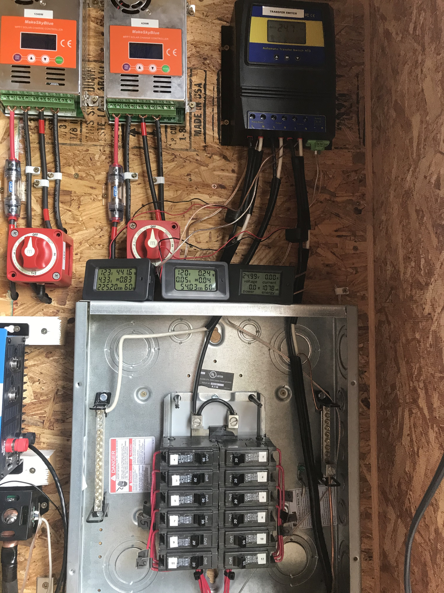
Thank you so much for the feed back & knowledge 💯 I have my solar set up about 10ft away from my main panel of the house in a Tough Shed. I’m wanting to use my inverter from my battery bank as the primary and the grid from my main panel of the house as back up. I have a MOES 50A Automatic Transfer Switch. When the ATS is on grid mode, the house has power and everything is 120v is running fine... but when the ATS transfers to inverter mode, everything in the house then shuts off 🤷🏻♂️ I don't understand why if it shows that the inverter is providing 120v just like the grid does... I even went as far as checking all the circuit breakers in the sub panel and they all show 120v 🤯🤯🤯🤯🤯🤯😤😤😤 I'm so confused, I was thinking of maybe running a common wire from my main panel from the house and connecting it directly to my sub panel that way it’s always making contact no matter which mode the ATS is on and maybe that might complete my electric current from my inverter to power my house but now I’m just guessing at this point.. I’ve added a couple of pictures to give a better idea of the way I got my sub panel wired up. If you notice that I am missing a connection to complete the circuit flow of electricity please let me know

-
 So if I understand correctly, all the loads connected to the sub panel need to be powered by the inverter, until such time the batteries can no longer provide support, then the inverter shuts down thus transferring to grid power.
Should this be the case, the inverter becomes the primary source and the grid is the backup, so you need to switch the grid power to the inverter input of the ATS and the inverter power to the public power input of the ATS. Rationale is, usually the inverter is used as backup to the grid, you're using it in reverse, though this doesn't explain why the power to the house would be lost, because it's merely a branch circuit feeding into a disconnect.
It's actually a very simple concept, which I actually use to divert energy between two offgrid systems, I would advise not to introduce a second grid feed to the output of the ATS as this most likely result in damage the inverter.
If possible draw a sketch of how it wired and post it, or if needed I can draw how it should be wired.
1500W, 6× Schutten 250W Poly panels , Schneider MPPT 60 150 CC, Schneider SW 2524 inverter, 400Ah LFP 24V nominal battery with Battery Bodyguard BMS
Second system 1890W 3 × 300W No name brand poly, 3×330 Sunsolar Poly panels, Morningstar TS 60 PWM controller, no name 2000W inverter 400Ah LFP 24V nominal battery with Daly BMS, used for water pumping and day time air conditioning.
5Kw Yanmar clone single cylinder air cooled diesel generator for rare emergency charging and welding. -
Where did I go wrong??🤔🧐🤔 If I left anything out or unexplained please let me know, I tried to go as much in detail as I could. Yes plz that would greatly appreciated if you would draw out the correct way my system should be connected

-
Looking at the diagram it becomes clear why it doesn't work, the inverter neutral is isolated upon transfer thus relying on the ground, or soil assuming the main has it's own ground rod and is neutral ground bonded. In order to provide a diagram that would be functional, some questions need to be answered. Regarding the house main distribution, is the 50A breaker the main disconnect or a branch circuit disconnect as 50A seems small for anything other than a very old house, can you take a picture of the main distribution and post it? Is the intent to power the entire house?
This sort of installation could required an electrical permit, depending on where you're located and may impact an insurance claim if applicable.1500W, 6× Schutten 250W Poly panels , Schneider MPPT 60 150 CC, Schneider SW 2524 inverter, 400Ah LFP 24V nominal battery with Battery Bodyguard BMS
Second system 1890W 3 × 300W No name brand poly, 3×330 Sunsolar Poly panels, Morningstar TS 60 PWM controller, no name 2000W inverter 400Ah LFP 24V nominal battery with Daly BMS, used for water pumping and day time air conditioning.
5Kw Yanmar clone single cylinder air cooled diesel generator for rare emergency charging and welding. -
The 50amp circuit breaker that goes to the MOES ATS is located in the far left corner and the 20amp circuit breakers that I transferred over to the sub panel are the ones that are down

-
The 100A breaker on the right I would assume is the main disconnect, can you remove the front cover and take a picture? Those breakers are oddball, which would indicate they are old, for now DO NOT attempt backfeeding the main panel you could have serious problems or fire, if my assumptions on what you have done are correct.
1500W, 6× Schutten 250W Poly panels , Schneider MPPT 60 150 CC, Schneider SW 2524 inverter, 400Ah LFP 24V nominal battery with Battery Bodyguard BMS
Second system 1890W 3 × 300W No name brand poly, 3×330 Sunsolar Poly panels, Morningstar TS 60 PWM controller, no name 2000W inverter 400Ah LFP 24V nominal battery with Daly BMS, used for water pumping and day time air conditioning.
5Kw Yanmar clone single cylinder air cooled diesel generator for rare emergency charging and welding. -

-
Can you plz draw me out how it should be wired
-
The red wires coming from the sub panel are they the ones spliced with the yellow wire caps and feeding selected branch circuits? Or are you trying to power the entire house? Information needed to draw a diagram.1500W, 6× Schutten 250W Poly panels , Schneider MPPT 60 150 CC, Schneider SW 2524 inverter, 400Ah LFP 24V nominal battery with Battery Bodyguard BMS
Second system 1890W 3 × 300W No name brand poly, 3×330 Sunsolar Poly panels, Morningstar TS 60 PWM controller, no name 2000W inverter 400Ah LFP 24V nominal battery with Daly BMS, used for water pumping and day time air conditioning.
5Kw Yanmar clone single cylinder air cooled diesel generator for rare emergency charging and welding. -
Yes the red wires coming from the sub panel are the ones spliced with the yellow wire caps and are feeding the selected branch circuits 👍🏼
-
Your panel is wired "poorly". You have taken a 240 split phase panel, and installed a jumper between L1 & L2, to enable getting 120VAC at all breakers. This also can overheat the neutral wire in the panel, as it's expecting some of the load to be mirrored and zeroed out by properly balanced load splitting.
And it's likely the ATS is looking for 240VAC, and there is the issue with grounding
Powerfab top of pole PV mount | Listeroid 6/1 w/st5 gen head | XW6048 inverter/chgr | Iota 48V/15A charger | Morningstar 60A MPPT | 48V, 800A NiFe Battery (in series)| 15, Evergreen 205w "12V" PV array on pole | Midnight ePanel | Grundfos 10 SO5-9 with 3 wire Franklin Electric motor (1/2hp 240V 1ph ) on a timer for 3 hr noontime run - Runs off PV ||
|| Midnight Classic 200 | 10, Evergreen 200w in a 160VOC array ||
|| VEC1093 12V Charger | Maha C401 aa/aaa Charger | SureSine | Sunsaver MPPT 15A
solar: http://tinyurl.com/LMR-Solar
gen: http://tinyurl.com/LMR-Lister , -
This is the way I would wire the ATS, the inverter becomes the prime source (public power), should the inverter shut down for any reason the ATS will transfer to grid power, which would technically become the backup source.
Because the ATS switches the neutral as well as the line, a new neutral ground bond needs to be established at the inverter output, the main distribution ground rod or separate rod can be used, remove any neutral ground bonding in the sub panel.
When shifting the loads from the main distribution it is important to include the neutrals associated with them, or it won't work. The desired method would be to remove the entire cable from the main distribution. There are two reasons for this, splices are not usually allowed within a distribution and more importantly having two separate sources within a raceway or enclosure is bad practice, they would definitely violate Canadian electrical code rules and most likely NEC as well. Should the cables be too short to reach the sub panel, make splices in a junction box to extend them.
Label the sub panel clearly as being fed by an inverter not the grid, both inside and out, someone other than you may work on it in the future and would appreciate the heads up.
1500W, 6× Schutten 250W Poly panels , Schneider MPPT 60 150 CC, Schneider SW 2524 inverter, 400Ah LFP 24V nominal battery with Battery Bodyguard BMS
Second system 1890W 3 × 300W No name brand poly, 3×330 Sunsolar Poly panels, Morningstar TS 60 PWM controller, no name 2000W inverter 400Ah LFP 24V nominal battery with Daly BMS, used for water pumping and day time air conditioning.
5Kw Yanmar clone single cylinder air cooled diesel generator for rare emergency charging and welding. -
You are welcome, but please read the text, being sure to follow directions, as an electrican I can say that there is nothing worse than being caught by supprise by installations that do not confirm to rules outlined in the electrical code.
There are things that could enhance your system that I can see, things that could avoid potential problems, they could easily incorporated now or at a later date, if interested ask.1500W, 6× Schutten 250W Poly panels , Schneider MPPT 60 150 CC, Schneider SW 2524 inverter, 400Ah LFP 24V nominal battery with Battery Bodyguard BMS
Second system 1890W 3 × 300W No name brand poly, 3×330 Sunsolar Poly panels, Morningstar TS 60 PWM controller, no name 2000W inverter 400Ah LFP 24V nominal battery with Daly BMS, used for water pumping and day time air conditioning.
5Kw Yanmar clone single cylinder air cooled diesel generator for rare emergency charging and welding. -
@mcgivor will do 💯 Thank you 🙏🏼

Categories
- All Categories
- 233 Forum & Website
- 140 Solar Forum News and Announcements
- 1.3K Solar News, Reviews, & Product Announcements
- 181 Solar Information links & sources, event announcements
- 894 Solar Product Reviews & Opinions
- 252 Solar Skeptics, Hype, & Scams Corner
- 22.5K Solar Electric Power, Wind Power & Balance of System
- 3.5K General Solar Power Topics
- 6.7K Solar Beginners Corner
- 1K PV Installers Forum - NEC, Wiring, Installation
- 2.1K Advanced Solar Electric Technical Forum
- 5.6K Off Grid Solar & Battery Systems
- 428 Caravan, Recreational Vehicle, and Marine Power Systems
- 1.1K Grid Tie and Grid Interactive Systems
- 656 Solar Water Pumping
- 816 Wind Power Generation
- 621 Energy Use & Conservation
- 623 Discussion Forums/Café
- 316 In the Weeds--Member's Choice
- 74 Construction
- 125 New Battery Technologies
- 108 Old Battery Tech Discussions
- 3.8K Solar News - Automatic Feed
- 3.8K Solar Energy News RSS Feed