Over voltage issue

davidnolen
Registered Users Posts: 8 ✭✭
Hello all. New to solar and to this forum. So I’m having some issues with my setup and can’t get it figured out at all. The issue I’m having is my pwm30cc renogy pulse width modulation solar charge controller from what I can tell is showing over voltage. And so is my inverter because the light on it lights up and it kills the power to my light overhead lights. The battery light also flashes. Once I disconnect the panels all is fine. The lights are only 3 leds hooked up to the inverter. I have the panels plugged into the panel spots. The battery leads hooked into the battery bank and the middle battery holes. And then the inverter connected to the battery bank. Very crude but it seems to follow all the proper gauge regulations. 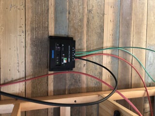
Setup:
(4) 100 watt renogy panels in parallel
1000 watt renogy inverter
pwm30cc renogy pulse width modulation solar charge controller manual
(6) 18 amp hour batteries in parallel
(4) 100 watt renogy panels in parallel
1000 watt renogy inverter
pwm30cc renogy pulse width modulation solar charge controller manual
(6) 18 amp hour batteries in parallel
Comments
-
Do you have a volt meter ?
That 1,000w inverter is going to self-consume more power than your LED lights. It could be consuming so much that your batteries are being drained, causing the shutdown.
400W of well aimed pv = 300w of harvest for 4 hours. 1200wh daily harvest 20A solar peak amps, needs 10Ga wire
108ah of 12v battery = 648wh usable battery @50%,
1,000w inverter [No Load Current Draw: < 1A]
if we call it .9A @ 12V = 11w x 24 hr = 264watt hours a day consumed by inverter, about 1/3 of your harvest.
Powerfab top of pole PV mount | Listeroid 6/1 w/st5 gen head | XW6048 inverter/chgr | Iota 48V/15A charger | Morningstar 60A MPPT | 48V, 800A NiFe Battery (in series)| 15, Evergreen 205w "12V" PV array on pole | Midnight ePanel | Grundfos 10 SO5-9 with 3 wire Franklin Electric motor (1/2hp 240V 1ph ) on a timer for 3 hr noontime run - Runs off PV ||
|| Midnight Classic 200 | 10, Evergreen 200w in a 160VOC array ||
|| VEC1093 12V Charger | Maha C401 aa/aaa Charger | SureSine | Sunsaver MPPT 15A
solar: http://tinyurl.com/LMR-Solar
gen: http://tinyurl.com/LMR-Lister , -
Is this the manual?
https://www.renogy.com/template/files/Manuals/10A-30A-PWM-Solar-Charge-Controller-Manual.pdf
The left LED/solar panel blinks if the Vpanel input is >42 volts... Most "12 volt" panels are Vmp~18 volts and Voc~22 volts (max power, open circuit). Is that the one blinking?
The battery light only seems to flash when the battery is full (red for low battery, etc.).
The inverter can shutdown if over voltage (>~15.0 to >16.0 volts). And it will also shutdown if under voltage (most will shutdown around 10.5 volts or so, and need to either have DC power cycled or battery voltage >12.5 volts or so).
So, having a voltmeter is going to be a big help here (measure panel voltage, and battery voltage).
And some other technical suggestions... Ideally, the charge controller wires should be connected diagonally to the battery bank like you did for the inverter (not your issue here):
http://www.smartgauge.co.uk/batt_con.html
I am not a big fan of putting a lot of batteries in parallel... Makes it difficult to find "weak" or problematic batteries with a volt meter--All batteries measure the same bus voltage.
I prefer to use (for example) 2x 10⁸ AH @ 6 volt batteries in series.. Or a single 12 volt @ ~108 AH battery. This way, you can measure (for example) the voltage of each 6 volt battery to make sure everything is "balanced" (both batteries in series should be 1/2 the overall battery bus voltage).
If you ever decide to go larger--2x 6 volt @ 200 AH "golf cart" batteries in series for a 12 volt @ 200 AH battery bank is a pretty respectable setup for lights.
And, look at 12 VDC LED lights... As mike says, a good amount of energy is (probably) being wasted by the AC inverter (make sure the AC inverter is off--The inverter can drain your bank during cloudy weather/winter if there is no sun.
https://www.amazon.com/s?k=12+volt+led+lights&crid=3B7OMFDM13Y53&sprefix=12+volt+LED+,aps,350&ref=nb_sb_ss_ts-a-p_1_12
There are a lot of options out there... The down side with 12 volt loads is that takes some heavier copper wiring to send significant amounts of power any larger distances. For example, say you want to send 12 VDC @ 1 amp (12 watts) with a maximum of 0.5 volt wiring drop:
https://www.calculator.net/voltage-drop-calculator.html?material=copper&wiresize=8.286&voltage=12&phase=dc&noofconductor=1&distance=100&distanceunit=feet&eres=1&x=26&y=28
Sending 1 amp for LED lighting for 100 feet with 14 AWG wire:Result
Voltage drop: 0.51
Is not bad... If you are trying to send more power (current)--Then 120 VAC from the AC inverter works much better.
Voltage drop percentage: 4.21%
Voltage at the end: 11.49
-BillNear San Francisco California: 3.5kWatt Grid Tied Solar power system+small backup genset -
I thought that could be the case. However I constantly check it with a volt meter and the batteries have never dipped below 12.3 voltsmike95490 said:Do you have a volt meter ?
That 1,000w inverter is going to self-consume more power than your LED lights. It could be consuming so much that your batteries are being drained, causing the shutdown.
400W of well aimed pv = 300w of harvest for 4 hours. 1200wh daily harvest 20A solar peak amps, needs 10Ga wire
108ah of 12v battery = 648wh usable battery @50%,
1,000w inverter [No Load Current Draw: < 1A]
if we call it .9A @ 12V = 11w x 24 hr = 264watt hours a day consumed by inverter, about 1/3 of your harvest. -
Yes. That is the manual. I have tried to to read and understand it but I just don’t get it. According to renogy I need atleast 100ah to make the inverter work as it properly should. So with that said I have absolutely no idea what to do or how to get it to work.BB. said:Is this the manual?
https://www.renogy.com/template/files/Manuals/10A-30A-PWM-Solar-Charge-Controller-Manual.pdf
The left LED/solar panel blinks if the Vpanel input is >42 volts... Most "12 volt" panels are Vmp~18 volts and Voc~22 volts (max power, open circuit). Is that the one blinking?
The battery light only seems to flash when the battery is full (red for low battery, etc.).
The inverter can shutdown if over voltage (>~15.0 to >16.0 volts). And it will also shutdown if under voltage (most will shutdown around 10.5 volts or so, and need to either have DC power cycled or battery voltage >12.5 volts or so).
So, having a voltmeter is going to be a big help here (measure panel voltage, and battery voltage).
And some other technical suggestions... Ideally, the charge controller wires should be connected diagonally to the battery bank like you did for the inverter (not your issue here):
http://www.smartgauge.co.uk/batt_con.html
I am not a big fan of putting a lot of batteries in parallel... Makes it difficult to find "weak" or problematic batteries with a volt meter--All batteries measure the same bus voltage.
I prefer to use (for example) 2x 10⁸ AH @ 6 volt batteries in series.. Or a single 12 volt @ ~108 AH battery. This way, you can measure (for example) the voltage of each 6 volt battery to make sure everything is "balanced" (both batteries in series should be 1/2 the overall battery bus voltage).
If you ever decide to go larger--2x 6 volt @ 200 AH "golf cart" batteries in series for a 12 volt @ 200 AH battery bank is a pretty respectable setup for lights.
And, look at 12 VDC LED lights... As mike says, a good amount of energy is (probably) being wasted by the AC inverter (make sure the AC inverter is off--The inverter can drain your bank during cloudy weather/winter if there is no sun.
https://www.amazon.com/s?k=12+volt+led+lights&crid=3B7OMFDM13Y53&sprefix=12+volt+LED+,aps,350&ref=nb_sb_ss_ts-a-p_1_12
There are a lot of options out there... The down side with 12 volt loads is that takes some heavier copper wiring to send significant amounts of power any larger distances. For example, say you want to send 12 VDC @ 1 amp (12 watts) with a maximum of 0.5 volt wiring drop:
https://www.calculator.net/voltage-drop-calculator.html?material=copper&wiresize=8.286&voltage=12&phase=dc&noofconductor=1&distance=100&distanceunit=feet&eres=1&x=26&y=28
Sending 1 amp for LED lighting for 100 feet with 14 AWG wire:Result
Voltage drop: 0.51
Is not bad... If you are trying to send more power (current)--Then 120 VAC from the AC inverter works much better.
Voltage drop percentage: 4.21%
Voltage at the end: 11.49
-Bill -
You a really need at the very least a digital multimeter (DMM) that can read up to at least 19.xx (two past the decimal point--for accuracy).
If you are going to do more DC power (solar, cars, boats, etc.)... AC+DC Current clamp meters (DMM) are really nice:
https://www.amazon.com/UNI-T-Digital-Multimeter-Current-Capacitance/dp/B078PDNS27 (lower cost, "good enough" for our needs)
https://www.amazon.com/gp/product/B019CY4FB4 (mid range cost, pretty nice)
Current clamp meters are great for quick and safe measurements (normal wired meters--you need to cut the wire and run the current through the meter--typically 10 amps max). For use with DC power, make sure it is DC capable (AC+DC current clamp dmm). There are AC only current clamp DMMs--Perfectly good, but current clamp does not function on DC circuits.
Or you can get a plain voltmeter for something like $20-30 or so (does not measure current, just voltage).
The AC inverters usually have both over and under voltage shutdown--Without a meter, it is hard to tell what is happening.
For AC inverters (and DC battery loads in general)--Your maximum current draw (continuous) should be in the range of C/8 discharge rate (C/5 for shorter cycles can work):- 108 AH * 1/8 hour discharge = 13.5 amps
- 13.5 amps * 12 volts * 0.85 AC inverter eff = ~138 Watts @ 120 VAC max continuous output for "your present bank"
- 1,000 Watts * 1/0.85 AC inverter eff * 1/10.5 low voltage cutoff = 112 Amps
I am a big believer in "balanced system design"... The battery bank is sized to run your loads (at night, or over 2 days without sun, 50% maximum discharge for longer battery life)... Loads->battery bank voltage and AH; battery bank size->solar array. Daily loads+hours of sun also->battery bank size.
You can look up "hours of sun" per day by season here:
http://www.solarelectricityhandbook.com/solar-irradiance.htmlCincinnati
Measured in kWh/m2/day onto a solar panel set at a 51° angle from vertical:
Average Solar Insolation figures
(For best year-round performance)
So looking at loads, and when you will use them, and if this is a summer home, weekend shop, or 9+ months a year system... etc.Jan Feb Mar Apr May Jun 2.79
3.33
4.04
4.59
4.62
5.07
Jul Aug Sep Oct Nov Dec 5.15
5.03
5.07
4.33
3.01
2.50
Some thoughts...
-BillNear San Francisco California: 3.5kWatt Grid Tied Solar power system+small backup genset -
The wiring is the first thing that needs to be addressed, it appears the controller output, the green wires, which is bad practice buy the way, are connected to one end of the parrallel battery arrangement, this will favor the first battery with a diminishing current to or from the remaining batteries. The positive and negative should be connected diagonally opposite to minimize the imbalances in this undesirable arrangement.
The other possible error could be that the PV was connected before the battery, this may have prompted the controller's auto voltage select to believe the nominal voltage is 24V. My suggestion would be to disconnect the PV, correctly connect the batteries, power the controller with the batteries before reconnecting the PV, making sure the panels are in fact parrallel.
1500W, 6× Schutten 250W Poly panels , Schneider MPPT 60 150 CC, Schneider SW 2524 inverter, 400Ah LFP 24V nominal battery with Battery Bodyguard BMS
Second system 1890W 3 × 300W No name brand poly, 3×330 Sunsolar Poly panels, Morningstar TS 60 PWM controller, no name 2000W inverter 400Ah LFP 24V nominal battery with Daly BMS, used for water pumping and day time air conditioning.
5Kw Yanmar clone single cylinder air cooled diesel generator for rare emergency charging and welding. -
Thanks for the help. I originally had the battery leads diagonal like you said. That’s how I had it first and have since put it back like that. And when I hooked up all the wires I did install the green battery wired first and then the solar panel cables. Even like how you stated I was still getting the same issue when the sun is on the panelsmcgivor said:The wiring is the first thing that needs to be addressed, it appears the controller output, the green wires, which is bad practice buy the way, are connected to one end of the parrallel battery arrangement, this will favor the first battery with a diminishing current to or from the remaining batteries. The positive and negative should be connected diagonally opposite to minimize the imbalances in this undesirable arrangement.
The other possible error could be that the PV was connected before the battery, this may have prompted the controller's auto voltage select to believe the nominal voltage is 24V. My suggestion would be to disconnect the PV, correctly connect the batteries, power the controller with the batteries before reconnecting the PV, making sure the panels are in fact parrallel. -
Really need a voltmeter to go farther... About the only thing in question is if the solar panels were wired in parallel (Voc~22 volts) or in series (Voc-array ~ 44 volts--Which would trigger an over voltage warning for this controller).
-BillNear San Francisco California: 3.5kWatt Grid Tied Solar power system+small backup genset -
They are ran in parallel and I do have a cold meter. Bre ran everything like you suggested and it’s still having the same issue.davidnolen said:
Thanks for the help. I originally had the battery leads diagonal like you said. That’s how I had it first and have since put it back like that. And when I hooked up all the wires I did install the green battery wired first and then the solar panel cables. Even like how you stated I was still getting the same issue when the sun is on the panelsmcgivor said:The wiring is the first thing that needs to be addressed, it appears the controller output, the green wires, which is bad practice buy the way, are connected to one end of the parrallel battery arrangement, this will favor the first battery with a diminishing current to or from the remaining batteries. The positive and negative should be connected diagonally opposite to minimize the imbalances in this undesirable arrangement.
The other possible error could be that the PV was connected before the battery, this may have prompted the controller's auto voltage select to believe the nominal voltage is 24V. My suggestion would be to disconnect the PV, correctly connect the batteries, power the controller with the batteries before reconnecting the PV, making sure the panels are in fact parrallel.BB. said:Really need a voltmeter to go farther... About the only thing in question is if the solar panels were wired in parallel (Voc~22 volts) or in series (Voc-array ~ 44 volts--Which would trigger an over voltage warning for this controller).
-Bill -
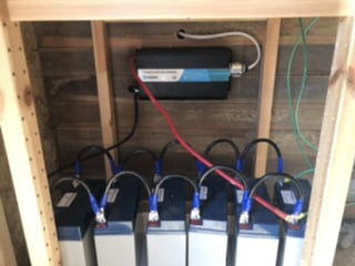
This is the type of battery I’m using. I have 6 wired in parallel. Using a volt meter everything seems to be fine until I hook up the solar panels. That’s when it seems the batteries and inverter are getting too much power and the system appears to be showing over voltage. When the panels are connected the batteries are reading almost 16 volts.

-
The 12 volt batteries are in parallel, as you said, and as the pictures show.
Still interested in the exact DC voltage measurements (Vpanel input, Vbatt output at the charger, Vbatt at the battery bank, etc.).
If the charge controller is working correctly, then disconnecting the solar panels, then disconnecting the battery cables (from the solar charger), wait 5 minutes, Then 1. reconnect the batteries. And 2. reconnect the solar panels--Give the controller a "clean boot" (gets battery voltage first to figure out if 12 or 24 volts, then connect solar panels).
What is the Vpanel input voltage from the Array (especially when the green "panel" LED is blinking)?
And what is the battery bank voltage when the AC inverter fails to start/run? Do you see the battery voltage start at ~12.x volts and rise to 14.4 volts (may take 10's of minutes to hours, depending on amount of sun and battery bank state of charge)? Do you see the battery voltage exceeding 15.0 volts when charging?
-BillNear San Francisco California: 3.5kWatt Grid Tied Solar power system+small backup genset -
Thanks bill. I’ll try that tomorrow when the sun comes out.BB. said:The 12 volt batteries are in parallel, as you said, and as the pictures show.
Still interested in the exact DC voltage measurements (Vpanel input, Vbatt output at the charger, Vbatt at the battery bank, etc.).
If the charge controller is working correctly, then disconnecting the solar panels, then disconnecting the battery cables (from the solar charger), wait 5 minutes, Then 1. reconnect the batteries. And 2. reconnect the solar panels--Give the controller a "clean boot" (gets battery voltage first to figure out if 12 or 24 volts, then connect solar panels).
What is the Vpanel input voltage from the Array (especially when the green "panel" LED is blinking)?
And what is the battery bank voltage when the AC inverter fails to start/run? Do you see the battery voltage start at ~12.x volts and rise to 14.4 volts (may take 10's of minutes to hours, depending on amount of sun and battery bank state of charge)? Do you see the battery voltage exceeding 15.0 volts when charging?
-Bill -
There is a possibility that the controller has failed, I once had a similar PWM controller that failed in a full power condition much like what is being described.1500W, 6× Schutten 250W Poly panels , Schneider MPPT 60 150 CC, Schneider SW 2524 inverter, 400Ah LFP 24V nominal battery with Battery Bodyguard BMS
Second system 1890W 3 × 300W No name brand poly, 3×330 Sunsolar Poly panels, Morningstar TS 60 PWM controller, no name 2000W inverter 400Ah LFP 24V nominal battery with Daly BMS, used for water pumping and day time air conditioning.
5Kw Yanmar clone single cylinder air cooled diesel generator for rare emergency charging and welding. -
davidnolen said: ok. Hopefully I can answer everything you are asking it’s roughly 46 degrees out.-batteries are measuring -12.68 volts (no load or panels)
-Leads off battery to inverter -12.68 volts (no load or panels)
-leads to charge controller - 12.7 volts (no load or panels) light is solid green
With the battery connected to inverter and with a light on, same measurement places are 12.3 volts
now the sun is out and a little warmer but not much.- solar panels seem to be putting out 21.7 volts
I re did the connecting process like you suggested and now the first 2 lights are solid green. After about 1 minute the second light started flashing green
- at the charger it’s measuring 16.5 volts for the solar panels
- at the battery connection on the charger it reads 14.4 volts
- at the inverter where the battery bank connects it reads 14.4 volts
I turned the inverter power on and the light connected to it and the middle light on the charge controller and after about a minute it went to sold green and stopped flashing. (Second light from left). However I’m not having the over charge issue in the inverter now.Any ideas?
Thanks bill. I’ll try that tomorrow when the sun comes out.BB. said:The 12 volt batteries are in parallel, as you said, and as the pictures show.
Still interested in the exact DC voltage measurements (Vpanel input, Vbatt output at the charger, Vbatt at the battery bank, etc.).
If the charge controller is working correctly, then disconnecting the solar panels, then disconnecting the battery cables (from the solar charger), wait 5 minutes, Then 1. reconnect the batteries. And 2. reconnect the solar panels--Give the controller a "clean boot" (gets battery voltage first to figure out if 12 or 24 volts, then connect solar panels).
What is the Vpanel input voltage from the Array (especially when the green "panel" LED is blinking)?
And what is the battery bank voltage when the AC inverter fails to start/run? Do you see the battery voltage start at ~12.x volts and rise to 14.4 volts (may take 10's of minutes to hours, depending on amount of sun and battery bank state of charge)? Do you see the battery voltage exceeding 15.0 volts when charging?
-Bill
-
Everything seems OK with the charge controller.
If you "rebooted" the charge controller (battery connection first, solar panels second)--It does behave correctly (charging at 14.4 volts)--It does seem that the controller was not booted properly before (solar panels first, then battery bank) and the controller may have been defaulting for a 24 volt battery bank...
Sealed batteries can be damaged by over charging--So you will have to keep an eye on them with a voltmeter when under load and see how they perform (do they go dead quickly, or support your loads as expected). If they were not overcharged too much--hopefully they are OK.
Since you are not using the "load control" on the charge controller (this is correct for your system--Wiring the inverter to the battery bank is correct because the controller load control does not supply enough current for the inverter)--You only "care" about the first two LEDs. From the manual on Page 2:
Panel Icon:
Green ON: Solar power is charging the battery
Green BLINKING: The system is over voltage
Battery Icon:
Green ON: Battery level is in the right range Green
SLOWLY FLASHING: Battery level is full Orange ON: Battery level is low
Red ON: Load cut-off (this is probably wrong--Check face of controller--"dead" battery?)
Orange ON: The load output is on (probably wrong--Battery low?)
Light Bulb Load:
Red SLOWLY FLASHING: Overload*
Red BLINKING: Load is short-circuit*
Table 2. LED indicators
The manual probably has some errors in it (above LED indicators)... Using the voltmeter will be the tool you use to confirm the condition of the battery bank and how well the charge controller is working.
At some point, you are going to need to replace the smaller batteries and use a full size, or several batteries in series/parallel for a larger bank (if you continue to use the AC inverter much and/or at higher power output).
When you are ready, please come back and we can help with your planning for the upgraded system.
Otherwise, if you stay with your present system size... Using 12 volt LEDs may be the next step and not using the inverter for day to day use... Also a single 12 volt battery in the 100-200 AH range, or a pair of 6 volt @ ~200 AH batteries (aka "Golf Cart" batteries) would be a better bank for your system than the smaller cells in parallel (unless your power needs stay very low).
-BillNear San Francisco California: 3.5kWatt Grid Tied Solar power system+small backup genset

Categories
- All Categories
- 233 Forum & Website
- 140 Solar Forum News and Announcements
- 1.3K Solar News, Reviews, & Product Announcements
- 181 Solar Information links & sources, event announcements
- 895 Solar Product Reviews & Opinions
- 252 Solar Skeptics, Hype, & Scams Corner
- 22.5K Solar Electric Power, Wind Power & Balance of System
- 3.5K General Solar Power Topics
- 6.7K Solar Beginners Corner
- 1K PV Installers Forum - NEC, Wiring, Installation
- 2.1K Advanced Solar Electric Technical Forum
- 5.6K Off Grid Solar & Battery Systems
- 428 Caravan, Recreational Vehicle, and Marine Power Systems
- 1.1K Grid Tie and Grid Interactive Systems
- 656 Solar Water Pumping
- 816 Wind Power Generation
- 621 Energy Use & Conservation
- 623 Discussion Forums/Café
- 316 In the Weeds--Member's Choice
- 74 Construction
- 125 New Battery Technologies
- 108 Old Battery Tech Discussions
- 3.8K Solar News - Automatic Feed
- 3.8K Solar Energy News RSS Feed