Design a solar tracker using two servo motors, a light sensor and an Arduino UNO board.
Bombala
Registered Users Posts: 1 ✭
In modern solar tracking systems, the solar panels are fixed on a structure that moves according to the position of the sun.
Today I want to introduce a project of designing a solar tracker using two servo motors, a light sensor consisting of four LDRs and Arduino UNO board.
First watch the video:
http://https//youtu.be/X0z3px5KgEs
LDRs sense the amount of sunlight falling on them. Four LDRs are divided into top, bottom, left and right.
For east – west tracking, the analog values from two top LDRs and two bottom LDRs are compared and if the top set of LDRs receive more light, the vertical servo will move in that direction.

Step 5

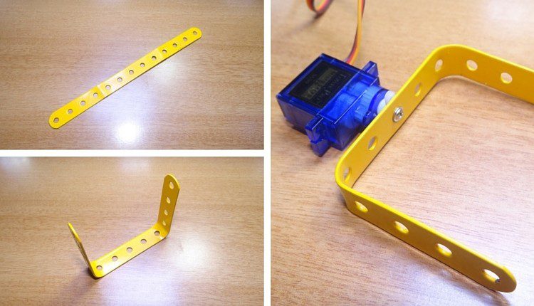
Today I want to introduce a project of designing a solar tracker using two servo motors, a light sensor consisting of four LDRs and Arduino UNO board.
First watch the video:
http://https//youtu.be/X0z3px5KgEs
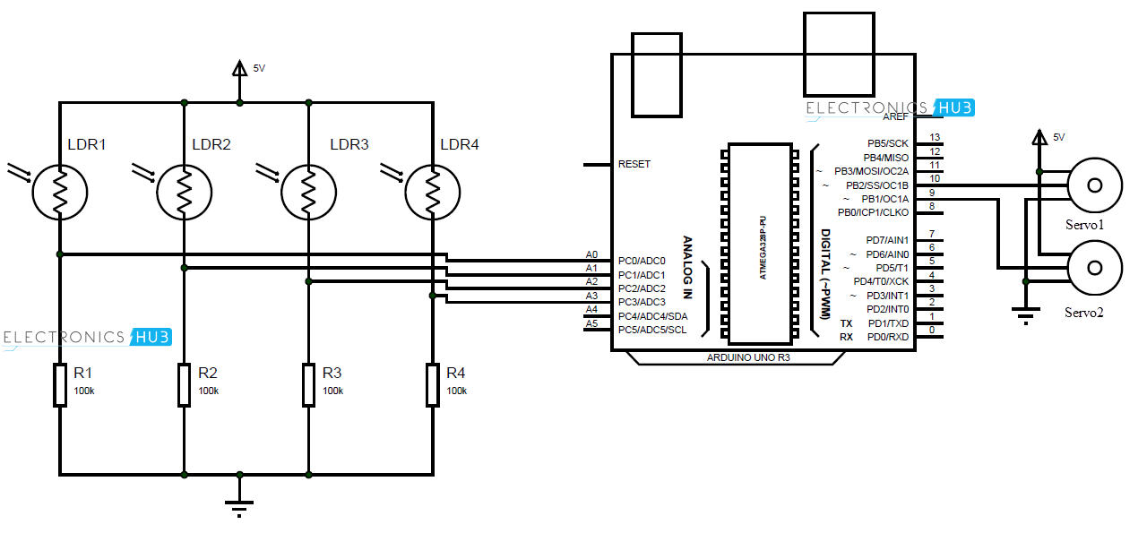
Circuit Diagram
The circuit design of solar tracker is simple but setting up the system must be done carefully.
Four LDRs and Four 100KΩ resistors are connected in a voltage divider fashion and the output is given to 4 Analog input pins of Arduino.
The PWM inputs of two servos are given from digital pins 9 and 10 of Arduino.
Working
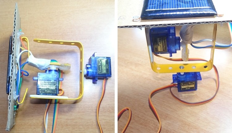
LDRs are used as the main light sensors. Two servo motors are fixed to the structure that holds the solar panel. The program for Arduino is uploaded to the microcontroller. The working of the project is as follows.
For east – west tracking, the analog values from two top LDRs and two bottom LDRs are compared and if the top set of LDRs receive more light, the vertical servo will move in that direction.
If the bottom LDRs receive more light, the servo moves in that direction.
For angular deflection of the solar panel, the analog values from two left LDRs and two right LDRs are compared. If the left set of LDRs receive more light than the right set, the horizontal servo will move in that direction.
If the right set of LDRs receive more light, the servo moves in that direction.
Setup
Step-1
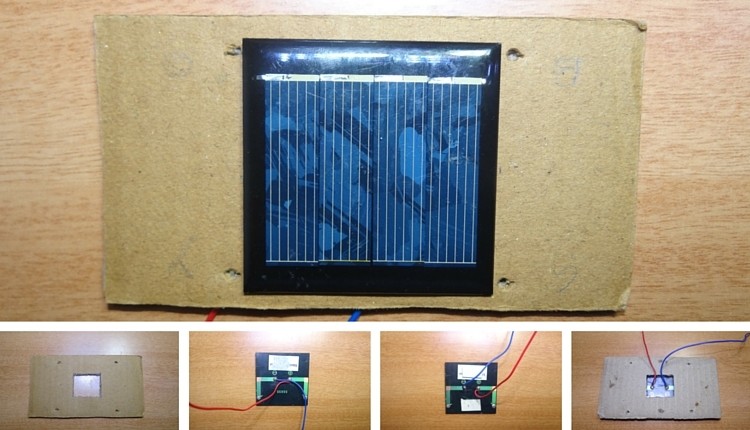
- Take cardboard. Make a hole in the middle and four holes on four sides so that LDR fit into that.
- Stick the solar panel to the cardboard and bring two wires of the panel out as shown.

Step 2
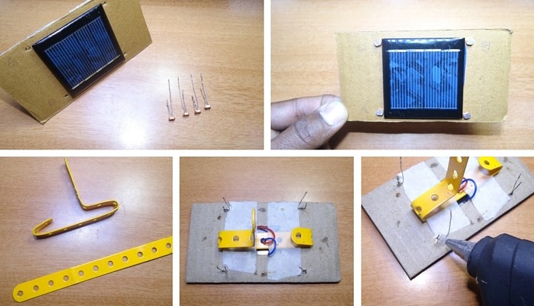
- Now cut one of the two leads of the LDR so that one lead is shorter and other is longer.
- Insert these four LDRs into four holes as shown.
- Bend the straight Perforated metal strip as shown below.
- Place the bent metal strip on the back side of the cardboard
- Apply glue to the LDR to fix them firmly.

Step 3
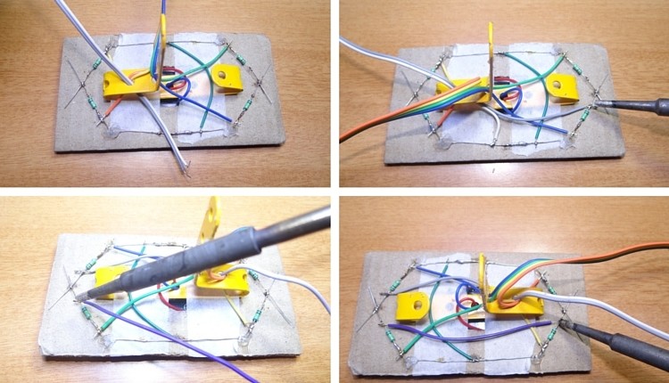
- Solder the two leads of LDR as shown
- To the other ends of LDR Solder resistors of 10k ohm
- Join the four leads of the 4 LDRs by connecting with a wire.

Step4
- Now take a bus wire.This is used to connect the Outputs of four LDRs to Arduino board.
- Insert it into metal strip as shown in the image.
- Now Solder the four wires to four LDRs at any point between LDR and resistor.

Step 5
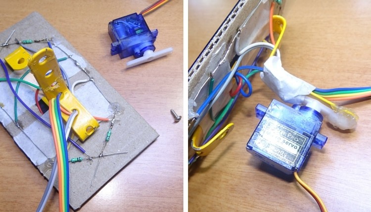
- Insert another two wire bus into the perforated metal strip as shown.This is used for supplying Vcc and GND to LDR circuit.
- Solder one wire to the leads of LDRs which are connected to resistors and other wire to the other leads.
- Short the leads of LDRs connected to resistors using a wire as shown.

Step 6
- Now connect a servo motor to the Perforated metal strip using Screw.
- Apply glue to the servo to fix it firmly.

Step 7
- Take another straight Perforated metal strip and bend it as shown in the figure.

Step 8
- Now place the set up of solar panel and first servo motor to the metal strip of second servo motor as shown.

Project Code
#include <Servo.h>
//defining Servos
Servo servohori;
int servoh = 0;
int servohLimitHigh = 160;
int servohLimitLow = 20;

Servo servoverti;
int servov = 0;
int servovLimitHigh = 160;
int servovLimitLow = 20;
//Assigning LDRs
int ldrtopl = 2; //top left LDR green
int ldrtopr = 1; //top right LDR yellow
int ldrbotl = 3; // bottom left LDR blue
int ldrbotr = 0; // bottom right LDR orange

 void setup ()
 {
  servohori.attach(10);
  servohori.write(0);
  servoverti.attach(9);
  servoverti.write(0);
  delay(500);
 }

void loop()
{
  servoh = servohori.read();
  servov = servoverti.read();
  //capturing analog values of each LDR
  int topl = analogRead(ldrtopl);
  int topr = analogRead(ldrtopr);
  int botl = analogRead(ldrbotl);
  int botr = analogRead(ldrbotr);
  // calculating average
  int avgtop = (topl + topr) / 2; //average of top LDRs
  int avgbot = (botl + botr) / 2; //average of bottom LDRs
  int avgleft = (topl + botl) / 2; //average of left LDRs
  int avgright = (topr + botr) / 2; //average of right LDRs

  if (avgtop < avgbot)
  {
    servoverti.write(servov +1);
    if (servov > servovLimitHigh)
     {
      servov = servovLimitHigh;
     }
    delay(10);
  }
  else if (avgbot < avgtop)
  {
    servoverti.write(servov -1);
    if (servov < servovLimitLow)
  {
    servov = servovLimitLow;
  }
    delay(10);
  }
  else
  {
    servoverti.write(servov);
  }

  if (avgleft > avgright)
  {
    servohori.write(servoh +1);
    if (servoh > servohLimitHigh)
    {
    servoh = servohLimitHigh;
    }
    delay(10);
  }
  else if (avgright > avgleft)
  {
    servohori.write(servoh -1);
    if (servoh < servohLimitLow)
     {
     servoh = servohLimitLow;
     }
    delay(10);
  }
  else
  {
    servohori.write(servoh);
  }
  delay(50);
<span>}
</span>
Here is the end of this project. I also take some reference from one blog article, which is talking about an almost complete introduction to solar cells: http://www.apogeeweb.net/article/27.html . Read it if you need it. Thanks for reading!Comments
-
Doing this with 2 to 5 KW of solar is where the pedal meets the road. A nice project you have. Good job!"we go where power lines don't" Sierra Nevada mountain area
htps://offgridsolar1.com/
E-mail offgridsolar@sti.net -
There is no need to adjust more than every 20-45 minutes. Put it to sleep or wait for that time. Adjusting all the time just eats up power.
-
Im new to this. Does the code need to be input to the arduino, if so please explain. Thanks
-
Also what value are the ldrs?
-
Yes, you need the Arduino IDE to do that.hangfireal said:Im new to this. Does the code need to be input to the arduino, if so please explain. Thanks -
There is the Arduino hardware... And there is the Arduino development environment.
https://www.arduino.cc/en/Main/Software
You write code in the IDE:
https://en.wikipedia.org/wiki/Integrated_development_environment (generic information on what IDE is)
and plugin your Arduino and upload the code into code memory, and run it on the Arduino. You can write in "C" like code (as I remember), compile it, download it, and debug it.
Other than buying the hardware (not expensive), the IDE is free to download.
-Bill
Near San Francisco California: 3.5kWatt Grid Tied Solar power system+small backup genset -
I once designed and built a heliostat (similar but with a mirror). Instead of sensors, I positioned based on date/time of day and calculating all the angles. Not clear that this is better/worse, but with sensors, I could imagine excessive or inefficient movement on a day with intermittent clouds.
I am available for custom hardware/firmware development
-
It is worth noting that you don't really have to be exact. You can be 18 degrees off and only lose 5% of the energy. You can be 8 degrees off and lose only 1%. You can step it once an hour, come within 5 degrees and be essentially as good as a continuous perfect adjustment.jonr said:I once designed and built a heliostat (similar but with a mirror). Instead of sensors, I positioned based on date/time of day and calculating all the angles. Not clear that this is better/worse, but with sensors, I could imagine excessive or inefficient movement on a day with intermittent clouds. -
If I was doing it, that's (~hourly) what I'd do, and maybe test for a low limit light threshhold (so a headlight or whatever hitting it at night wouldn't make it go).Off-grid.
Main system ~4kw panels into 2xMNClassic150 370ah 48v bank 2xOutback 3548 inverter 120v + 240v autotransformer
Night system ~1kw panels into 1xMNClassic150 700ah 12v bank morningstar 300w inverter -
Very good algorithms abound to do this with a minimal amount of code and you can save the hardware to create the different voltages.
http://ascend4.org/Calculation_of_sun_position
Really a simple X amount of time, time of year, type table lookup should suffice for single degree accuracy. -
Even simpler with a photocell like Wattsun uses. No computer and 3 operating correctly here since 2005. Many out in the world with my fingerprints on them also. The design work is mature and no worries about headlights.
 Built for 3 to 4 KW of solar @ 100MPH. Many still turning in hurricane zones also.
You do have to give them a squirt of grease from a grease gun once a year....."we go where power lines don't" Sierra Nevada mountain area
htps://offgridsolar1.com/
E-mail offgridsolar@sti.net
Categories
- All Categories
- 233 Forum & Website
- 141 Solar Forum News and Announcements
- 1.4K Solar News, Reviews, & Product Announcements
- 200 Solar Information links & sources, event announcements
- 900 Solar Product Reviews & Opinions
- 256 Solar Skeptics, Hype, & Scams Corner
- 22.5K Solar Electric Power, Wind Power & Balance of System
- 3.5K General Solar Power Topics
- 6.7K Solar Beginners Corner
- 1K PV Installers Forum - NEC, Wiring, Installation
- 2.1K Advanced Solar Electric Technical Forum
- 5.6K Off Grid Solar & Battery Systems
- 430 Caravan, Recreational Vehicle, and Marine Power Systems
- 1.1K Grid Tie and Grid Interactive Systems
- 656 Solar Water Pumping
- 817 Wind Power Generation
- 624 Energy Use & Conservation
- 624 Discussion Forums/Café
- 316 In the Weeds--Member's Choice
- 75 Construction
- 125 New Battery Technologies
- 108 Old Battery Tech Discussions
- 3.8K Solar News - Automatic Feed
- 3.8K Solar Energy News RSS Feed


