need some insight on a problem
It keeps giving me a fault F63 ...AC overload when it does this it trips the 175 amp DC breaker. The only way to get this thing back going is to reset the breaker, disable the inverter, go back to the SCP and start the generator manually. Once the generator is running, the inverter qualifies the AC and the power comes on, inverter still disabled doing AC pass through, the SCP reports that the DC is -290-300 amps.
I can enable the inverter at this time, but the Dc is still -290-300 amp.....I dont believe it is really drawing that because the voltage stays above 50 or whatever it was to begin with, so it isnt pulling the batteries down.
after the generator has been running a while, the DC will go normal 75 amp...at this point I can shut the generator off and the inverter works fine
it usually does this when it rains a lot or it get real cold...the inverter is in a shed...cant get rained on
I have had this apart once after it started doing this....I did not see any relays where the coil is, but I am sure that is where the noise is coming from
If anyone else might know what the problem is....please.....this may be a BoB/Robin kinda question
Comments
-
Don't know that inverter, but I'm kinda wondering if there's a problem with the transfer switch. Rain/cold may mean high humidity and an intermittent short fault?Off-grid.
Main system ~4kw panels into 2xMNClassic150 370ah 48v bank 2xOutback 3548 inverter 120v + 240v autotransformer
Night system ~1kw panels into 1xMNClassic150 700ah 12v bank morningstar 300w inverter -
The XW's have a couple or 3 transfer relays in them, and early ones used to weld contacts closed. But those don't fix themselves easily. So something else is happening to it. I've not gotten into the innards of mine.
Have you tried re-wiring to the other AC input ? AC 1 is usually Grid, AC 2 generator. Perhaps Dave A can offer a suggestionPowerfab top of pole PV mount | Listeroid 6/1 w/st5 gen head | XW6048 inverter/chgr | Iota 48V/15A charger | Morningstar 60A MPPT | 48V, 800A NiFe Battery (in series)| 15, Evergreen 205w "12V" PV array on pole | Midnight ePanel | Grundfos 10 SO5-9 with 3 wire Franklin Electric motor (1/2hp 240V 1ph ) on a timer for 3 hr noontime run - Runs off PV ||
|| Midnight Classic 200 | 10, Evergreen 200w in a 160VOC array ||
|| VEC1093 12V Charger | Maha C401 aa/aaa Charger | SureSine | Sunsaver MPPT 15A
solar: http://tinyurl.com/LMR-Solar
gen: http://tinyurl.com/LMR-Lister , -
Sounds like welded contacts, usually from grid surges, genset surges and lack of SPD's. Are there any warnings beside the fault?
It is out of support now but you may be able to get the AC1/Ac2 transfer switches. Contact support by filling out the form and see what they say.
It also could be the power bridge PCB and that one is the end of the road for the unit unless you find a component level repair shop. If you go that route please post who you find. A CSW 4048 would be a good spare but it does not have the charge current of the XW.
Good Luck"we go where power lines don't" Sierra Nevada mountain area
htps://offgridsolar1.com/
E-mail offgridsolar@sti.net -
I was thinking the PCB Dave, but still dont know of a relay where the coil is that would make that sound...and I'm sure the sound is coming from there. also thought maybe one of the coils may have a intermittent short somewhere
there is a repair place in White House, TN....thats where I took it when the network PCB went bad, cost me $700 to have them fix it, even though I knew what was wrong with it, I couldnt get the part....schneider wouldnt sell it to me. So I can imagine what it would cost to fix an intermittent problem no to mention how long I would be without power till it was fixed
Those guys at White House do a lot of RV's and boats...their tech is tops.... the only place I could find within 150 miles to fix it ( they were 40 miles from me)
I was thinking about getting a new CSW and using the XW as a vehicle demo and portable power for a construction work truck....the technology in those compared to the old rock solid SW, has improved tremendously ( still wouldnt mind having my old SWs back ).... the problem with the old ones is you had to have 2 to have 120/240 or use an auto transformer with one which left you with less amps,and a sync cable, some of the older SWs you even had to get a grid tie box, the new ones you only need one, but mine worked great, it's just the local utility didnt like them....one of them was a little slow shutting the power off all the way, something of a capacitor effect, so I sold those to a guy in Tehachapi California for a new off grid home....I suppose he is still using them, that was in 2008
I have since went off grid and am unable to get reconnected due to changes in the rules for connecting to the grid in kentucky...they want people to have a 1 million dollar liability policy....theres more to that story.... but I am unwilling to pay more just to connect to the grid....the inverters are UL listed just like any appliance and if connected correctly cannot do any damage to the grid....especially with just 2000 watts
I was the person that got the local utility into residential grid tie solar, along with TN Andy who is also a member here.... I had to have a sit down with tri county and TVA to hash out residential grid tie in this area because no one else was doing it except government entities like schools
any who.....the inverter is up and running again till it happens again and hasnt offered to fault again since I wrote this, ...if/when I do get a CSW I was gonna tear the XW down in more detail ....when I do, I will post my findings
it's just odd that the inverter reports -290 amps but isnt really happening, maybe problem in firmware
TTFN
12 panels 6 series 2 parallel 2100 watts, 1 XW60-150 CC, 16 trojan 6V batteries 8 series 2 parallel 450 Ah, 1 XW 6848 pro, 1 5500 watt champion inverter generator( I know...I need a 12Kw ) -
You could try reset to factory, but if something is tripping the 175A breaker, there is a real problem. No warnings right? Sometimes before the fault a warning is logged and it can guide you.
The sound location can fool you also as it could be reflecting. When you do failure analysis you have to keep an open mind.
The transfer switches are in the left side and the power bridge is in the right.
Thanks for the info on White house. I have a few that I removed from a site that need lightning repair. A bit far for me but nice to know.
Might just sell them for parts."we go where power lines don't" Sierra Nevada mountain area
htps://offgridsolar1.com/
E-mail offgridsolar@sti.net -
Did you do what Mike suggested a few posts back?"we go where power lines don't" Sierra Nevada mountain area
htps://offgridsolar1.com/
E-mail offgridsolar@sti.net -
I did....I can can remove all the wiring while is off and turn it back on..bam...f63Dave Angelini said:Did you do what Mike suggested a few posts back?
I also put the generator on ac1 for a bit, of course it wont work/place nice with a generator and AGS...also the batteries wont charge unless you enable grid support
1 other thing I just did before it got dark...I remembered it didnt start doing this till I put new cat5 cable on the system.....seems the new puppy I left in the house chewed on the old one......anyways
I cut both ends off the new cable and measured it....126 feet,....now I do regular network stuff with computer and routers, cat 5 starts losing signal after 100 feet
I'm not sure of the effects it has on canbus/xanbus network, but it may have caused it to corrupt the actual data somehow...so I have cut the cable down to under 100 feet and once again got the inverter to straighten out....I will see what happens when I turn the generator off this time as it is raining and the temperature outside is 40-50 degrees
by the by dave...you stll have that xw4024 for sale...if so send me a pm on the price
12 panels 6 series 2 parallel 2100 watts, 1 XW60-150 CC, 16 trojan 6V batteries 8 series 2 parallel 450 Ah, 1 XW 6848 pro, 1 5500 watt champion inverter generator( I know...I need a 12Kw ) -
Xanbus max length 130 feet. A network cable (cat5) is over 300 feet but it does depend on good devices and what the network consists of
Sorry the 4024 is gone. I have a couple 6048's that were hit and they did not smell very nice when I took them off the wall, with help")
A bunch of other spares but they are for my local clients and I really am not into shipping so count me out.
Below is the new gateway for Schneider systems out next month, maybe. You can hook up a network and monitor and control from anywhere without port forwarding from your ISP. I don't know how they got the extra resolution for voltage as they said before it was impossible. .
.
"we go where power lines don't" Sierra Nevada mountain area
htps://offgridsolar1.com/
E-mail offgridsolar@sti.net -
well, the network cable wasnt the problem...I was right in the middle of shoving a spoonful of soup in my mouth and ern ern ern...power goes out again
well I just got done tearing the inverter apart.....still nothing to indicate why it only does it when its cold or wet....or so I thought
this time I took the huge coil off ( couldve used some help) ( dave ) and the transformer off. As I was putting the cover back over that part, I noticed a small what looked to be scorch mark, so I inspectedthe cable that was on that side, sure enough it had a flat spot as if it was rubbing on the casing. Now I know electricity is a frequency vibration and maybe ...just maybe over a period of 10 years this cable had worn just enough of a spot to go through the sheilding....and every now and then with humidity and cold weather, the electric would arc through or touch the casing causing the cable to jump ....possibly what I was hearing that sounded like relay chattering
now finally all back together, I crossed my fingers and flipped the breaker....f63....reset...breaker trips
I remained calm......flipped the breaker again....the smooth sound of a sinusoidal oscillation coming from the inverter and a 0.24 on the display....meaning my refrigerator was probably on
its still raining and it getting colder and the inv.....nope aint gonna jinks myselfI took pictures...I will post them after I eat
12 panels 6 series 2 parallel 2100 watts, 1 XW60-150 CC, 16 trojan 6V batteries 8 series 2 parallel 450 Ah, 1 XW 6848 pro, 1 5500 watt champion inverter generator( I know...I need a 12Kw ) -
Cool. Lots of problems are fixed by close inspection and looking for anything unusual.
")
Of course, many things taken apart, never work again.
-BillNear San Francisco California: 3.5kWatt Grid Tied Solar power system+small backup genset -
okay...here are some pics....if you ever wanted to know what the inside of an XW4548 looks like


the AC out also has ac1 in from grid and ac2 in from generator, the logic board is where the firmware is that tells all the other boards what to do
I think this is the 240v transformer
could have used some help lifting this out....this is why inverters are so heavy....this is where the magic happens could be the cause of my anguish, wont know for a few days, but I think the black 2/0 cable was rubbing on it as that transformer vibrated......I hope Schneiderfixed that design flaw
so here is my band-aid fix...cant touch the metal now
should the f63 happen again, I will disconnect the chassis ground and see if it still does it....but for now.......crossed fingers
12 panels 6 series 2 parallel 2100 watts, 1 XW60-150 CC, 16 trojan 6V batteries 8 series 2 parallel 450 Ah, 1 XW 6848 pro, 1 5500 watt champion inverter generator( I know...I need a 12Kw ) -
Wow ! Did you happen to notice or get a pic of the capacitors on the DC board ? I'm wondering what the VDC rating is on them ?Powerfab top of pole PV mount | Listeroid 6/1 w/st5 gen head | XW6048 inverter/chgr | Iota 48V/15A charger | Morningstar 60A MPPT | 48V, 800A NiFe Battery (in series)| 15, Evergreen 205w "12V" PV array on pole | Midnight ePanel | Grundfos 10 SO5-9 with 3 wire Franklin Electric motor (1/2hp 240V 1ph ) on a timer for 3 hr noontime run - Runs off PV ||
|| Midnight Classic 200 | 10, Evergreen 200w in a 160VOC array ||
|| VEC1093 12V Charger | Maha C401 aa/aaa Charger | SureSine | Sunsaver MPPT 15A
solar: http://tinyurl.com/LMR-Solar
gen: http://tinyurl.com/LMR-Lister , -

12 panels 6 series 2 parallel 2100 watts, 1 XW60-150 CC, 16 trojan 6V batteries 8 series 2 parallel 450 Ah, 1 XW 6848 pro, 1 5500 watt champion inverter generator( I know...I need a 12Kw ) -

Above Photo. Here is a pic of one of my 8kW Inverters being assembled with the major parts just gone in and not connected up yet. The Toroid is about 108lbs / 48kgs,. I do a single primary cable 75mm/2 on the outside of the toroid as it enables better toroid cooling.
t00ls, Very nice pictures.
Mods, I am never sure if my comments are helpful or not, so if I get a bit ambitious or you feel I am not helping please do say so, I wont be offended, honest!.. My Mrs reckons that folk ask me questions and i answer them "but after a while there eyes Glaze over. !!!
I have never examined one of those XW 4548 inverters, but the caps and the amount of caps is very interesting.
I only use 6off 100v 10000uf electrolytic (can) capacitors at 35mm dia x 60mm to 80mm long.
Toroid transformers can be an issue if they are constantly running at max temperature and vibrations will eventually cause failure on the secondary windings, or the primary windings if they are multicable wound.
We wind our own Toroid, as we can get a better insulated and more hard working Toroid than a commercial winding machine.
The insulation on the visible cables is normally sufficient, however there are a few tips for those big cables...... use good quality plastic cable ties around the cable where it gets close or touches a possible source for shorting out..... ensure that the centre holding bolt on the toroid, that bolt that you see does not touch any metal as that bolt then becomes one turn of your Primary, ie its big splat time!
If you still have issues, try checking each of the Secondary and primary windings, they should be individually isolated. The secondary's are probably split for 120v so there may be a floating neutral on them.
I think that the Pic of what you say is a AC transformer is in fact a Choke, but then I have never really got inside a 4548.
Everything is possible, just give me Time.
The OzInverter man. Normandy France.
3off Hugh P's 3.7m dia wind turbines, (12 years running). ... 5kW PV on 3 Trackers, (8 years) .... 14kW PV AC coupled using Used/second hand GTI's, on my OzInverter created Grid, and back charging with the AC Coupling and OzInverter to my 48v 1300ah batteries.
-
and that about the extent of my knowledge on these....I'm really not the smartclockmanfran said:one of my 8kW Inverters being assembled with the major parts just gone in and not connected up yet.__________________________________________________________________________________
you're saying you build inverters?
_________________________________________________________________________________t00ls, Very nice pictures.
______________________________________________________________________________
thanks
____________________________________________________________________________My Mrs reckons that folk ask me questions and i answer them "but after a while there eyes Glaze over. !!!
---------------------------------------------------------------------------------------------------------------------------------------
thats what happens when I start talking to people.......you really can see it when you start saying stuff and their minds start getting confused and haven't a clue what you are saying...that glaze in the eyes
--------------------------------------------------------------------------------------------------------------------------------------I think that the Pic of what you say is a AC transformer is in fact a Choke, but then I have never really got inside a 4548.
------------------------------------------------------------------------------------------------------------------------------------------
what I know: DC + comes in on the left connection and goes out to the torroid on the right connection

the left connection should be the DC + side that connects to the thing in the previous picture, it goes through the black and red square thing which should be an amp meter
the right side goes to the torroid
these wires come off of the torroid
from top to bottom: top connector block X1 to L1, X2 to N, lower connector block X3 to N, X4 to L2
what I dont understand: how are they able to get 60A from those small wires, and N is usually a white wire yet the top connector has them reversed
what I know about this picture: you can rearrange these connections to get 120V single phase...120/240 split phase.....or make it one of three 3 phase voltages
12 panels 6 series 2 parallel 2100 watts, 1 XW60-150 CC, 16 trojan 6V batteries 8 series 2 parallel 450 Ah, 1 XW 6848 pro, 1 5500 watt champion inverter generator( I know...I need a 12Kw ) -
@clockmanfran
I just read a post in the backshed where you explain the toroid coil.....would love to read your book
12 panels 6 series 2 parallel 2100 watts, 1 XW60-150 CC, 16 trojan 6V batteries 8 series 2 parallel 450 Ah, 1 XW 6848 pro, 1 5500 watt champion inverter generator( I know...I need a 12Kw ) -
 I trust the above helps... this is the basic layout for a H bridge 6kW Inverter that uses a toroid.
For 60a at 120vac then the secondary could be 1.8mm diameter x 6off, ie 6 windings of the same number of turns with the 6 joining together at the start and finish of the windings. Although I suspect the commercial manufacturers have only used 4.
Yes, that definitely looks like a ribbon wound choke as its on the Primary winding cable, and the output is split into about 6off cables and should be heading for the heatsink and Power FET's gates.
On my previous above photo I use a large Ferrite choke that is doubled up and have a minimum of 3 complete coils wrapped around the centre arm of the ferrite core. This reduces the idle power wattage of the Inverter in standby use. In essence its reducing the switching Frequency and other parasitic by going super saturated.
I know folk that have spent a lot of time tuning the chokes to match their particular Power Board. With our/my power board we have found a sweet spot without the necessity of other tuning systems and added circuitry complications.
At this very moment I am doing a 2nd edition of the OzInverter book, "How to make your own 6kW PSW 48vdc to 50Hz 230vac Inverter" I am also adding a section, showing a few simple modifications on our control board required for 60Hz, and 120vac output modifications with a centre windings tap on the toroid secondary's.
"and that about the extent of my knowledge on these....I'm really not the smart"
I find that its amazing what you can learn when its necessary to do so.
Me ,? I am just a fool, its folk like 'Oztules' that can really push stuff. In 2015 We both wanted a good simple, robust and yet powerful cost effective inverter. Lots of blind alleys and lots of differing testing, but in the end we have a winner mostly with thanks to 'Oztules' willing to push stuff and blow it up. I was always playing catch up and being simplistic so others would understand.
Everything is possible, just give me Time.
The OzInverter man. Normandy France.
3off Hugh P's 3.7m dia wind turbines, (12 years running). ... 5kW PV on 3 Trackers, (8 years) .... 14kW PV AC coupled using Used/second hand GTI's, on my OzInverter created Grid, and back charging with the AC Coupling and OzInverter to my 48v 1300ah batteries.
-
Good Luck and as they say cross your fingers. I hope Bill is wrong but I know, he could be right....t00ls said:well, the network cable wasnt the problem...I was right in the middle of shoving a spoonful of soup in my mouth and ern ern ern...power goes out again
well I just got done tearing the inverter apart.....still nothing to indicate why it only does it when its cold or wet....or so I thought
this time I took the huge coil off ( couldve used some help) ( dave ) and the transformer off. As I was putting the cover back over that part, I noticed a small what looked to be scorch mark, so I inspectedthe cable that was on that side, sure enough it had a flat spot as if it was rubbing on the casing. Now I know electricity is a frequency vibration and maybe ...just maybe over a period of 10 years this cable had worn just enough of a spot to go through the sheilding....and every now and then with humidity and cold weather, the electric would arc through or touch the casing causing the cable to jump ....possibly what I was hearing that sounded like relay chattering
now finally all back together, I crossed my fingers and flipped the breaker....f63....reset...breaker trips
I remained calm......flipped the breaker again....the smooth sound of a sinusoidal oscillation coming from the inverter and a 0.24 on the display....meaning my refrigerator was probably on
its still raining and it getting colder and the inv.....nope aint gonna jinks myselfI took pictures...I will post them after I eat
I forgot to add that the network length thing has one more option with the new gateway. You can xanbus or ethernet to it along with wifi, the new part which can easily go farther than the cables.
All of those XW PCB's are obsolete now and only found in the repair from used units. The XW + will go that way down the road when the XW pro replaces it.
Having seen and done field repair (replace boards) each model is getting better. The caps that Mike asked for a pix are no longer there on the XW+. The XW Pro has higher voltage ratings for the MOSFETS and so Schneider should be able do different things with output power down the road. After all the XW is DSP based and can be tweaked with firmware.
Xantrex was funded by DOD and I remember when they announced it on their old Forum Jeff Everett told Bob Gungel who was at Outback I think, the XW name means, Xantrex wins. "we go where power lines don't" Sierra Nevada mountain area
htps://offgridsolar1.com/
E-mail offgridsolar@sti.net -
the military mostly used trace SW inverters in the 80s...when xantrex took over trace...the contract was still there
fast forward 2010 ....in the MRAP is a xantrex prosine 2000 watt inverter for ac electonics, the reason I know is because I drove them in Iraq
Bob has had an interesting career ....trace, xantrex, co-founder of outback, and now midnite solar....he has advanced inverter and charge controller technology to where it is today
thanks bob
and yes...most times when I tear stuff apart and just put it back together, it doesnt function....over time I have realized what how far I can take things apart before it wont work
this was one of those times
for now...the old XW is working in high humidity and the temp is at 50 or so degrees...my bandaid is working I think
12 panels 6 series 2 parallel 2100 watts, 1 XW60-150 CC, 16 trojan 6V batteries 8 series 2 parallel 450 Ah, 1 XW 6848 pro, 1 5500 watt champion inverter generator( I know...I need a 12Kw ) -
@clockmanfran
On my previous above photo I use a large Ferrite choke that is doubled up and have a minimum of 3 complete coils wrapped around the centre arm of the ferrite core.-----------------------------------------------------------------------------------------------------------------------------------------------I saw that, but what does a choke do and which is better, ribbon wound or ferrite12 panels 6 series 2 parallel 2100 watts, 1 XW60-150 CC, 16 trojan 6V batteries 8 series 2 parallel 450 Ah, 1 XW 6848 pro, 1 5500 watt champion inverter generator( I know...I need a 12Kw ) -
How is the Kentucky rain doing? " "Kentucky Rain" didn't make the cut for either album, but was added to the 2000 re-release of From Elvis In Memphis."
I attached a block of XW+ not too different than your model. I also did not think the burn mark was your problem as it would have been worse. I think your power bridge is toast and breaking down. "we go where power lines don't" Sierra Nevada mountain area
htps://offgridsolar1.com/
E-mail offgridsolar@sti.net -
I saw that, but what does a choke do and which is better, ribbon wound or ferrite.
I have answered briefly in my above post....
But here is 'Warpspeed's comments our professor on toroid's and the like. His wonderful explanation is far better than I could ever write.
'Warpspeed' has kindly allowed his comments to be published in my 2nd edition, but here is a brief extract..........
Ferrite choke, Warpspeed comments. May18
The choke is there to turn the high frequency PWM into a low frequency 50Hz sine wave.
It does that by storing and releasing energy to average out the fast and very violent on/off high frequency PWM square wave switching, and turn it into a nice slowly varying sine wave with very limited high frequency ripple current.
Rather like the springs on your car. The wheel can bounce up and down fairly fast with ripples in the road, but that is not transferred to the body. The springs store and release high frequency energy, and isolate the body from the nasty high frequency shocks and vibrations.
De we need a choke at all?
Do we need springs on a vehicle?
If we couple our mosfet bridge straight into a large transformer (that also typically has a very low self resonant frequency) the transformer will look like a big capacitor to any frequencies above the self resonant frequency. It all becomes vastly worse if the transformer also has a high voltage step up ratio.
Every time the mosfet bridge switches, it has to almost instantly charge or discharge the very high capacitance of the transformer secondary winding.
That causes massive short peak surges of currents in the bridge mosfets every time it switches.
Imagine the stress in the suspension of your car with solid steel wheels and no springs.
If our transformer step up ratio is 9:1 the distributed capacitance of the secondary appears 81 times larger in the primary than it really is in the secondary. And we have either a full charge or a discharge occurring twice every 23.5Khz cycle.
Everything runs hot, and the idling current will be higher than it should be.
We desperately need to fit a series choke to effectively isolate the transformer at 23.5 Khz, but allow through all the 50Hz energy with negligible loss.
There are some other bad effects of having no choke, quite apart from the extreme transformer capacitance loading problem at the switching frequency.
With no choke, the transformer primary sees raw PWM at 23.5Khz, and that produces something called skin effect in the wire. Current only flows on the outer most surface of the primary. The main bulk of the wire sees almost no current below a depth of only about 1 to 2mm. So the primary runs hot, ESPECIALLY at very high power, not so much at idling power.
That skin effect can be mitigated by using a large bunch of individual wires in the primary no bigger than about 2mm diameter, instead of one solid stranded cable, but that is only a band aid solution to the real underlying problem. A series choke solves that underlying problem at the source.
The laminated steel in the transformer core will also see circulating eddy currents at 23.5Khz, so the core runs hotter than it should.
Its all very bad, but an inverter without a choke will certainly appear to run and work fine.
But it will run hot and always be much more highly stressed for no useful purpose.
A small ferrite choke will work, but only at low power. If you are really serious about high power, fit a non saturating choke and your transformer will run slightly cooler, and your mosfets will run at lower peak currents.
continued.........
Everything is possible, just give me Time.
The OzInverter man. Normandy France.
3off Hugh P's 3.7m dia wind turbines, (12 years running). ... 5kW PV on 3 Trackers, (8 years) .... 14kW PV AC coupled using Used/second hand GTI's, on my OzInverter created Grid, and back charging with the AC Coupling and OzInverter to my 48v 1300ah batteries.
-
Ferrite choke, Warpspeed comments. May18, continued..............
Can a choke be made too large ?
Not really, but a very large choke can introduce indirectly some other effects.
The choke effectively decouples the bridge from the transformer at 23.5Khz, which is what we want. But as we make the choke increasingly larger, the decoupling effect also gets larger, and starts to have some effect at the lower frequencies.
If we have the usual expected transformer self resonance in the low Khz range, that can be excited and introduce stationary wobbles and faint ripples into the output, especially at very light loads. This can be especially noticeable where sometimes there is a kink just after the zero crossings when using unipolar PWM.
The high frequency wobbles should go away with heavier inverter loading, but the zero crossing kink may remain.
The kink should go away completely and the wobbles much less with bipolar PWM drive. The reason being that with bipolar drive there should be very low harmonic energy at multiples of 50Hz to excite transformer resonance.
Unipolar drive switches one side of the transformer hard at 50Hz, and that square wave will have odd harmonics that may tickle the transformer into wobbling or kink action.
Its not the choke causing all the wobbles, although a larger choke will probably make the wobbles worse, but the transformer resonances.
We can overcome that paradoxically by lowering the transformer resonant frequency with some shunt capacitance.
A suitably large choke allows us to do that.
With no choke, any extra added shunt capacitance would probably be death to our mosfet bridge from huge current spikes.
But with a non saturating choke, and suitable capacitance across the transformer we can design everything to have a pretty good overall result.
All the high voltage grid tie inverters use a non saturating steel cored choke in the primary, plus a capacitor of several uF across the primary to lower the transformer resonance and further attenuate any residual 23.5Khz ripple.
That is just not practical for a low dc voltage off grid inverter transformer. The capacitor across the primary would need to be very large and have an impossibly high ripple current rating. So we place the shunt capacitor across the 230v secondary where it can have 81 times less capacitance (with a 9:1 transformer ratio) but still work pretty much the same as if it were a much larger capacitor placed in the primary.
There is no magic in any of this, it just requires a slightly deeper understanding of what is really going on.
At very low power levels you can get away with far more design "sins".
One you get up into the multi kilowatt region, it all becomes a lot more important if you wish to build an efficient and reliable inverter.
I trust that helps clarifies a few things.........?
Everything is possible, just give me Time.
The OzInverter man. Normandy France.
3off Hugh P's 3.7m dia wind turbines, (12 years running). ... 5kW PV on 3 Trackers, (8 years) .... 14kW PV AC coupled using Used/second hand GTI's, on my OzInverter created Grid, and back charging with the AC Coupling and OzInverter to my 48v 1300ah batteries.
-
so the name choke is short for resonance choke?....which chokes the frequencies down so there is less resonance through the toroid coil to prevent leaking of the frequency...am I correct
if so, in networking with cat5 cable ....about same thing happens called next ( near end crosstalk ) within the twisted pairs, to stop the frequency leaking we wire the rj45 connector in a way to stop the next, it separates the positive and negative data flow wires so the frequencies dont influence each other or crosstalk....that enables faster data speeds
just to say.....its colder today and still a lot of moisture in the air....the inverter as of yet has not had an episode
12 panels 6 series 2 parallel 2100 watts, 1 XW60-150 CC, 16 trojan 6V batteries 8 series 2 parallel 450 Ah, 1 XW 6848 pro, 1 5500 watt champion inverter generator( I know...I need a 12Kw ) -
Water analogies work pretty well here... Think of a choke/inductor/etc. as a pipe filled with water. With no water flow, starting the flow, the mass of the water in the pipe takes energy to start flowing (momentum). Once the water is flowing, slam the output valve shut, and the momentum of the water causes pressure to rise (aka water hammer).
http://www.journeytoforever.org/at_waterpump.html
A "RAM pump" is a good analog to how switching power supplies work... You take a length of pipe and let water flow through it until the water gets "up to speed". Then shut off the outlet, and a check valve lets the "water hammer effect" increase pressure and force a slug of water "up hill".
Add a water surge tank (the equivalent of a capacitor) to even out the pressure (temporarily store some of the energy of the water so it can be pushed up hill).
We typically use a buck mode switching power supply to drop voltage/increase current efficiently.
The AC inverter can use a version of a boost type switching power supply to increase voltage from 12 volts to 120 volts (if not done with a transformer). Which is very similar to the Water Ram type pump:
https://en.wikipedia.org/wiki/Boost_converter
-BillNear San Francisco California: 3.5kWatt Grid Tied Solar power system+small backup genset -
I understand Bill....really
 https://www.youtube.com/watch?v=7O-8FQgxPW8
watch the part where I talk about static and dynamic pressure....there are several videos of me on that channel, one of them is the local news channel when I first put soalar panels up......I was the only one doing it in this area
and another where I was on destination america....ghost asylum
but the really interesting one is the crystal battery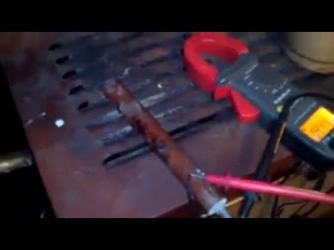 https://www.youtube.com/watch?v=PZR7HTXkXC0
I did some more research on that and found that if you use a magnesium rod and copper, it works a lot better....something about where those 2 metals are on the periodic table of elements and their atomic weight
anyways...I understand
12 panels 6 series 2 parallel 2100 watts, 1 XW60-150 CC, 16 trojan 6V batteries 8 series 2 parallel 450 Ah, 1 XW 6848 pro, 1 5500 watt champion inverter generator( I know...I need a 12Kw ) -
you were right dave...came home wednesday and had a F63, except this time, no clunk noise when I tried to reset and the generator never made it start working right againDave Angelini said:
I attached a block of XW+ not too different than your model. I also did not think the burn mark was your problem as it would have been worse. I think your power bridge is toast and breaking down.
so I opened it up and right away smelled where the magic smoke came out and saw a dark spot on the power board ( I haven't taken it apart yet to see all the damage )
so I called the guys at inverter service center to see if they had that in stock, they told me that part was $1100. So I went to talk to randy, one of the main techs, to see if maybe he had a used one I could get, as they scavenge old units for good parts.
he just happened to have one in the repair room on the shelf ....it was out of an XW 6048, of course mine is a 4548.
We both looked at the 2 of them side by side....same part numbers and looked identical to the eye, we both came to the conclusion that it should work.
Got it home and put it in, turned on the inverter....F63, but not clunking noise as before. Re-flashed the firmware just in case that was it...nope So I did the same thing I* had been doing, starting the gen and waiting for it to work right....viola, so I decided to test if that did it.
placed the inverter in standby, held the power button down, and shut the DC breaker off.
waited a few minutes, and turned it on....F63.
now I was kinda depressed but didn't give up. I did the whole disable inverter,clear the code, start the generator, waited for the the AC to qualify...after it qualified, I did something I hadn't done before....on the inverter if you push both buttons momentarily it enables or disables the inverter...well, I cycled that real fast, after about the fourth enable the inverter started working right.
satisfied I had power for now, I went in and left it alone...same conditions, cold outside, it stayed on all night and the generator charged the batteries more rapidly than it has before. inverter worked all day today... didn't want to do it, but I had to see if it was now working if I shut it down and back on.
went out and went through the process of shutting it down...waited....turned it back on, still in standby I crossed my fingers and pushed the on button....ah the beautiful sound of relay making a sinusoidal wave
I don't know if cycling the enable disable would have made the other one work, doubtful as it made the clunk noise when it had an F63 from the start, but I wished I had tried it
not sure why the new/used one caused an F63, I'm gonna guess it was a residual fault and after running all day cleared it from memory or something
don't know why cycling enable disable fixed it....anyways, its something to try the next time you have one act up on you
and that's why we have this forum...collaboration
also want to give a shout out to the guys at inverter service center in Whitehouse Tennessee....randy, nick , jordan and the rest I didnt get names from
they have some mint condition Trace stuff there...nope they ain't selling it ...done asked
12 panels 6 series 2 parallel 2100 watts, 1 XW60-150 CC, 16 trojan 6V batteries 8 series 2 parallel 450 Ah, 1 XW 6848 pro, 1 5500 watt champion inverter generator( I know...I need a 12Kw ) -
Good to be inverting!
Usually the power bridge is almost indestructible. The gensets take their toll on it and I have seen some so poorly set-up in the config that I am amazed they keep working. Not saying you either but even though an xw will soft start charging off a genset,
If the AC settings are not right and a smaller genset is used, bad things happen. Same thing with the old SW and the Trace series.
"we go where power lines don't" Sierra Nevada mountain area
htps://offgridsolar1.com/
E-mail offgridsolar@sti.net -
still going good
my new project is gonna be trying to figure out how to get this generator to put out a cleaner waveform...at least till I can buy a big inverter generator that has 120/240......the are over $5000
I , as well as others, have been searching for this holy grail for a long time
the generator I am currently using is a tsurumi tpg 7000h dxe...it has a honda GX390 and a brushless generator head
these types are voltage regulated with capacitors, the interesting thing about this one, in the manual it says not to try and flash the capacitors because it has magnets to excite the field coil....so no diodes on the rotor either and it uses 2 capacitors instead of 1
I will continue this in another discussion though
12 panels 6 series 2 parallel 2100 watts, 1 XW60-150 CC, 16 trojan 6V batteries 8 series 2 parallel 450 Ah, 1 XW 6848 pro, 1 5500 watt champion inverter generator( I know...I need a 12Kw ) -
Most generators have a pretty clean waveform. What's the problem with yours ?
Any bad components in it ?
What are you powering that does not like the waveform ?
What's the PF of the Loads you are powering ?
At what % of continuous load, do you see poor waveform ?
understand it won't be perfect, but it could be improved with a active AVR (Active Voltage Regulator)
RPM / Throttle controls the Frequency only, the regualtor system controls the voltage
https://forum.allaboutcircuits.com/threads/portable-generator-capacitor-vs-avr.144821/
Powerfab top of pole PV mount | Listeroid 6/1 w/st5 gen head | XW6048 inverter/chgr | Iota 48V/15A charger | Morningstar 60A MPPT | 48V, 800A NiFe Battery (in series)| 15, Evergreen 205w "12V" PV array on pole | Midnight ePanel | Grundfos 10 SO5-9 with 3 wire Franklin Electric motor (1/2hp 240V 1ph ) on a timer for 3 hr noontime run - Runs off PV ||
|| Midnight Classic 200 | 10, Evergreen 200w in a 160VOC array ||
|| VEC1093 12V Charger | Maha C401 aa/aaa Charger | SureSine | Sunsaver MPPT 15A
solar: http://tinyurl.com/LMR-Solar
gen: http://tinyurl.com/LMR-Lister ,


Categories
- All Categories
- 234 Forum & Website
- 142 Solar Forum News and Announcements
- 1.4K Solar News, Reviews, & Product Announcements
- 200 Solar Information links & sources, event announcements
- 901 Solar Product Reviews & Opinions
- 256 Solar Skeptics, Hype, & Scams Corner
- 22.5K Solar Electric Power, Wind Power & Balance of System
- 3.5K General Solar Power Topics
- 6.7K Solar Beginners Corner
- 1K PV Installers Forum - NEC, Wiring, Installation
- 2.1K Advanced Solar Electric Technical Forum
- 5.6K Off Grid Solar & Battery Systems
- 430 Caravan, Recreational Vehicle, and Marine Power Systems
- 1.1K Grid Tie and Grid Interactive Systems
- 656 Solar Water Pumping
- 817 Wind Power Generation
- 624 Energy Use & Conservation
- 624 Discussion Forums/Café
- 316 In the Weeds--Member's Choice
- 75 Construction
- 125 New Battery Technologies
- 108 Old Battery Tech Discussions
- 3.8K Solar News - Automatic Feed
- 3.8K Solar Energy News RSS Feed