Connecting Bayite 6.5 multimeter
Seanadirondacks
Registered Users Posts: 20 ✭✭
Im using 18/4 awg wire. Im lost on the wiring between inverter, CC and batteries. Any help would help. Thanks!
Tagged:
Comments
-
What is the DC Bus voltage (12/24/48 volts)?
The AC inverter rated wattage (1,000 Watts, 1 kWatt, etc.)?
What is the one way cable distance from the battery bank to the DC input of the AC inverter?
What is the AC inverters output voltage?
Typically, the AC wiring is 14 AWG minimum (15 amp service) and 12 AWG [fixed typo. Thanks McGivor] for 20 Amp service). 18 AWG would be smaller than normal for a "NEC" installation (14 AWG is typically the smallest diameter wire--Although, if you have a smaller AC inverter, you could use smaller AWG wiring--It really depends on your power levels. using NEC Rated Wiring is usually better. SAE wiring for DC systems is usually not as tough insulation and lower rated working voltages).
-Bill
Near San Francisco California: 3.5kWatt Grid Tied Solar power system+small backup genset -
Typically, the AC wiring is 14 AWG minimum (15 amp service) and 20 AWG for 20 Amp service). 18 AWG would be smaller than normal for a "NEC" installation (14 AWG is typically the smallest diameter wire
Typo mistake, 12awg for 20A service1500W, 6× Schutten 250W Poly panels , Schneider MPPT 60 150 CC, Schneider SW 2524 inverter, 400Ah LFP 24V nominal battery with Battery Bodyguard BMS
Second system 1890W 3 × 300W No name brand poly, 3×330 Sunsolar Poly panels, Morningstar TS 60 PWM controller, no name 2000W inverter 400Ah LFP 24V nominal battery with Daly BMS, used for water pumping and day time air conditioning.
5Kw Yanmar clone single cylinder air cooled diesel generator for rare emergency charging and welding. -
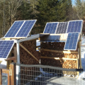
Im trying to wire this so i can monitor my solar panels. I couldn't figure where to put it.

-
Here are the instructions with various configurations, dose this help?
 1500W, 6× Schutten 250W Poly panels , Schneider MPPT 60 150 CC, Schneider SW 2524 inverter, 400Ah LFP 24V nominal battery with Battery Bodyguard BMS
Second system 1890W 3 × 300W No name brand poly, 3×330 Sunsolar Poly panels, Morningstar TS 60 PWM controller, no name 2000W inverter 400Ah LFP 24V nominal battery with Daly BMS, used for water pumping and day time air conditioning.
5Kw Yanmar clone single cylinder air cooled diesel generator for rare emergency charging and welding. -
Do you have a link to the brand/model of component you are using?
I am guessing this is remote reading volt meter (top and 2nd down are measuring the voltage drop across the shunt--precision power resistor).
The bottom two connections are - and + power to run the electronics?
Here is a video that shows how to connect: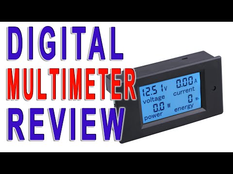 https://www.youtube.com/watch?v=eXF_bR4QUkM
Hopefully, you have the shunt resistor (something like 100 amps = 0.050 Volt drop across power resistor). The meter does the math to change the 0.0 to 0.05 volt drop to 0-100 amps. And takes volts measured gives the power (Power=Volts*Current).
Watch polarity, some meters only show "positive" current flow (0 amp on reverse current--Or simply + amps no matter direction of current).
For connecting to the solar array--As long as Voc (voltage open circuit) is 100 VDC or less, you should be fine.
In your case the "battery" is the solar array. And the "load" is the Vpanel input for the charge controller.
-Bill
Near San Francisco California: 3.5kWatt Grid Tied Solar power system+small backup genset -
Thank you! So in the #1 image for monitoring solar power. I would hook it up to the charge controller on the battery positive and negative not the solar positive and negative. Also would you still say 18awg is too small for thus device. Thanks for the help!mcgivor said:Here are the instructions with various configurations, dose this help? -
18ga should be okay unless you need to go long distance (many 100s or 1000s of feet). If the meter is fused internally, it should specify a minimum wire size. If not, I'd fuse the positive wire with something like a 3-5a inline fuse. The meter shouldn't draw much in regular operation, maybe an amp or so.Off-grid.
Main system ~4kw panels into 2xMNClassic150 370ah 48v bank 2xOutback 3548 inverter 120v + 240v autotransformer
Night system ~1kw panels into 1xMNClassic150 700ah 12v bank morningstar 300w inverter -
I was reading reviews for the device and seems many use 20awg so i thought i was stepping up with 18. In regards to wiring it to monitor incoming solar amps/watts ect. It should be hooked up to the battery positive and negative not solar correct. Thanks for the help.
-
It depends on what you're trying to measure. As Bill noted above, the meter measures current across the shunt, so you want to wire it so it gives you the info you want.
If the meter doesn't show current in both directions, and you want to measure battery current, you will have to decide on whether to measure charging current or discharging current. If the meter shows current in both directions, how you wire it to the battery will determine whether discharging shows as a positive or negative number.
The wiring of the top two (sense) wires determine what's measured. The bottom two are power to run the meter.Off-grid.
Main system ~4kw panels into 2xMNClassic150 370ah 48v bank 2xOutback 3548 inverter 120v + 240v autotransformer
Night system ~1kw panels into 1xMNClassic150 700ah 12v bank morningstar 300w inverter -
It would need to be connected to the battery for a stable power source, correct, the monitoring is taken across the shunt resistor.1500W, 6× Schutten 250W Poly panels , Schneider MPPT 60 150 CC, Schneider SW 2524 inverter, 400Ah LFP 24V nominal battery with Battery Bodyguard BMS
Second system 1890W 3 × 300W No name brand poly, 3×330 Sunsolar Poly panels, Morningstar TS 60 PWM controller, no name 2000W inverter 400Ah LFP 24V nominal battery with Daly BMS, used for water pumping and day time air conditioning.
5Kw Yanmar clone single cylinder air cooled diesel generator for rare emergency charging and welding. -
I used that same meter in my install - Two of them actually. The wire to the shunt needs to be based on the current running to / from the charge controller, assuming that is what you want to measure. However, the wires to the meter (from the shunt and tapping the voltage) have virtually no current flowing in them, so the small 22 AWG wire is fine for connecting to the meter.Off-grid cabin: 6 x Canadian Solar CSK-280M PV panels, Schneider XW-MPPT60-150 Charge Controller, Schneider CSW4024 Inverter/Charger, Schneider SCP, 8S (25.6V), 230Ah Eve LiFePO4 battery in a custom insulated and heated case.
-
Hello Please advise : I have two of these. The first one is hooked up to a 500 Amp/ 50 Mv shunt to the battery bank and seems to work fine, however I do not exceed 80 amp load on these at this time. I was inquiring if these can handle more then 100 amps on a 24 bolt system ? Also the second one I will be hooking up to regulate the charge from the solar panels, as noted in the configuration # 1, just to clarify this will be connected off the "CC " line to the battery box (Xantrax 60 pwm) and not from the disconnect to the CC? Would it make a difference ?
-
If I understand the question properly, it depends what you want to measure. Putting a shunt on the controller to battery wire will let you measure charge controller output. Putting a shunt on the combiner to controller pv input will let you measure pv output / controller input current.Off-grid.
Main system ~4kw panels into 2xMNClassic150 370ah 48v bank 2xOutback 3548 inverter 120v + 240v autotransformer
Night system ~1kw panels into 1xMNClassic150 700ah 12v bank morningstar 300w inverter


Categories
- All Categories
- 233 Forum & Website
- 140 Solar Forum News and Announcements
- 1.3K Solar News, Reviews, & Product Announcements
- 181 Solar Information links & sources, event announcements
- 894 Solar Product Reviews & Opinions
- 252 Solar Skeptics, Hype, & Scams Corner
- 22.5K Solar Electric Power, Wind Power & Balance of System
- 3.5K General Solar Power Topics
- 6.7K Solar Beginners Corner
- 1K PV Installers Forum - NEC, Wiring, Installation
- 2.1K Advanced Solar Electric Technical Forum
- 5.6K Off Grid Solar & Battery Systems
- 428 Caravan, Recreational Vehicle, and Marine Power Systems
- 1.1K Grid Tie and Grid Interactive Systems
- 656 Solar Water Pumping
- 816 Wind Power Generation
- 621 Energy Use & Conservation
- 623 Discussion Forums/Café
- 316 In the Weeds--Member's Choice
- 74 Construction
- 125 New Battery Technologies
- 108 Old Battery Tech Discussions
- 3.8K Solar News - Automatic Feed
- 3.8K Solar Energy News RSS Feed