Morningstar SureSine, a unique inverter with some down side.

Brlux
Solar Expert Posts: 73 ✭✭✭
So I know the Morningstar SureSine is a highly regarded inverter for its features, price, extremely high build quality, and unique place in it's market segment. I have a SI-300-115V-UL and I have had a few years to play with and evaluate it. It is no doubt a great sine wave inverter at a reasonable price. One of the things that gives it its unique features it that It seems to be very different topology design than other inverters in it's size category.
From what I have seen playing with and taking apart many inverters is most all modern inverters aside from the really large hard wired power ones designed for running a house like Outback or Trace/Xantrex operate in a similar way. They use a DC-DC step up converter to go from your battery voltage to some high DC like say 150-200VDC. This is done with small transformers at high frequencies like in the 100s of KHZ. This is re rectified to DC and then the second part of the inverter chops that high voltage DC up in to 60Hz AC. This is usually done with a simple H-Bridge in the case of a modified sine wave inverter or something more elaborate in the case of sine wave inverters. They usually don't have good input to output isolation and this makes it so that you don't have a true neutral to ground leg isolated and this is why you can't legally use them in a fixed hard wired installation or more accurately this is why they burn up when people try. The SureSine seems to me to be a very different approach. I found these pictures of the inside of the device here. It has a huge toroid transformer that probably accounts for 2/3 the size and weight of the device. Large transformers usually mean low frequency. There is also 2 smaller ones for filtering. It has a few power FETs of some sort and remarkably little other electronics in comparison to other sine wave inverters. My theory is that they are modulating the battery voltage to a 60Hz sine wave for direct up conversion in the toroid transformer. This allows for the isolated output of the transformer to go directly to the load. It seems very effective and surprisingly efficient. It has lower idle current and higher low load efficiency (~75W) than my 150W Samlex PST-15S-12A, Exeltech XP600, and XP1100. I love the fact it is sealed and there is no fan.
So why do I say there is a down side? This approach seems to have a down side in output power regulation and quality. I see high output voltage fluctuation like 115VAC no load 106VAC ~200W load and 99VAC at the maximum load I can get from mine before it wants to trip off, which is about 500W. It is supposed to be rated at 600W for 15 min but I have never been able to achieve anything over 500W that. The biggest shock came when looking at the output on and oscilloscope while running every day devices.

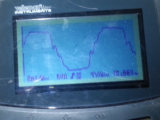
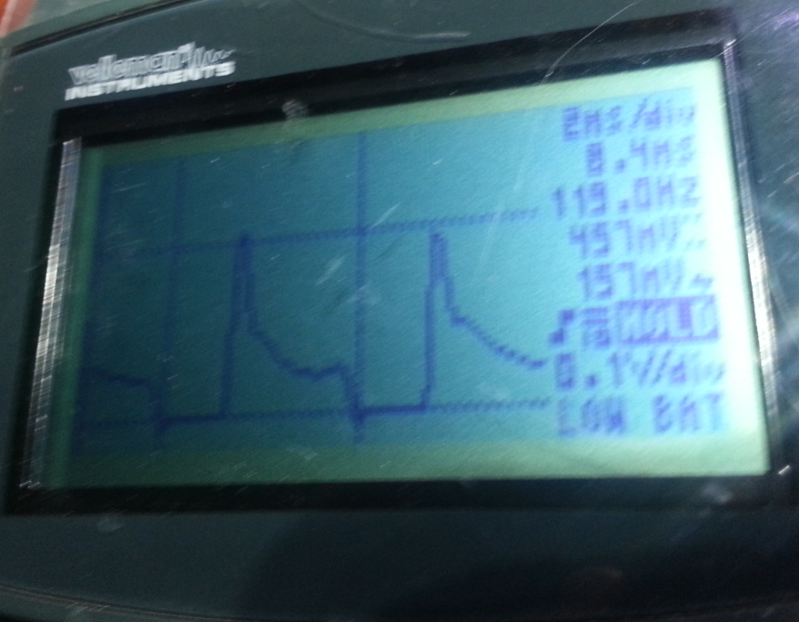
Here is what the output looked like running 68W of compact fluorescent lights. In fairness if you look at the current draw of compact fluorescent they draw nothing till the peak of the voltage wave form and then they draw several amps for a very short duration. But my other inverters seem to be able to handle these loads without distortion.
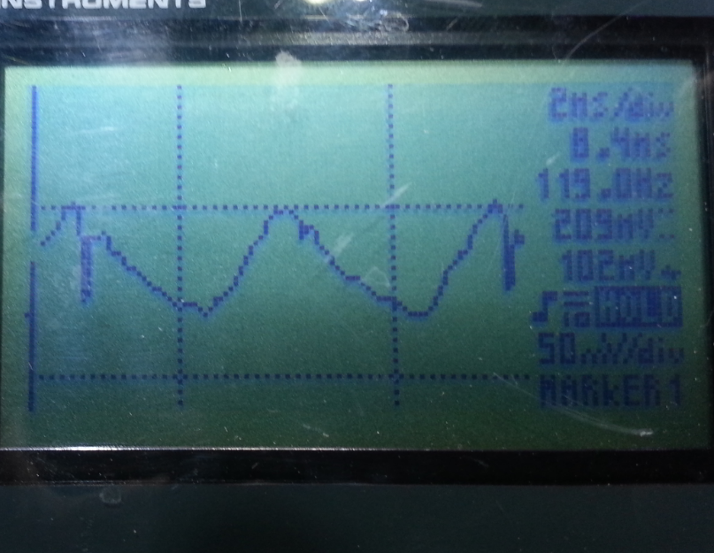
This is what it looked like running my desktop PC with dual monitors, this was about 175W load.
This lack of output regulation really struggles with less than ideal power factor loads especially switching power supplies. Unfortunately these are the types of power supplies found in our sensitive electronics that we want a sine wave inverter for running. In the case of my PC I would have been treating it much nicer with a simple modified sine wave inverter, all those spikes and ripples are hard on the power supply and I am sure there were more there than my simple scope was able to see. I have moved my computer over to the XP600 which does a fantastic job.
I do not write this solely to disparage this unique inverter, I posted this as I could only find glowing reviews of the device and nothing related to this short coming. I do still think it is a good inverter and would be a great choice for driving AC motors loads in the sub 200W range. The motors would run much cooler, last longer and get more output power to electrical consumption efficiency than they would on modified sine wave inverters.
From what I have seen playing with and taking apart many inverters is most all modern inverters aside from the really large hard wired power ones designed for running a house like Outback or Trace/Xantrex operate in a similar way. They use a DC-DC step up converter to go from your battery voltage to some high DC like say 150-200VDC. This is done with small transformers at high frequencies like in the 100s of KHZ. This is re rectified to DC and then the second part of the inverter chops that high voltage DC up in to 60Hz AC. This is usually done with a simple H-Bridge in the case of a modified sine wave inverter or something more elaborate in the case of sine wave inverters. They usually don't have good input to output isolation and this makes it so that you don't have a true neutral to ground leg isolated and this is why you can't legally use them in a fixed hard wired installation or more accurately this is why they burn up when people try. The SureSine seems to me to be a very different approach. I found these pictures of the inside of the device here. It has a huge toroid transformer that probably accounts for 2/3 the size and weight of the device. Large transformers usually mean low frequency. There is also 2 smaller ones for filtering. It has a few power FETs of some sort and remarkably little other electronics in comparison to other sine wave inverters. My theory is that they are modulating the battery voltage to a 60Hz sine wave for direct up conversion in the toroid transformer. This allows for the isolated output of the transformer to go directly to the load. It seems very effective and surprisingly efficient. It has lower idle current and higher low load efficiency (~75W) than my 150W Samlex PST-15S-12A, Exeltech XP600, and XP1100. I love the fact it is sealed and there is no fan.
So why do I say there is a down side? This approach seems to have a down side in output power regulation and quality. I see high output voltage fluctuation like 115VAC no load 106VAC ~200W load and 99VAC at the maximum load I can get from mine before it wants to trip off, which is about 500W. It is supposed to be rated at 600W for 15 min but I have never been able to achieve anything over 500W that. The biggest shock came when looking at the output on and oscilloscope while running every day devices.

Here is what the output looked like running 68W of compact fluorescent lights. In fairness if you look at the current draw of compact fluorescent they draw nothing till the peak of the voltage wave form and then they draw several amps for a very short duration. But my other inverters seem to be able to handle these loads without distortion.

This is what it looked like running my desktop PC with dual monitors, this was about 175W load.
This lack of output regulation really struggles with less than ideal power factor loads especially switching power supplies. Unfortunately these are the types of power supplies found in our sensitive electronics that we want a sine wave inverter for running. In the case of my PC I would have been treating it much nicer with a simple modified sine wave inverter, all those spikes and ripples are hard on the power supply and I am sure there were more there than my simple scope was able to see. I have moved my computer over to the XP600 which does a fantastic job.
I do not write this solely to disparage this unique inverter, I posted this as I could only find glowing reviews of the device and nothing related to this short coming. I do still think it is a good inverter and would be a great choice for driving AC motors loads in the sub 200W range. The motors would run much cooler, last longer and get more output power to electrical consumption efficiency than they would on modified sine wave inverters.
Comments
-
Perhaps the SS300 is not good for low power factor (motors, CFL, LED drivers) and that is what is causing the distortions you see, bad power factor. Looking at the battery current and voltage with the Oscope under those conditions would show something interesting if there was a bit of resistance in the DC line.Powerfab top of pole PV mount | Listeroid 6/1 w/st5 gen head | XW6048 inverter/chgr | Iota 48V/15A charger | Morningstar 60A MPPT | 48V, 800A NiFe Battery (in series)| 15, Evergreen 205w "12V" PV array on pole | Midnight ePanel | Grundfos 10 SO5-9 with 3 wire Franklin Electric motor (1/2hp 240V 1ph ) on a timer for 3 hr noontime run - Runs off PV ||
|| Midnight Classic 200 | 10, Evergreen 200w in a 160VOC array ||
|| VEC1093 12V Charger | Maha C401 aa/aaa Charger | SureSine | Sunsaver MPPT 15A
solar: http://tinyurl.com/LMR-Solar
gen: http://tinyurl.com/LMR-Lister , -
What was the DC voltage at the terminals of the inverter ? Maybe you could look at those terminals with your scope and see if the voltage is dipping low on those 120 Hz peaks ?
Distortion power factor is a tough one to beat.
boB
-
Qualification - I'm a chem not an electrical engineer - so "power factor" does not come naturally.
I am using APC Smart UPSs as inverters - for various reasons, but mainly because they are quite available in my area and are robust and "talk" to my computer (network capable). I have installed a SUA3000 - 120 volt UPS on minimalistic users - 3 ceiling fans, 6 CFLs, a LCD TV and mid sized refrigerator. This unit has good efficiency and an apparent power factor of 2700W/3000VA = 0.9. Since I'm only using the back end (DC/AC inverter with 48VDC battery bank), what is the real wattage capability of this type unit at various resistive loads? E.g. if I ran a bunch of "toasters" would I be able to get the full 3000 watts (PF~1). While running my actual loads, should I expect even less wattage than the rated 2700, assuming the overall PF of the combined loads is less than .9?
Next, the efficiency is about 95% for the SUA, so what VA should I expect to be drawn off the batteries - at these two load scenarios, i.e. does the PF of the load side really affect the battery draw?
Just curious and mainly academic, but sure helpful in understanding.3850 watts - 14 - 275SW SolarWorld Panels, 4000 TL-US SMA Sunny Boy Grid tied inverter. 2760 Watts - 8 - 345XL Solar World Panels, 3000 TL-US SMA Sunny Boy GT inverter. 3000 watts SMA/SPS power. PV "switchable" to MidNite Classic 250ks based charging of Golf cart + spare battery array of 8 - 155 AH 12V Trojans with an APC SMT3000 - 48 volt DC=>120 Volt AC inverter for emergency off-grid. Also, "PriUPS" backup generator with APC SURT6000/SURT003 => 192 volt DC/240 volt split phase AC inverter. -
Qualification - I'm a chem not an electrical engineer - so "power factor" does not come naturally.
I am using APC Smart UPSs as inverters - for various reasons, but mainly because they are quite available in my area and are robust and "talk" to my computer (network capable). I have installed a SUA3000 - 120 volt UPS on minimalistic users - 3 ceiling fans, 6 CFLs, a LCD TV and mid sized refrigerator.
You might even be able to get down towards a ~1,500 Watt AC Inverter for those loads... The ceiling fans are probably the wild card.This unit has good efficiency and an apparent power factor of 2700W/3000VA = 0.9.
In general (I have not read the specifications/manual in detail)--We are talking about the output rating here. Many of the consumer gensets/inverters/etc. are rated with Watts=VA maximum rating.
However, you will find many UPS systems (and commercial AC power sources) that may rate XXXX Watts and YYYY VA where VA>Watt rating. It does two things:- It is great for marketing documents. People see 3,000 something-- Watts/VA -- What does it matter. Larger VA output means bigger numbers for marketing documentation at a cheaper cost to manufacture (usually a bit cheaper to mfg. a 3,000 VA ups/inverter vs a 3,000 Watt inverter).
- In reality, other than pure resistive loads and "Power Factor Corrected" AC appliances, Power Factor is generally less than 1.0, and can even be down toward 0.7 for many loads, or less. So--Having a larger VA rating can actually power larger loads.
https://en.wikipedia.org/wiki/Power_factor- Power = Volts * Amps * Cos (phase angle).
Stand 45 degrees to the side of the car and pull (Cosine 45 degrees) ~0.707 -- ~71% of the force is pulling the car forward (moving car forward) and 29% of the force is pulling the car sideways (no work being done).
Another way to use Power Factor is for "non-linear" loads. Imagine you pull on the rope for 1 second and don't pull for 1 second... Only 50% of the force (the average) is used to move the car forward--But the rope must be rated for 100% load.
Many Electronic Power Supplies have a Diode/Capacitor front end. Instead of a nice smooth sine wave for current. You see zero current until the peak of the voltage wave form, then you see a large current peak. So this can give you a "poor power factor" too.
Anyway... The power factor of the output depends on the loads. If the load is an electric (resistance) heater, PF~1.0 , if however the load is a personal computer, TV, or CFL bulb, the PF may be in the range of 0.50 to 0.80
There are "power factor corrected" devices (various ways PFC can be obtained) and PF is usually around 0.95 or so.
With a 3,000 VA output rating--You can run loads up to 3,000 VA (volts * amps).
With a 2,700 Watt output rating--You can power a 2,700 Watt load = Volts * Amps * PFSince I'm only using the back end (DC/AC inverter with 48VDC battery bank), what is the real wattage capability of this type unit at various resistive loads? E.g. if I ran a bunch of "toasters" would I be able to get the full 3000 watts (PF~1). While running my actual loads, should I expect even less wattage than the rated 2700, assuming the overall PF of the combined loads is less than .9?- P = V*A*PF
- PF = P/V*A = 2,700 Watts / (3,000 VA) = 0.9 PF load
Note that, for the most part, Watts output * 1/efficiency = DC Power Input:- 2,700 Watts / 0.95 inverter eff = 2,842 DC Watts input:
- 2,842 Watts DC / 25.4 VDC (fully charged battery) = 111.9 Amps DC from 24 volt bus (nominal)
Next, the efficiency is about 95% for the SUA, so what VA should I expect to be drawn off the batteries - at these two load scenarios, i.e. does the PF of the load side really affect the battery draw?
As per the equations above...
Note, in general, the DC input current from the battery to the AC inverter's input is not a steady DC current... It is, technically a 120 Hz (60 Hz inverter) Sine 2 current wave form--So, technically, it is an RMS current (Root Mean Square) measurement.
-Bill
Near San Francisco California: 3.5kWatt Grid Tied Solar power system+small backup genset -
I found a particularly bad power factor load. It was a Black and Decker rotary tool (Dremel). On the Kill-A-Watt it was measuring 10W and 50VA power factor of 0.2. I ran it on a 150W Samlex sine wave and a 300W cheep modified sine wave inverter, the results were similar on both. The DC draw measured with a Watts-UP meter was about 15W the no load idle of the inverter is about 4-5W. Under heavy load there was some more disparity between the AC-DC watts but that could have been due to measuring the rapidly changing nature of the load as I worked the tool. So I would say most inverters should draw near the actual AC watts from the battery.
-
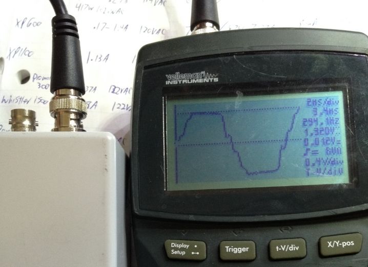
Sorry I know it has been a while since boB asked about the voltage At the inverter terminals. I was cleaning out the Garage this evening and dug this inverter out to play with again. I hooked it up to my fairly new battery bank consisting of 4 T-105s in a 2s-2p configuration. Again the computer load on this inverter according to the Kill-A-Watt is 161W, 206VA, 111VAC. I used a Fluke 289 and saw 12.215VDC at the inverter lugs 12.265VDC at the battery lugs. When I used a Mastech MS2108 DC clamp meter is showed 15.7ADC. I am connected to the bank directly with 30" of 6awg wire on each leg.
Again here is a picture of the AC waveform. This is obtained with a Powervar Power Probe 115 and velleman HPS10 portable oscilloscope. Notice the clipping at the peaks of the wave form and the rough slopes of the wave.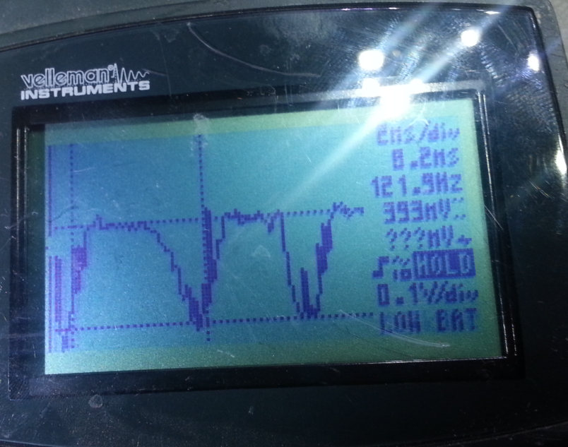
Here is what the voltage ripple looked like at the terminal lugs on the inverter. This was AC coupled as to only see and be able to zoom in on the small changes in voltage. We were getting nearly a 0.4V drop at 120Hz frequency, so it sagged as each side of the wave clipped top and bottom at 60Hz.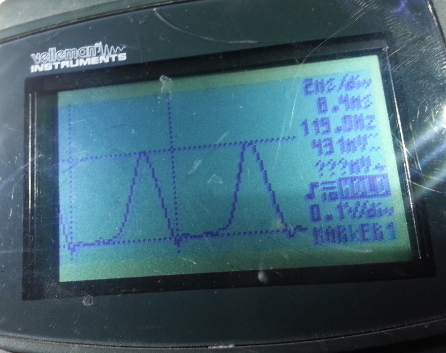
I put a DC current clamp transducer on the DC cable which gives an output of 8mv per amp. The part number on that is HST21-500A/4A in case anyone is interested and it is powered by a split + - 12V power supply. This was showing a DC spike of about 54A at 120Hz correlating with the clipped peaks of the AC voltage wave form. -
For comparison here is how a few different inverters looked.
This is the current draw on of an old trace DR2512, It has peaks around 57A and surprisingly had the lowest average current draw at 14.3A. This may be due to the very short duration high spike not being able to be properly integrated by the DC amp meter? I find it interesting that the current goes so high for such a short duration and then drops back to zero for at least 1/3 of the period. This inverter is audably loud and I wonder if these large current swings are part of the reason. 120Hz magnetic field fluctuation make metal things in it vibrate.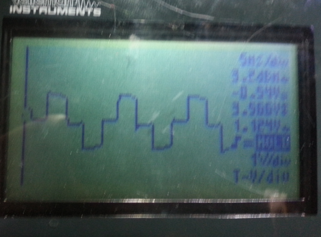
Here is the AC voltage waveform out of the DR2512. It does have some spikes around the zero crossing.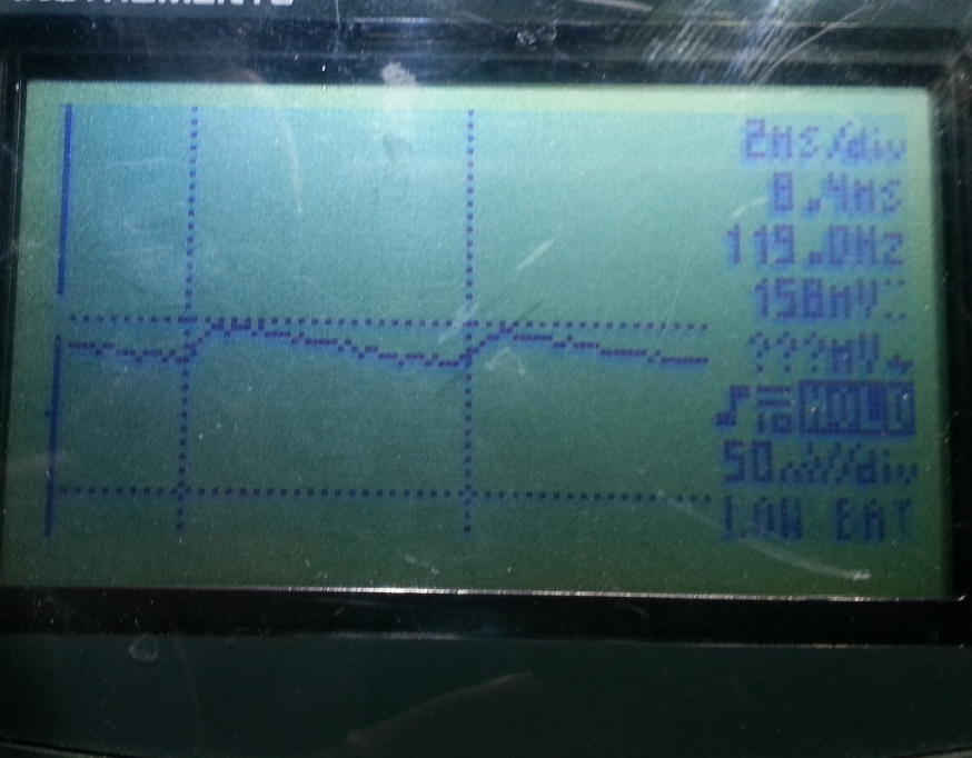
This is the DC current draw of the Exeltech XP600. It had a far more average consumption showing a peak of just under 20ADC and an average consumption of 17.5ADC.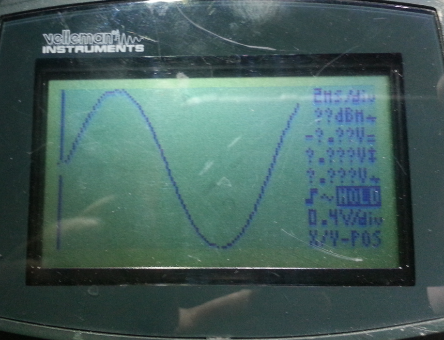
This is the XP600 AC waveform. It was very clean with just the slightest bit of distortion at the very peak of each waveform.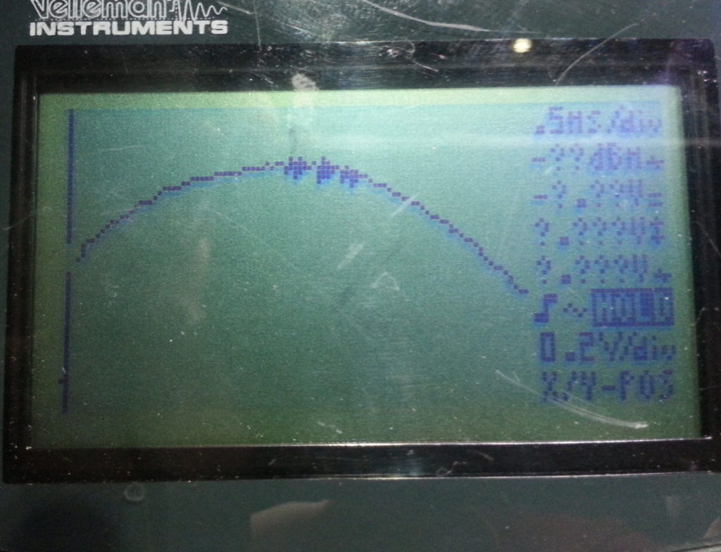
The XP600 slight distortion was only really only visible when zooming in to where the peak took up the entire screen of the scope.
-
This is the DC current consumption of a Samlex PST-15S-12A which is a small 12V 150W sine wave inverter. Note it was over loaded at around 160W here but still working. The peak was 26ADC with an average of 17.2ADC.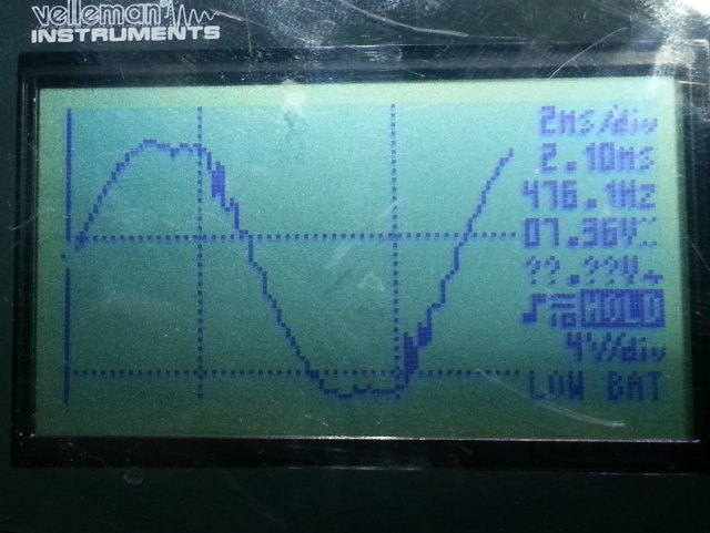
This is what the AC voltage waveform looked like on the Samlex PST-15S-12A. It is distorted but not as bad as the Sure Sine even though it was overloaded.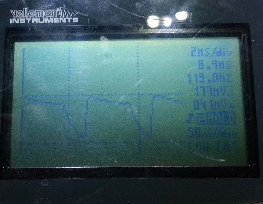
Lastly we have a cheap 300W Portawattz modified sine wave inverter. It had a peak DC current of 22ADc with an average of 15.8ADC.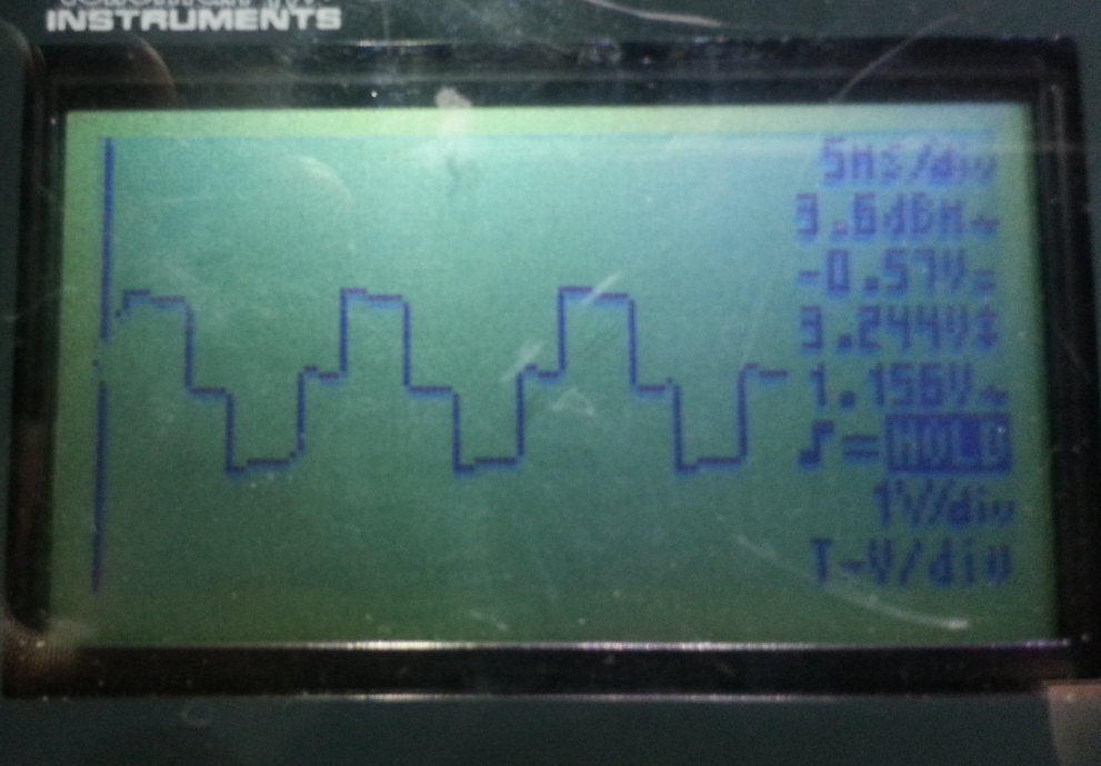
Here is what it's AC waveform looked like, also a slight distortion at the zero crossing.
-
I was using a SureSine 300, but switched it out because the high DC voltage limit of 15.5 volts was not high enough in cold weather and it would shut down when the battery bank would reach about -13 degrees C due to temperature compensated charging. Something to bear in mind if you are in a cold climate and your batteries live outside.510 watt pv, TS-MPPT 60, Exeltech XP1100, XP600 & XP250 @ 24V, 4x Trojan 105RE, Trimetric 2030, Yamaha EF2400i gen.


Categories
- All Categories
- 233 Forum & Website
- 140 Solar Forum News and Announcements
- 1.3K Solar News, Reviews, & Product Announcements
- 181 Solar Information links & sources, event announcements
- 893 Solar Product Reviews & Opinions
- 252 Solar Skeptics, Hype, & Scams Corner
- 22.5K Solar Electric Power, Wind Power & Balance of System
- 3.5K General Solar Power Topics
- 6.7K Solar Beginners Corner
- 1K PV Installers Forum - NEC, Wiring, Installation
- 2.1K Advanced Solar Electric Technical Forum
- 5.6K Off Grid Solar & Battery Systems
- 428 Caravan, Recreational Vehicle, and Marine Power Systems
- 1.1K Grid Tie and Grid Interactive Systems
- 656 Solar Water Pumping
- 816 Wind Power Generation
- 620 Energy Use & Conservation
- 623 Discussion Forums/Café
- 316 In the Weeds--Member's Choice
- 74 Construction
- 125 New Battery Technologies
- 108 Old Battery Tech Discussions
- 3.8K Solar News - Automatic Feed
- 3.8K Solar Energy News RSS Feed