Balanced MPPT system?
Comments
-
Re: Balanced MPPT system?
Rick;
This thread has gotten so long and involved with so many side issues that I don't actually remember what you are doing! Was it adding panels to an existing system? If so the connections go to the same point on the batteries.
 -
Re: Balanced MPPT system?
Cariboocoot,
It's an entirely new install using custom made semi flexible panels in a compact class A RV.
The first post has most (if not all) of the details.
Rick -
Re: Balanced MPPT system?
OK, I know I covered this before, but I am having difficulty coming to grips with a bit of electrical theory.
If I have an Inverter connected to the battery; On the positive side I have a line with a switch and a fuse then on to the battery bank positive post and the negative feeding through the main shunt and on to the battery bank negative post. Both lines are 2/0 cable.
What would happen if I then connected the solar charger (Morningstar MPPT TS-45)with a positive lead through a switch and fuse directly to the positive terminal on the inverter and the negative lead from the MPPT directly to the negative terminal on the inverter.
Will this work. I believe it is supposed to according to electrical theory, but I am having great difficulty with it. Will the 60 amp solar charger fuse blow when the inverter draws 150 amps? Will the battery monitor correctly tally the amps through the shunt??
Maybe I am just second guessing the design.....
help?
Thanks!
Rick -
Re: Balanced MPPT system?
A bit messy and convoluted but it'd work. Essentially you're moving the "common point" of the positive connection to the inverter's input post rather than the battery's post. The 2/0 wire from the inverter to the battery will handle the power going to and from the battery. The main reason for not doing this is the confusing wiring. The only time you'd have trouble is on the high Amps when the inverter draw could cause a significant drop in Voltage at the common point, far from the battery. If the wiring is sized properly this won't be noticeable. No different than multiple battery set-ups feeding a common bus bar, and the inverter and controller connected tot the bar.
The important thing for the battery monitor is that all current going in and out of the battery goes through the shunt on the negative side: BATTERY - SHUNT - CC & INV Never: BATTERY - CC - SHUNT - INV In the latter the monitor will only measure current going from the battery to the inverter.
Clear as mud, right?
We've just got to get a collection of schematics together some day. :roll: -
Re: Balanced MPPT system?
Cariboo,
Yes, Clear as mud! The wire sizes are larger than is required so should be OK, the change will allow a 4 foot decrease in wire length from the solar charger to the battery positive. Essentially the 2 AWG cables OUT from the solar charger go to the terminal studs of the inverter which already have 2/0 heavy cable going from them to the battery (and shunt) This way I do not need to run additional cable from the solar charger all the way to the battery (and shunt)
I know this diagram isn't drawn all that well, but this is the system layout.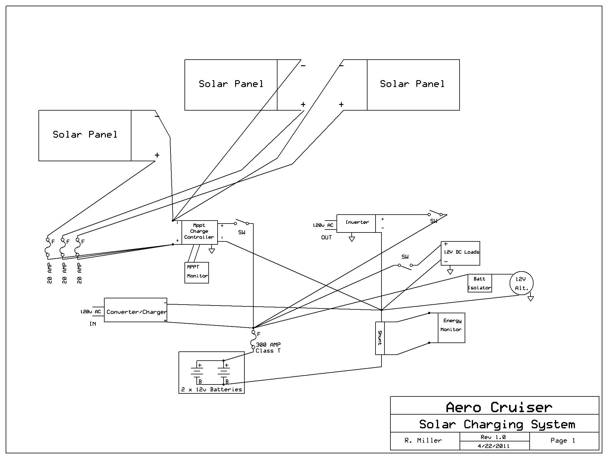
This shows the extra wiring..simply take the POSITIVE AND NEGATIVE from the MPPT controller and go to the INVERTER terminal posts. Then on to the battery and shunt.
It just didn't seem logical. Pull 150 AMPS into the inverter and the 2AWG lines connected to the charger get energized with that current as well....? Odd, I just do not want to blow any of the expensive bits up!
I am finally getting it all installed. If I can work out these small issues I should be mounting the flat semi-flexible panels permanently on the roof next weekend.
Would have been done far sooner but for the extended rainy weather.
Thanks for all your info, it has helped a great deal.
We should talk one day...bet it would be interesting!
Rick -
Re: Balanced MPPT system?
Maybe you omitted for clarity, but it appears you are relying on one fuse at the battery to handle all loads and incoming charge power. That is a definite no-no.
To be fully safe, you need to arrange it so ever circuit has its own, separate protection. The charge controller to the batteries is a different circuit than the batteries to the inverter, no matter how the wires are laid out. The same for the converter/charger and the 12 Volt loads and the alternator. The reason being that what would be an overload for one circuit would not necessarily be an overload for another. That inverter could draw hundreds of Amps and is fused for such. The charge controller will not produce that kind of current, so a 300 Amp fuse is no fuse at all to it. -
Re: Balanced MPPT system?
Cariboocoot,
I realized I pasted the older version of the diagram....D'oh!
Here is the correct one:
You'll notice extra 60AMP fuse and a few other mods. The 60AMP fuse in the new iteration would be BEFORE the 2AWG line reached the POSITIVE terminal of the INVERTER.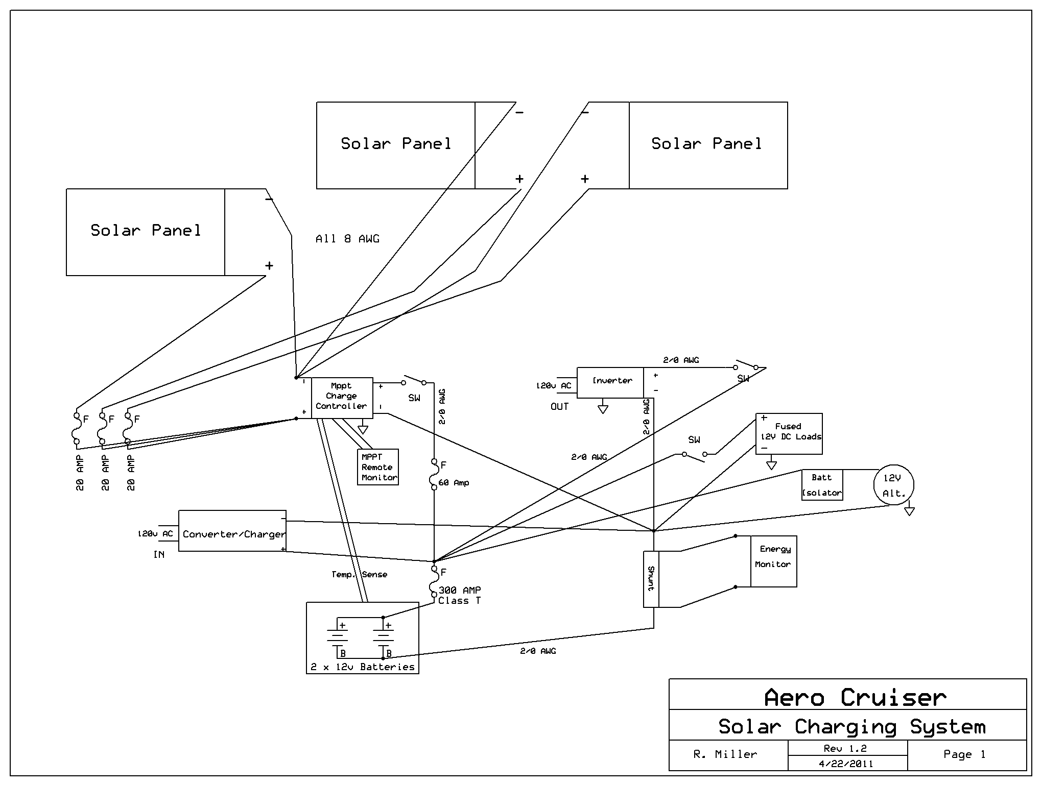
Rick -
Re: Balanced MPPT system?
That's better, but ...
You're still relying on the 300 Amp fuse for everything else?
Let's look at it this way: you'd normally have: battery post, a short conductor, the 300T, then a long conductor to the inverter. The charge controller would have its own fuse before connecting to the battery post. The battery post is the common point.
What you're doing is moving the common point. So you need to rearrange a few other things. Now you have: battery post, long conductor,* the 300T, then short conductor to the inverter. Now the common point is at '*'. The long conductor is an extension of the battery post.
And the other devices must follow suit, whether they attach at the battery post directly or at the extended common point '*'. As in: converter-charger, fuse, common point. Remember different devices have different current level potentials and thus different size wiring. You need the right size fuses to protect that wiring. A length of 10 AWG from the alternator will fry long before that 300T pops. -
Re: Balanced MPPT system?
Cariboocoot,
OK..I see what you mean. Each of the other lines to the 300 AMP T class fuse actually has a fuse within the "box" I simplified the diagram when it came to existing components. So, e.g. the CONVERTER/CHARGER has it's own main fuse on the POSITIVE terminal. And the box marked FUSED DC Loads is just a large DC distribution point with multiple lines and fuses at each.
Though, it looks like I will have to move the positive lead from the Solar MPPT to the BATTERY side of the INVERTER switch. I usually leave the inverter switch OFF and I would like to have the hard-won solar power actually Reach the battery bank!
Thanks,
Rick -
Re: Balanced MPPT system?
OK.
I installed the Morningstar MPPT 45 controller today I found a question.
Do I run the negative lead for the battery voltage sense through the shunt??? or not?
Rick -
Re: Balanced MPPT system?
You want the voltage of the battery bank... Not the voltage of the battery + shunt (~0.050 volt error from shunt).
It is not a big difference--but it helps with accuracy of charging voltage (0.10 volt difference in resting voltage is ~10% difference in state of charge).
-BillNear San Francisco California: 3.5kWatt Grid Tied Solar power system+small backup genset -
Re: Balanced MPPT system?
Ok, got it...run straight to battery!
Next question.
For Trojan batteries (Standard flooded 12v) what should the charging voltage values be???
14.6 or 14.7 or custom???
Thanks,
Rick -
Re: Balanced MPPT system?
Always a good place to start:
Trojan Battery 20 page Maintenance FAQ (PDF).
Trojan Battery Maintenance FAQ in español (PDF).
And an RV site recommended by Windsun (NAWS Admin):
For 12 Volt & RV Systems - HandyBob's long discussion and rant is about 99% right on how to make RV and similar 12 volt systems work correctly. One of the few "non NAWS" articles that we recommend.
Trojan seems to recommend higher charging voltages than "normal" (so does HandyBob)--Watch your water usage--if you have to water more often than once every 2 months (+/-)--you may want to crank down the charging voltage a bit and/or cut down the "Absorb Timer" (if your charger has one).
-BillNear San Francisco California: 3.5kWatt Grid Tied Solar power system+small backup genset -
Re: Balanced MPPT system?
Holy Cow!
Finished the install on the Morningstar TS-MPPT-45 this afternoon. How the heck can they say the terminals will take up to a 2 AWG wire and then they are WAY too small for that! I do not want to rewire, but I could never get the entire wire to fit in those terminals!
Ran the 8/3 Boat cables from the roof to the controller.
Fuse panels and disconnects in.
The only thing left is adjusting the wire lengths on the roof attaching the ring terminals and using the 3M 760 Adhesive to bond the panels to the roof. Well, after it's prepped anyhow.
If all goes well, and no rain shows up I will be online tomorrow afternoon!
Of course, Murphy was an optimist!
Rick -
Re: Balanced MPPT system?
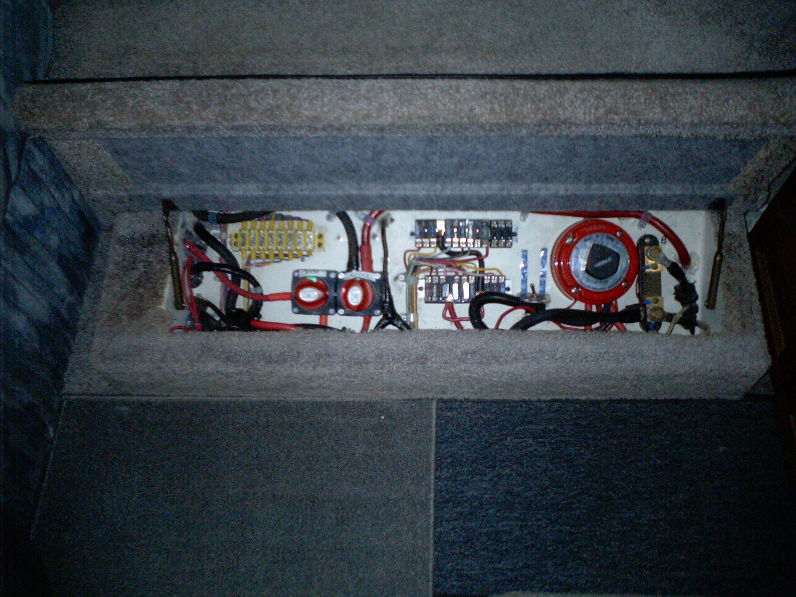
Just a quick picture of the new electrical box. This contains all the switches for the batteries, inverter and solar controller. The switch for the panels is located near the fuses for the panels on a wall by the cables from the roof.
More as I take them.
Still have to touch up a few edges and corners of the flat panels with 3M 760 and fill some holes with silicone.
Almost done!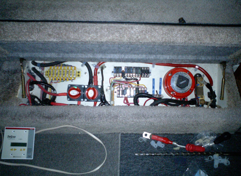
Rick -
Re: Balanced MPPT system?
A couple of later pics.
I'll get some on the roof after the 3M 760 dries and I silicone seal the wiring.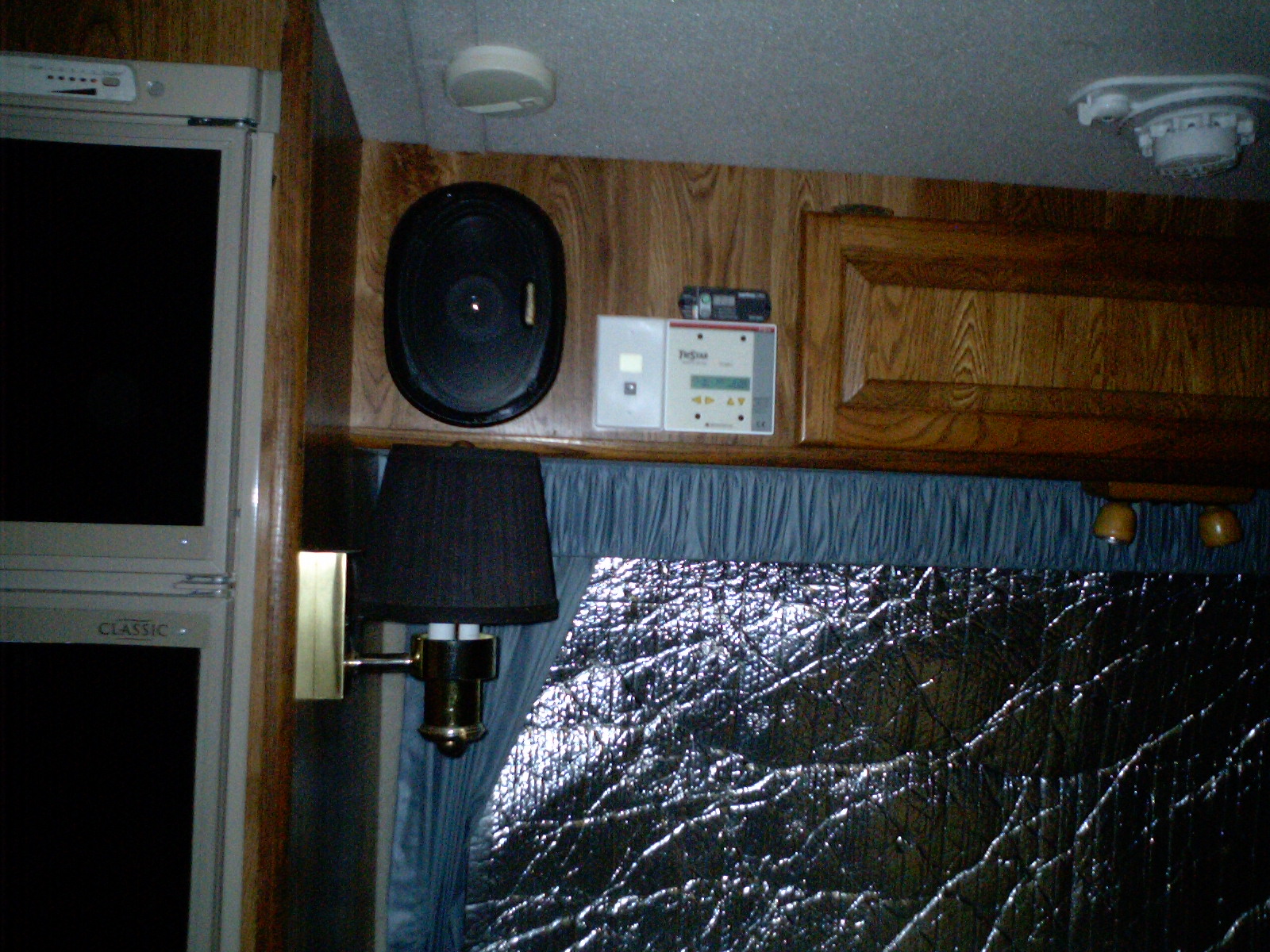
Thanks for everyones assistance, I could not have done this properly without your help!
Rick -
Re: Balanced MPPT system?
Been working on various things today so I took a photo of my small roof. If anyone recalls that what started this hunt in the first place.
All that's left to do on the roof is adhere one more feed line down to the roof, paint the junction boxes white and run a bead of silicone around each panel for security and erosion protection.
There is an odd reflection in the right side front panel...looks broken, it isn't")
Almost there!
Thanks to all who helped, especially on this forum
Rick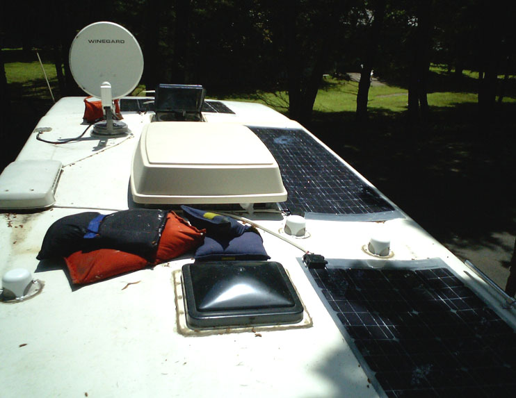
-
Re: Balanced MPPT system?
OK.
Just finished most of the finishing on the inside components of the install.
Here is a photo of the Morningstar TS-45-MPPT controller, the Xantrex 1800 Watt Inverter/transfer switch and the wiring and fuse panel for the panels.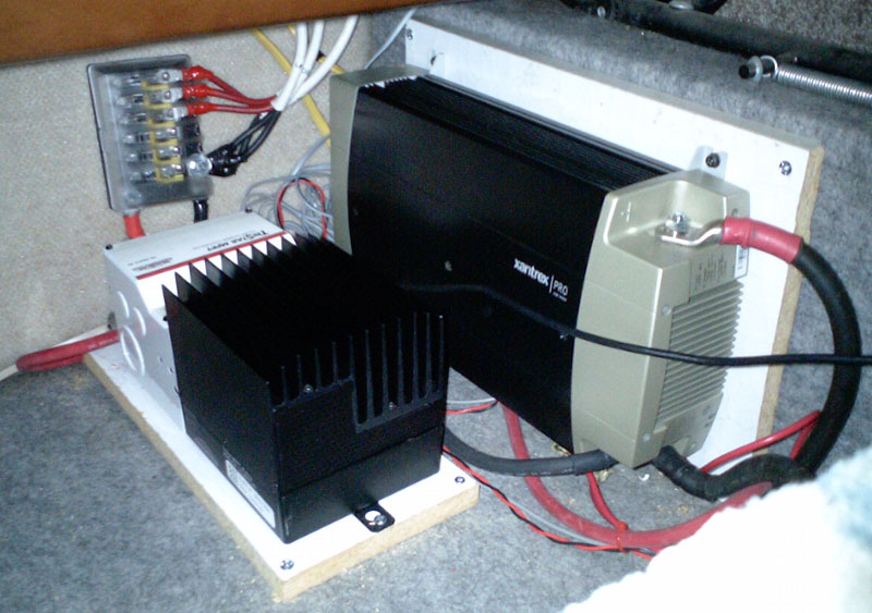
I haven't been doing run down tests yet, but without shore power I have seen 250Watts and 17.8 Amps (I have 450 Watts of ~36V panels) This was after turning on everything I could think of except the inverter.
Rick


Categories
- All Categories
- 229 Forum & Website
- 136 Solar Forum News and Announcements
- 1.3K Solar News, Reviews, & Product Announcements
- 179 Solar Information links & sources, event announcements
- 892 Solar Product Reviews & Opinions
- 252 Solar Skeptics, Hype, & Scams Corner
- 22.5K Solar Electric Power, Wind Power & Balance of System
- 3.5K General Solar Power Topics
- 6.7K Solar Beginners Corner
- 1K PV Installers Forum - NEC, Wiring, Installation
- 2.1K Advanced Solar Electric Technical Forum
- 5.6K Off Grid Solar & Battery Systems
- 428 Caravan, Recreational Vehicle, and Marine Power Systems
- 1.1K Grid Tie and Grid Interactive Systems
- 655 Solar Water Pumping
- 816 Wind Power Generation
- 620 Energy Use & Conservation
- 622 Discussion Forums/Café
- 316 In the Weeds--Member's Choice
- 74 Construction
- 125 New Battery Technologies
- 107 Old Battery Tech Discussions
- 3.8K Solar News - Automatic Feed
- 3.8K Solar Energy News RSS Feed