Balanced MPPT system?
Comments
-
Re: Balanced MPPT system?
OK...still wondering what size wires to (re) solder onto my j-boxes to minizmize loss on my runs.
New item.
Shunts.
I currently have an older Energy Monitor system with a large shunt already wired in.
After re-reading the Morningstar TS-45-MPPT controller docs, it isn;t immediately clear how amp calculations are done. Does this controller only do SOC and not cumulative amps in/out calculations..
What am I missing....aside from this mornings lack of coffee.
Rick -
Re: Balanced MPPT system?
charge controllers only determine the charge status by voltage, and time. The current measurements are only to insure it does not self-destruct, and keep you informed of the solar array health. Controller has no idea where the amps get delivered to, battery or loads, it only knows it sent so many amps out.
If you want to totalize the amps to/from your battery bank, that requires a separate battery monitor.Powerfab top of pole PV mount | Listeroid 6/1 w/st5 gen head | XW6048 inverter/chgr | Iota 48V/15A charger | Morningstar 60A MPPT | 48V, 800A NiFe Battery (in series)| 15, Evergreen 205w "12V" PV array on pole | Midnight ePanel | Grundfos 10 SO5-9 with 3 wire Franklin Electric motor (1/2hp 240V 1ph ) on a timer for 3 hr noontime run - Runs off PV ||
|| Midnight Classic 200 | 10, Evergreen 200w in a 160VOC array ||
|| VEC1093 12V Charger | Maha C401 aa/aaa Charger | SureSine | Sunsaver MPPT 15A
solar: http://tinyurl.com/LMR-Solar
gen: http://tinyurl.com/LMR-Lister , -
Re: Balanced MPPT system?
OK...so here is what is already installed:
It's an AMPLE POWER SYSTEMS Energy Monitor model #2020 It is NOT on their website as it's an older model circa ~1990 .
It has an LCD backlit display and two toggle switches on the front. One simple toggles the backlight on/off and the other switches between volts and amp/hours consumed/charged. No "fuel gauge" no bells and whistles.
It is fed via a 400A/50mV shunt.
I am thinking about switching to another monitoring system. Of course, this one is cut into my dashboard and would leave a 4 3/4" square gaping hole if removed. Not to mention all the wiring is already there to connect another unit.
I've seen the standard ones (Trimetric, Xantrex, etc) but none of them really work for this application and obviously wouldn't fit the existing hole.
I did run across the Clipper BM-1 (not CG) that looks quite promising. Does anyone have any experience with this unit??? Will it have close to the same feature set as a trimetric from bogart....
http://www.clippermarineusa.com/product.php?id=37341
I like it's look as well. Maybe I'll get the compass to...:)
Whaddya Think?
Rick -
Re: Balanced MPPT system?
I've received and/or ordered everything but the paralastic adhesive and the duplex wire.
I'm STILL not sure what size to get 8AWG? 6AWG? 10AWG?
I'm getting the feeling that this thread is so long, and covers so many topics that it has become hard to follow.
Now all I need is some cooperative weather to boost temps above 50deg F for a few days to install the system.
Rick -
Re: Balanced MPPT system?
Assuming the above:Still, What gauge wire should I be using for the runs?- Panels to controller = 12 feet (one way, MAX)
- Controller to battery = 8 feet (one way, MAX)
- Panels total 450w
- Controller max is 45Amp
- Battery bank is 390a/hrs.
- ....
- The 3 panels (450w) will be run parallel outputting ~36v into a Morningstar MPPT 45 amp charge controller feeding
Assuming 3x panels in parallel with Imp-array~15 amps @ 36 volts and using a generic voltage drop calculator, with ~1-3% voltage drop on a 12' one way cable run:- 36 volts * 3% = 1.08 volts max recommended drop
- 36 volts * 1% = 0.36 volts min cost effective drop
- 12', 14 awg, 15 amp=> 1.1 volt drop
- 12', 12 awg, 15 amp=> 0.7 volt drop
- 12', 10 awg, 15 amp=> 0.4 volt drop
- 450 watts * 1/12 volts = 37.5 volts
- 8', 2 awg, 38 amp=> 0.1 volt drop
- 8', 2/0 awg, 38 amp=> 0.06 volt drop
- 45 amps * 1.25 NEC safety factor = 56.25 amps
- 60 amp standard breaker
- 8', 2 awg, 38 amp=> 0.3 volt drop
I don't remember your maximum surge current, but assuming a flooded cell battery and C/2.5 for maximum surge current:- 3 130a/hr Trojan batteries (wet cell/deep cycle, likely SCS225s) at ~12v
- 3x130 AH * 1/2.5 = 156 amps
- 156 amps * 1.25 NEC safety factor = 195 Amps rated circuit
Assuming each battery would carry a maximum of 1/2 the current (technically, 1/3 the current, but I like to be conservative), each battery string would need 100 amp wiring or around 2 awg cable.
Remember to keep interconnect cables short and balanced between batteries.
Longer wire runs, especially at 12 VDC need to be very heavy cable to keep voltage drop low. Typically, you have about 1.0 volt maximum of allowed drop to loads (11.5 volt minimum battery voltage to 10.5 minimum load operating voltage).
Note the NEC wiring chart is very conservative--You could use this AWG chart instead and the chassis wiring rated current for your short wire runs (always check voltage drop too).
-BillNear San Francisco California: 3.5kWatt Grid Tied Solar power system+small backup genset -
Re: Balanced MPPT system?
OK...the Charge Controller and remote have arrived! I am remeasuring the wire runs to make sure I am buying enough duplex cable for the install.
Have a new issue.
Looks like the inverter was/is wired directly from the batteries with separate positive and negative cables (2/0) The negative wire does NOT go through the monitoring shunt.
Simple solution? Can I just cut the negative 2/0 cable and (with proper ends) wire the one from the battery into the shunt then from the other side of the shunt directly to the inverter negative terminal??
Is there an easier way?
The cables that run from the battery to the shunt for the rest of the 12v loads appears to be 2AWG, which is fine for nominal 12v loads it carries.
What do you all think?? Pictures and additional info below:
Rick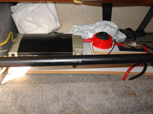
Inverter install (will be changed to compact the amount of space. The negative terminal and cable is hidden behind the horizontal pipe. The cable goes from the inverter negative directly to the battery bank negative terminal.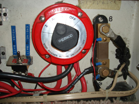
View of the Shunt and selector switch. Negative cables run from shunt out and underneath the floor. I would attach the 2/0 terminal here run left to inverter. Attach other side of shunt run out and underneath to the negative battery terminal. I am concerned the existing negative is insufficient for the inverter load. -
Re: Balanced MPPT system?
If you want the battery monitor to measure everything going in to or out of the batteries (proper install) the shunt must be in line with all connections. That is: Battery (-) - SHUNT - Everything else. As was, it apparently would only monitor current going in so you'd have no idea of the state of charge.
You're right about the wire too: has to be heavy enough to handle the max current. In this case the inverter load. The charge output is tiny compared to the potential of a fully loaded inverter. -
Re: Balanced MPPT system?
OK. I took a shot putting together a wiring diagram for my install.
I am sure there are mistakes and my artistic ability is questionable!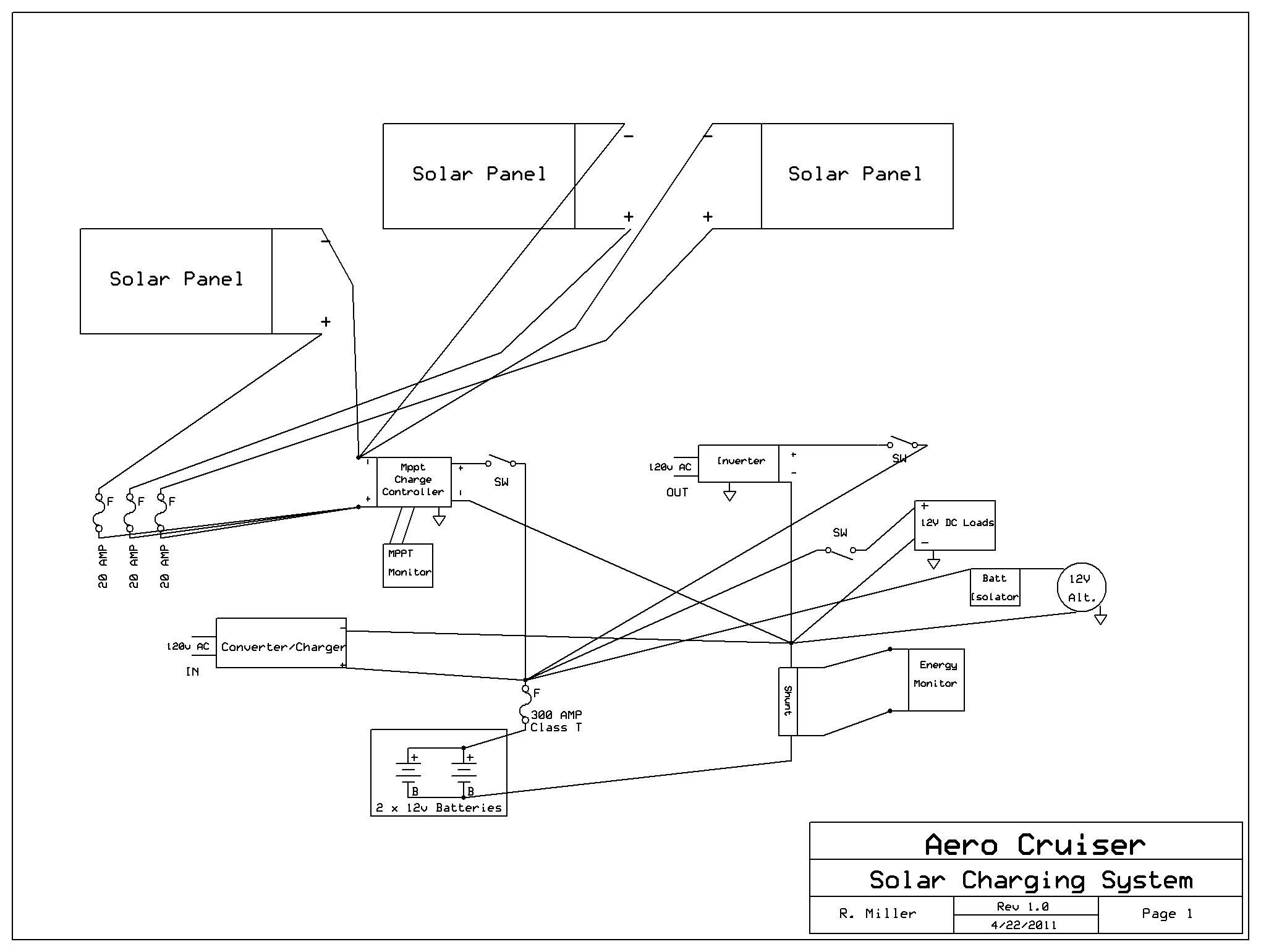
Did I miss anything??
Since this is an RV there are multiple charging sources. The Alternator will charge the house batteries after the engine battery is charged. There is the ability to isolate the engine battery from the house batteries and/or connect them all via a large Perko switch.
I show all the positive lines connected at the large Class T fuse, however there is a positive bus for all the small loads that is connected first and a large cable runs to the fuse..
Does it sound/look OK? Do I need something I haven't thought of??
Thanks, without this forum I would have made some terrible mistakes already!
Rick -
Re: Balanced MPPT system?
I see no fuse on the output from the charge controller, and there should be one.
It helps to think of the system in segments (circuits). Every segment/circuit needs a fuse or breaker.
The solar panels to the charge controller is one segment. You have fuses on each panel (20 Amp? seems a tad high but I can't remember what panels you have).
The charge controller to the batteries is another segment: another fuse required (wire sized large enough to handle maximum output current, fuse sized to protect the wire).
From the batteries to the inverter is another segment. That's where the 300 Amp fuse goes.
From the batteries to each 12 VDC device is a segment: fuse required per device, sized accordingly.
From the charger to the batteries is yet another segment requiring yet another fuse.
Make sure any disconnects can handle the maximum expected current @ VDC too. -
Re: Balanced MPPT system?
OK...thanks for the quick reply!
The only fuse that is missing is the one from the charge controller to the battery.
The other 12VDC loads are all independently fused. And the converter charger has its own fusing.
Should I move the class T so it is ONLY on the inverter positive segment??
If so, what fuse value would I need for the output end of the charge controller 50amps?? (it's a 45amp charger)
Thanks again,
Rick -
Re: Balanced MPPT system?
In my opinion the 300 Amp fuse should only be on the inverter wiring. But others may argue that it may help protect against cumulative over-load on the battery wiring due to its placement (since other DC loads are drawn off the output of this fuse).
Also my calculations show a 60 Amp fuse is in order on the 45 Amp charge controller if it is likely to run at maximum output. I might have multiplied wrong, though.
Second opinions welcome.
-
Re: Balanced MPPT system?And the converter charger has its own fusing.
To protect what? (Rhetorical question... see below.)If so, what fuse value would I need for the output end of the charge controller 50amps?? (it's a 45amp charger)
The output of the charge controller is not the main consideration when sizing the fuse.
The fuses only protect the WIRE. Each positive, load carrying wire needs to be protected from overload by a fuse or breaker.
The fuses in the converter/charger protect it against such things as reverse polarity, but since the engineers who designed it have no idea what size wire you are going to use, they couldn't - and didn't - design the fuses in the converter/charger to protect the wire.
You don't size the fuse on the charge controller circuit based on the output of the charge controller - you size the WIRE based on the output of the charge controller (and associated voltage drop), and you size the fuse to protect the wire.
So if you used a wire which is rated to 60a, then you could use a 60a fuse to protect it. But, if your charge controller only puts out 45a, then you could possibly save a buck and use a 50a fuse as long as A) it's large enough to handle the load, but") still small enough to burn up before the wire does if there is a short.
still small enough to burn up before the wire does if there is a short. -
Re: Balanced MPPT system?
OK, I've begun to bring all the pieces into the RV and test fit and lay out the wiring.
Only issue I see at the moment is the Morningstar TS-45-MPPT controller wants to be mounted vertically AND have 5 inches of clearance from the top and the bottom (and only 1" from the sides)
Any idea if it can be mounted flat on it's back with the heat sink facing up?? That would be about 12 " of clearance to the fins. Or how about sideways on a vertical surface?
Most posts I've found show it never really getting very hot. I will have ~450watts @~36v going into a nominal 12v battery system.
Thanks,
Rick -
Re: Balanced MPPT system?
The Tristar TS MPPT manual pg 17 says mount it on a vertical surface for air flow over heat sink and the clearance below: -
Re: Balanced MPPT system?
Worst case, you are looking at about 5% losses:- 450 watts * 5% = 22.5 watts
Does the area have open ventilation (low and high vents to encourage convective air flow)?
-BillNear San Francisco California: 3.5kWatt Grid Tied Solar power system+small backup genset -
Re: Balanced MPPT system?
I know the manual recommends a vertical orientation, that's why I asked the question!
The area I am looking at has quite a large volume surrounding it. There will be plenty of air flow. The issue is it's really only 14" or 15" tall. If I could mount the unit with a different orientation it would work far better.
I'll call Morningstar on Monday.
Thanks,
Rick -
Re: Balanced MPPT system?
I don't have my TS MPPT 60 mounted because I still experimenting. It sits horizontally on 40 deg angle block with clearance for air flow for the last 30 days. With 315W panels the temp log never goes above 31 deg C the last 30 days. I log it everyday for about 12 hours day light at 20 sec intervals.
It heats up when it goes to absorption mode about 1 or 2 pm. For example, during bulk charge it goes up to 275W. As soon as it goes in absorption mode the charge wattage starts going down and temperature on heat sink goes up. At float it goes to about 60W. So the exta wattage goes to the heat sink. I need a load diversion logic with relay to use the extra wattage in absorp and float mode. -
Re: Balanced MPPT system?
How close to its maximum current limit will it be run? Higher current = higher heat = need for best possible heat dissipation. Chances are it won't be putting out 45 Amps all the time. I would hope its equipped with thermal shut-down protection just in case. As MS about that. -
Re: Balanced MPPT system?
My TS MPPT 60 is a 60A unit. The max charge amp logged is about 22A and Max temp of the heat sink is about 31C. Max theoretical on my 315W pv with agm set at 14.16V absorp is about 22A.
I just don't want the MPPT to throttle down the wattage in absorption mode while the panel is producing max wattage. In other words, while the sun is producing max wattage of 300W the MPPT charger goes to absorption mode and take it down to fix volt 14.16 and amp goes down to about 2A ~ 28W. 10% used while PV can produce 300W full sun. -
Re: Balanced MPPT system?My TS MPPT 60 is a 60A unit. The max charge amp logged is about 22A and Max temp of the heat sink is about 31C. Max theoretical on my 315W pv with agm set at 14.16V absorp is about 22A.
I just don't want the MPPT to throttle down the wattage in absorption mode while the panel is producing max wattage. In other words, while the sun is producing max wattage of 300W the MPPT charger goes to absorption mode and take it down to fix volt 14.16 and amp goes down to about 2A ~ 28W. 10% used while PV can produce 300W full sun.
You've no choice. Size of the controller is irrelevant. The battery takes what is needed and the potential "extra" harvest from panels putting out full power when only a fraction is used is wasted.
That's why off-gridders are always looking for practical ways to load-shift and utilize AUX functions to make use of the power that would otherwise go missing.
Putting a 60 Amp charge controller on 300 Watts of panel is overkill, and a waste of money. -
Re: Balanced MPPT system?
I bought the MPPT controller from a guy that bought it brand new and cancelled his project for a really good price. I wanted the ethernet option. If you buy the TSMPPT45 with LCD cover the price is pretty close to the MPPT 60. Plus this is an experiment.
Once I get the feel of this, I can expand. -
Re: Balanced MPPT system?
OK, got it fuse for wire sizes. Will do.")
Next question:
Are there any benefits or differences between using a CLASS T fuse at the battery positive (or inverter) vs. an ANL fuse, both of the same Amp rating.
Thanks,
Rick -
Re: Balanced MPPT system?
Class T reacts faster. More suitable for inverters.
That last bit is my opinion; others may disagree. -
Re: Balanced MPPT system?.......
I just don't want the MPPT to throttle down the wattage in absorption mode while the panel is producing max wattage. In other words, while the sun is producing max wattage of 300W the MPPT charger goes to absorption mode and take it down to fix volt 14.16 and amp goes down to about 2A ~ 28W. 10% used while PV can produce 300W full sun.
That's when you need to watch the status, and when you leave BULK (that's when it's running the MPPT) and drops back to absorb, is when you fire up the laundry and dishwasher. Too much load, and it falls back to bulk.Powerfab top of pole PV mount | Listeroid 6/1 w/st5 gen head | XW6048 inverter/chgr | Iota 48V/15A charger | Morningstar 60A MPPT | 48V, 800A NiFe Battery (in series)| 15, Evergreen 205w "12V" PV array on pole | Midnight ePanel | Grundfos 10 SO5-9 with 3 wire Franklin Electric motor (1/2hp 240V 1ph ) on a timer for 3 hr noontime run - Runs off PV ||
|| Midnight Classic 200 | 10, Evergreen 200w in a 160VOC array ||
|| VEC1093 12V Charger | Maha C401 aa/aaa Charger | SureSine | Sunsaver MPPT 15A
solar: http://tinyurl.com/LMR-Solar
gen: http://tinyurl.com/LMR-Lister , -
Re: Balanced MPPT system?
Also check the fuse maximum voltage ratings... ANL (may) be 32 volt maximum (don't remember for sure--heading out). I think type T are rated for higher voltages...
But be careful--Many fuses, as they go up in current fuse rating, they go down in rated voltage (check rated for DC voltage/current on your bank voltage).
-BillNear San Francisco California: 3.5kWatt Grid Tied Solar power system+small backup genset -
Re: Balanced MPPT system?That's when you need to watch the status, and when you leave BULK (that's when it's running the MPPT) and drops back to absorb, is when you fire up the laundry and dishwasher. Too much load, and it falls back to bulk.
Yes, that is what I do. Run to the room and turn all the fans and salt water mix pump for my reef tank. Look at live MSView for adjustment. This is like playing with the Honda Insight or the Prius ECO mode trying to maximize the mileage back in 2001. It would be nice if I can automate it with relays on a nice sunny day. When we have two consecutive days of rain, the BM and timer turns on the AC charger. Automation based on data is the fun part. -
Re: Balanced MPPT system?
OK, I am beginning the wiring portion of the install.
Then I realized I had a dumb question.....
Do I need to put terminals on all the wiring. I.e. from the panels to the fuse block, fuse block to charge controller, all the ground points, etc.
Or is it OK to simply wrap the copper wire around the terminal and tighten down the nut?
Thanks,
Rick -
Re: Balanced MPPT system?
Rick,
Most equipment should be designed to take the stripped end of wire (insert straight end into opening, then tighten clamp screw to hold wire).
If this is a stud or screw binding type setup (where you have to wrap the wire around the threads and tighten)--You should place a crimp a ring lug on those ends--especially for stranded wires/cables. Solid wire can be bent into a U shape and hold down pretty well under a screw head. Stranded wire may loosen over time.
Usually, the installation instructions should be pretty clear about what type of wire end preparation is required for your components.
You may wish to purchase bus bars to collect your terminations... Something like these:
-BillNear San Francisco California: 3.5kWatt Grid Tied Solar power system+small backup genset -
Re: Balanced MPPT system?
BB.
That is excellent advice and I have bought both fro the install. Thanks.
Now, if it would just stop RAINING for a few days so I can do the install!!
Arrrgghhh!
Rick -
Re: Balanced MPPT system?
I've FINALLY Started the install!!
First nice day on a weekend in months and I've begun to install the system.
So far, I have removed, compacted and re-installed the AC side of the Inverter. All new AC Romex wire runs to the new location. (Lots of space rescued from the previous install)
Begin removal of the direct wired positive and negative 2/0 leads from inverter to battery (bypassed the Shunt...not anymore!)
Tomorrow, weather permitting I will run the new (much shorter) 2/0 leads from the battery positive through the disconnect switch and catastrophe fuse to the positive battery terminal and the new negative through the shunt.
Question:
Should I take positive from the same terminal as the rest of the system, or isolate it on the opposite battery positive terminal (currently I have the two older Trojan 27TMX batteries still in and will not switch until everything is finished.)?
Thanks....
Rick


Categories
- All Categories
- 233 Forum & Website
- 140 Solar Forum News and Announcements
- 1.3K Solar News, Reviews, & Product Announcements
- 181 Solar Information links & sources, event announcements
- 894 Solar Product Reviews & Opinions
- 252 Solar Skeptics, Hype, & Scams Corner
- 22.5K Solar Electric Power, Wind Power & Balance of System
- 3.5K General Solar Power Topics
- 6.7K Solar Beginners Corner
- 1K PV Installers Forum - NEC, Wiring, Installation
- 2.1K Advanced Solar Electric Technical Forum
- 5.6K Off Grid Solar & Battery Systems
- 428 Caravan, Recreational Vehicle, and Marine Power Systems
- 1.1K Grid Tie and Grid Interactive Systems
- 656 Solar Water Pumping
- 816 Wind Power Generation
- 621 Energy Use & Conservation
- 623 Discussion Forums/Café
- 316 In the Weeds--Member's Choice
- 74 Construction
- 125 New Battery Technologies
- 108 Old Battery Tech Discussions
- 3.8K Solar News - Automatic Feed
- 3.8K Solar Energy News RSS Feed