Power MOSFET question ?
XRinger
Solar Expert Posts: 529 ✭✭✭
The Power MOSFET in question is the IRFP150N shown in the diagram below.
www.irf.com/product-info/datasheets/data/irfp150n.pdf
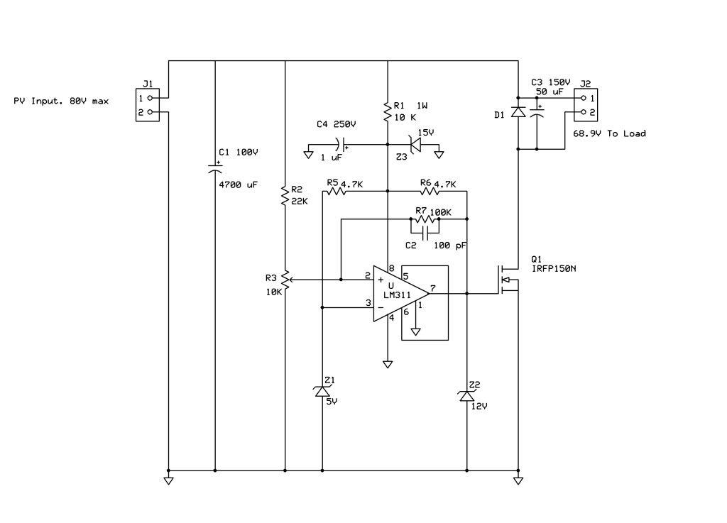
I borrowed the circuit from here.. http://www.voltscommissar.net/minimax/minimax.htm
The IRFP150N is a 100v transistor. I want to use a 115v (145v open) PV array.
My question is, can I use two of these transistors in series?
Will two of them be equal to having one 200v transistor?
Thanks,
Rich
www.irf.com/product-info/datasheets/data/irfp150n.pdf
I borrowed the circuit from here.. http://www.voltscommissar.net/minimax/minimax.htm
The IRFP150N is a 100v transistor. I want to use a 115v (145v open) PV array.
My question is, can I use two of these transistors in series?
Will two of them be equal to having one 200v transistor?
Thanks,
Rich
Comments
-
Re: Power MOSFET question ?The IRFP150N is a 100v transistor. I want to use a 115v (145v open) PV array.
My question is, can I use two of these transistors in series?
Will two of them be equal to having one 200v transistor?
Thanks,
Rich
Yes, you can but you have to make a circuit that floats the TOP FET's gate up. Can't just drive it from the same place where the bottom FETs gate drive comes from.
I would just use a 200V FET instead. IR makes some I think.
boB -
Re: Power MOSFET question ?
Oh yeah.. I see what you mean about the gate drive, (relative to ground).
I just Googled IRFP250N and it looks like a good one.
Yes sir, I think you might be right about going with a more suitable transistor..
I'll find some on Ebay. Thanks for the info.
73
Rich -
Re: Power MOSFET question ?
nope. Cant' series transistors or FETS like this, if one turns on .004 mS before the other does, they both fry.Powerfab top of pole PV mount | Listeroid 6/1 w/st5 gen head | XW6048 inverter/chgr | Iota 48V/15A charger | Morningstar 60A MPPT | 48V, 800A NiFe Battery (in series)| 15, Evergreen 205w "12V" PV array on pole | Midnight ePanel | Grundfos 10 SO5-9 with 3 wire Franklin Electric motor (1/2hp 240V 1ph ) on a timer for 3 hr noontime run - Runs off PV ||
|| Midnight Classic 200 | 10, Evergreen 200w in a 160VOC array ||
|| VEC1093 12V Charger | Maha C401 aa/aaa Charger | SureSine | Sunsaver MPPT 15A
solar: http://tinyurl.com/LMR-Solar
gen: http://tinyurl.com/LMR-Lister , -
Re: Power MOSFET question ?
Mike is correct You cant series mosfets Far to many problems, As one example if one turns on slightly before the other another is unless you know how to test and match them one will take the major share. And just to make it more difficult you are going to he to redesign the gate drive.
Look for one rated at least 180v -
Re: Power MOSFET question ?
The 200v IRFP250N looks pretty good. It's on resistance is higher,
so I'll have to be careful to do a good job on the heat sink.
I hope this thing isn't going to jam all the radio communications on the east coast..
-
Re: Power MOSFET question ?
if rfi is a concern then put it into a good metal enclosure and put more filtering on it. -
Re: Power MOSFET question ?
You have to design the circuit so that both FETs come on a close together in time as possible....
Nobody said it was easy !
boB -
Re: Power MOSFET question ?
I just found a good price on IRFP250N FETs on Ebay.
That's going to keep things simple.
The max power point voltage of the array is about 115 volts
and I plan to adjust the pot to make the FET fire at that voltage.
Hopefully, the 10 ohm load will be hit with nice strong 115 volt square wave.
With the load connected directly to the PV, the voltage is pulled down to around 75v.
So, I'm only getting about 70% to 85% of the 800w available from the array.
With this pump circuit, I hope to harvest more power under weak sun conditions,
(Manual power-point-tracking)?
And get the max power available during good sun condix..
Right now, the only time it gets close to 800w is during cloud-edge effect..
I plan to use a metal case and some filtering on the in-&-out.
I'm hoping it won't be as RF noisy as my TS-45 charger.. -
Re: Power MOSFET question ?
boB if you can show me some possible way to get 2 mosfets to both track each other within .2 of a degree c and a circuit that is going to trigger both the gates within .001 of a second I would very much like to see it. if you can I award you Electronics Designer of the year.. And will hang up my soldering iron in shame as I have no idea how it can be done reliably. -
Re: Power MOSFET question ?boB if you can show me some possible way to get 2 mosfets to both track each other within .2 of a degree c and a circuit that is going to trigger both the gates within .001 of a second I would very much like to see it. if you can I award you Electronics Designer of the year.. And will hang up my soldering iron in shame as I have no idea how it can be done reliably.
You can keep your soldering iron because I don't know if I could guarantee 2 FETs to track each other within 0.2 degree C arranged in (almost) ANY physical circuit ! You'd just be lucky if they were that close. I'm talking about parts at least, say, 50 degrees C above ambient here though.
There are usually too many other variables that will make 2 different parts that close in temperature that share the same heat sink. Air flow, tightness of the FETs against the heat sink and different layout parameters are just a few things that make them not track perfectly. Oh, and the measurement itself... Getting the thermocouple just right. What I do to test the thermocouples is to get a glass of water near boiling and then stick ALL of them in the glass and make sure they're very close. They're still not perfectly the same temperature but very close.
And within 1 millisecond ? That's quite a long time. Within 1 microsecond would be a good goal I would think.
There are a few different ways I have seen FETs in series done but my choice is with a gate drive transformer. One secondary per gate. Another problems is
making sure they share voltage when off due to differences in leakage current. That's usually done with (high value) resistors in parallel with each FET Drain-Source.
I saw one patent from Eaton that used something like the current in one FET in series help to trigger one of the other FETs it was in series with. I'd rather just use a single FET of the proper voltage as long as it's available. It's just way easier to use the higher voltage FET. However, there is an advantage to series up 2 FETs that you can't get with even a single higher voltage FET.
boB
PS... I just had an idea how you might be able to match the temperatures, and maybe within 0.2 C... (before they drift apart though) It would most likely involve adjustable software or a trimpot. -
Re: Power MOSFET question ?
If I used the metal Drain segment on body of the transistor,
they would need to be on two separate heat sinks!
No way to keep them at the same temp after they had passed some current..
Anyways, it's mootish.. 4 new 200v FETs will be here shortly..
You are the winning buyer for the item below. Thank you for your business!
Item title: 4 x IRFP250 IRFP250N IR Power MOSFET N-Channel 30A 200V
Web address: http://cgi.ebay.com/ws/eBayISAPI.dll?ViewItem&item=320594104269
Item number: 320594104269 -
Re: Power MOSFET question ?The Power MOSFET in question is the IRFP150N shown in the diagram below.
www.irf.com/product-info/datasheets/data/irfp150n.pdf
I borrowed the circuit from here.. http://www.voltscommissar.net/minimax/minimax.htm
The IRFP150N is a 100v transistor. I want to use a 115v (145v open) PV array.
My question is, can I use two of these transistors in series?
Will two of them be equal to having one 200v transistor?
Thanks,
Rich
This circuit has a serious design flaw, You state that the PV array can go up to 80 volts (max). That puts the top end of R2 at 80V, there is no guarantee that the input of the LM311 will not see excessive voltage from the array depending on where the pot is set. If the positive rail of the 311 is clamped to 15 volts, raising the positive input much past 15 volts will blow its input. At the very least, there should be an input resistor at that input which might protect it somewhat and provide better temperature tracking. You should also consider a clamp on that input. -
Re: Power MOSFET question ?
I was trying to (quickly) copy the pump controller design to use higher voltage.
http://www.voltscommissar.net/minimax/schemati.gif
But, I can see that a possible 150v from the PV could put 46v on top of R3.
The voltage on the R3 arm only needs to be around 5v..
Thanks for pointing that out, I'll need to change caps too.
Now that I'm looking at using this circuit for higher voltages. -
Re: Power MOSFET question ?I was trying to (quickly) copy the pump controller design to use higher voltage.
http://www.voltscommissar.net/minimax/schemati.gif
But, I can see that a possible 150v from the PV could put 46v on top of R3.
The voltage on the R3 arm only needs to be around 5v..
Thanks for pointing that out, I'll need to change caps too.
Now that I'm looking at using this circuit for higher voltages.
Another thing, all of the IRF series of FET's have a Vgs max of +/- 20V and the output of the comparator is pulled up to 15 volts by R6, Z2 really does not do anything and should be removed.
What type of motor are you planning to use in this application? -
Re: Power MOSFET question ?Another thing, all of the IRF series of FET's have a Vgs max of +/- 20V and the output of the comparator is pulled up to 15 volts by R6, Z2 really does not do anything and should be removed.
What type of motor are you planning to use in this application?
I copied Z2 off the original design, before I started buying transistors..
I know squat about power MOSFETs..
I've seen 10v zeniers on the gates of FETs in a few inverters, I figured
they were there to protect the gate from over-voltage.?.
I had some extra 12volters in stock... I'll delete it..")
Not using a motor, just dumping into a 10 ohm load. Heating water no less.
Yes, I've found one of the more expensive to keep water warm.. -
Re: Power MOSFET question ?I copied Z2 off the original design, before I started buying transistors..
I know squat about power MOSFETs..
I've seen 10v zeniers on the gates of FETs in a few inverters, I figured
they were there to protect the gate from over-voltage.?.
I had some extra 12volters in stock... I'll delete it..
Not using a motor, just dumping into a 10 ohm load. Heating water no less.
Yes, I've found one of the more expensive to keep water warm..
Oh Ok, non inductive load is good. Some FET's have lower Vgs ratings and that might be a reason to put a zener from Gate to Source but in this application you dont have to worry the gate will never swing higher than your 15 volt rail (providing you do the grounds properly) So lets see 70^2/10 is about 500 watts, guess that could heat a fair amount of water.
Something else is bothering me about this, at some point the array voltage is going to drop from clouds etc. The shunt regulator for the comparator will drop out of regulation. Its hard to characterize but things could go ohmic on the FET if you lose gate drive in the shade. There is a 10K on the zener and that is loaded by the reference for the positive input. You should run some tests to make sure the power dissipation in the FET does not get excessive for the boundary conditions.
Also, D1 is not required if the load is resistive, it cant hurt but it really isnt necessary. For that matter, C3 can go too, it does nothing in your application. -
Re: Power MOSFET question ?
Maybe D1 is a keeper, since I might stick something inductive on the output someday.
I had a lower power/voltage array in mind when I did the drawing.
The power supply is going to be four CS6P-200 panels in series.
www.solarinstallco.com/images/cs6p200.pdf
With a max power point voltage of 115.6v, 10 ohms is a bit of a mismatch
for the PV..
Right now, the PV can only get up to about 75v. So, instead of buying
a new load, I'm trying to see if I can bomb the load with 115v square-waves.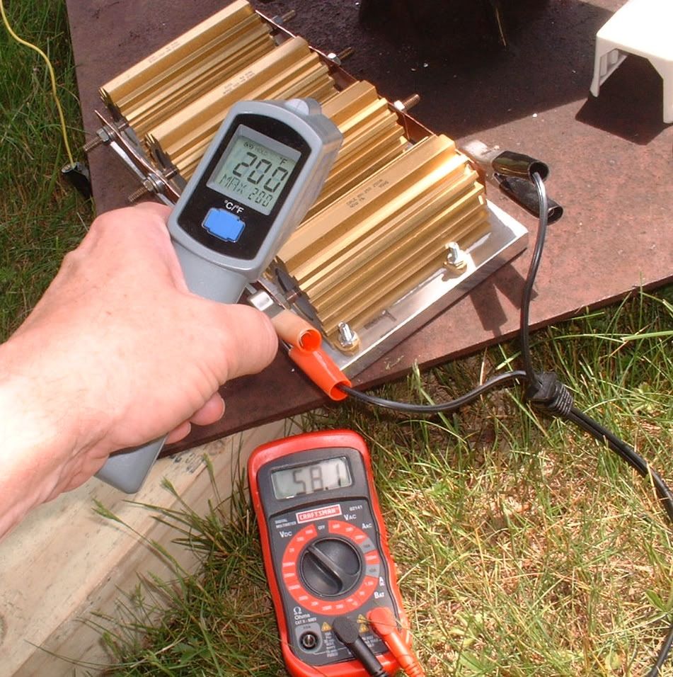
58v stinks..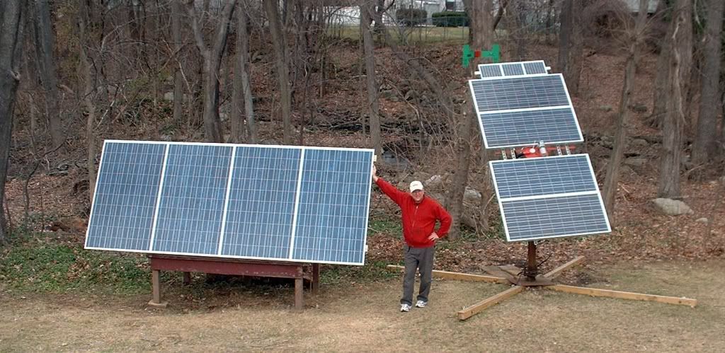
The new panels should take the 1kw load to 800w, if I feed it right..
While you are here, how much current should I have going down R2 & R3 ?
If I can use higher resistance on R2, it will make setting the pot output easier.. -
Re: Power MOSFET question ?
Since the motor winding is going to float at the maximum voltage of the panels you should connect any motor case metal to the common PV ground with a fuse in the panel hot line.
This will reduce the chance of someone getting zapped if the motor developes a winding short to the case.
The PV voltage will rise to trip ON point for voltage with very little illumination. This may not be sufficient to run motor in which case the voltage will slump causing the comparitor to disconnect. It will repeat this oscillation until illumination is enough to run motor or motor windings burns out.
It might just oscillate due to the output filter cap. -
Re: Power MOSFET question ?Since the motor winding is going to float at the maximum voltage of the panels you should connect any motor case metal to the common PV ground with a fuse in the panel hot line.
This will reduce the chance of someone getting zapped if the motor developes a winding short to the case.
The PV voltage will rise to trip ON point for voltage with very little illumination. This may not be sufficient to run motor in which case the voltage will slump causing the comparitor to disconnect. It will repeat this oscillation until illumination is enough to run motor or motor windings burns out.
It might just oscillate due to the output filter cap.
No motor.. Just the resistive load in the picture above.
The circuit should give me MPPT (Manual Power Point Tracking)..
The objective is to deliver max watts to a 10 ohm resistor.. :roll: -
Re: Power MOSFET question ?The circuit should give me MPPT (Manual Power Point Tracking)..
The objective is to deliver max watts to a 10 ohm resistor.. :roll:
Not a MPPT controller. PV is an illumination based current source. Voltage will drop to illumination current times load resistor. R7 will provide a small amount of hysterisis but not enough to prevent switch chatter.
MPP normally requires a power converter, like an inductor switcher. For a resistor load you could switch in/out multiple parallel resistors to keep panel just below its inherent diodes conduction point (MPP voltage). This would give you maximum power for available illumination current.
For example if panel is producing 6.9 amps you will get 476 watts of heat with 10 ohm load.
Assuming 68.9 vdc is MPP voltage then if panel illumination drops current to 4 amps you could get 275.6 watts. But with a fixed 10 ohm resistor you will get 160 watts, best case if the switch does not chatter.
Load resistance for max power point at 4 amps of illumination current would be 17.2 ohms. -
Re: Power MOSFET question ?Not a MPPT controller. PV is an illumination based current source. Voltage will drop to illumination current times load resistor. R7 will provide a small amount of hysterisis but not enough to prevent switch chatter.
MPP normally requires a power converter, like an inductor switcher. For a resistor load you could switch in/out multiple parallel resistors to keep panel just below its inherent diodes conduction point (MPP voltage). This would give you maximum power for available illumination current.
For example if panel is producing 6.9 amps you will get 476 watts of heat with 10 ohm load.
Assuming 68.9 vdc is MPP voltage then if panel illumination drops current to 4 amps you could get 275.6 watts. But with a fixed 10 ohm resistor you will get 160 watts, best case if the switch does not chatter.
Load resistance for max power point at 4 amps of illumination current would be 17.2 ohms.
I said "MPPT (Manual Power Point Tracking).."
The way it should work is like this..
1. PV output voltage increases, it charges up C1 as voltage rises.
2. Comparator turns on the FET at 144 volts.
3. C1 is discharged (via the FET), into the 10 ohm load.
144v/10ohms= 14.4A 144v x 14.4a = 2kw.. For, a very short time.
4. PV voltage is dragged down and the FET is switched off.
5. Goto step 1.
If the sun is bright, the cycle will repeat rapidly. A string of 144 volt pluses
will drive the 10 ohm load, fast as the 800w of PV can recharge C1..
I'm hoping that the load will heat up, to the tune of 800 watts.. -
Re: Power MOSFET question ?
At 800W, your load resistors and mounting plate will get way too hot. Those resisters are spec'd with infinite heat sink. Consider how much heat a room heater puts out on Low setting, those resistors are not made to run that hot.Powerfab top of pole PV mount | Listeroid 6/1 w/st5 gen head | XW6048 inverter/chgr | Iota 48V/15A charger | Morningstar 60A MPPT | 48V, 800A NiFe Battery (in series)| 15, Evergreen 205w "12V" PV array on pole | Midnight ePanel | Grundfos 10 SO5-9 with 3 wire Franklin Electric motor (1/2hp 240V 1ph ) on a timer for 3 hr noontime run - Runs off PV ||
|| Midnight Classic 200 | 10, Evergreen 200w in a 160VOC array ||
|| VEC1093 12V Charger | Maha C401 aa/aaa Charger | SureSine | Sunsaver MPPT 15A
solar: http://tinyurl.com/LMR-Solar
gen: http://tinyurl.com/LMR-Lister , -
Re: Power MOSFET question ?Maybe D1 is a keeper, since I might stick something inductive on the output someday.
While you are here, how much current should I have going down R2 & R3 ?
If I can use higher resistance on R2, it will make setting the pot output easier..
I was going to comment on that as well, Your pot should have wing resistors on the top and bottom to limit the range of the comparator trip points to the area of operation you plan on running this in.
With that said, the current in the string will not affect the operation too much. I like to set things up for about 1ma or so in the pot. For greater noise immunity you should put a small cap across the pot wiper to clean up any garbage, 0.1 uF is good enough.At 800W, your load resistors and mounting plate will get way too hot. Those resisters are spec'd with infinite heat sink. Consider how much heat a room heater puts out on Low setting, those resistors are not made to run that hot.
His load is submerged in a tank of water, not an issue unless the "core" gets uncovered. -
Re: Power MOSFET question ?The power supply is going to be four CS6P-200 panels in series.
www.solarinstallco.com/images/cs6p200.pdf
With a max power point voltage of 115.6v, 10 ohms is a bit of a mismatch
for the PV..
Right now, the PV can only get up to about 75v. So, instead of buying
a new load, I'm trying to see if I can bomb the load with 115v square-waves.
Umm....
You need to spec out the Mosfet to handle the maximum OPEN CIRCUIT voltage, plus a bit extra overhead for cold weather.
The voltage rating on a FET is for when it is OFF, as in "Open Circuit".
With cold weather, the open circuit voltage of 4 of those panels in series could be 160V or higher.
I think you've decided on a 200V part, that should be ok. A 150V part would not be ok. -
Re: Power MOSFET question ?At 800W, your load resistors and mounting plate will get way too hot. Those resisters are spec'd with infinite heat sink. Consider how much heat a room heater puts out on Low setting, those resistors are not made to run that hot.
The array-load has been running at 75-85% of full power for a while now,
and no ill affects have been seen. Those are (4) 40 ohm 250w resistors,
bolted(with heat sink compound under them) to a large piece of aluminum,
which sits on a flat surface inside my steel boiler.
There is a thin layer of heat conductive material between the two surfaces.
It seems to be maintaining 10 ohms.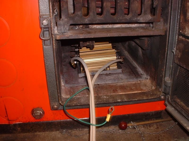
The boiler is an HS Tarm oil burner, that can also burn wood & coal.
The heater is in the ash cleanout chamber. The power wire comes in via a hole in the door.
On the left side of the pic, you can see 3 cover punch-outs.
There are 2" plumbing plugs under them. Holes for regular heating elements..
Which is an option I'm thinking about.
http://ecorenovator.org/forum/solar-power/1496-anyone-familiar-1-electric-hot-water-heating-element-hardware.html -
Re: Power MOSFET question ?Umm....
You need to spec out the Mosfet to handle the maximum OPEN CIRCUIT voltage, plus a bit extra overhead for cold weather.
The voltage rating on a FET is for when it is OFF, as in "Open Circuit".
With cold weather, the open circuit voltage of 4 of those panels in series could be 160V or higher.
I think you've decided on a 200V part, that should be ok. A 150V part would not be ok.
Open is rated for 145 volts. So 200v should be good. Max should be under 170.. -
Re: Power MOSFET question ?I was going to comment on that as well, Your pot should have wing resistors on the top and bottom to limit the range of the comparator trip points to the area of operation you plan on running this in.
With that said, the current in the string will not affect the operation too much. I like to set things up for about 1ma or so in the pot. For greater noise immunity you should put a small cap across the pot wiper to clean up any garbage, 0.1 uF is good enough.
Since the ref is going to be 5V, I'm not sure how much of a resistor I can put under the pot. But, I will shoot for 1ma in the circuit.
The noise cap on the wiper sounds like a good idea.
My thanks to all who posted their comments and suggestions.
My knowledge of modern semiconductors is severely lacking.
But, I'm learning!
Cheers,
Rich -
Re: Power MOSFET question ?The array-load has been running at 75-85% of full power for a while now,
and no ill affects have been seen. Those are (4) 40 ohm 250w resistors,
bolted(with heat sink compound under them) to a large piece of aluminum,
which sits on a flat surface inside my steel boiler.
There is a thin layer of heat conductive material between the two surfaces.
It seems to be maintaining 10 ohms.
The boiler is an HS Tarm oil burner, that can also burn wood & coal.
The heater is in the ash cleanout chamber. The power wire comes in via a hole in the door.
On the left side of the pic, you can see 3 cover punch-outs.
There are 2" plumbing plugs under them. Holes for regular heating elements..
Which is an option I'm thinking about.
http://ecorenovator.org/forum/solar-power/1496-anyone-familiar-1-electric-hot-water-heating-element-hardware.html
Hmmm I thought you were imersing the resistors in the water, if the resistors are in the ash cleanout, does that mean you are trying to heat the water through atmospheric convection? My gut tells me that doing it that way might not be too efficient. but then again, I am an electrical engineer and not a DHW expert. -
Re: Power MOSFET question ?Hmmm I thought you were imersing the resistors in the water, if the resistors are in the ash cleanout, does that mean you are trying to heat the water through atmospheric convection? My gut tells me that doing it that way might not be too efficient. but then again, I am an electrical engineer and not a DHW expert.
Nope, 96% it's conduction. That plate transfers the heat into the floor plate in the bottom of the boiler.
There is a layer of (maybe 4" thick) of water inside the water jacket in that area.
The firebox above the clean-out chamber is blocked from the chimney with sheet metal,
and the firebox is packed full of FG insulation to slow any warm air flow.
Not the idea way to do it, but it seems to be working.
I would rather use a 120v/1000w immersion heating element (they are cheap).
So, I'm slowing learning about the plumbing that needs to be done.
Have not dug into anodes etc yet..
-
Re: Power MOSFET question ?
Well, I think it would be much better to have it in direct contact with the water because that would cool the resistors and limit the max temp to 212F. What you are doing is heat sinking, there will be delta T's across each thermal junction (resistor to plate, plate to boiler floor) so it is conceivable that the resistors will be considerably hotter than the water. First, make sure to use silver based heatsink paste, silicon based breaks down over time over 200F. also try to make intimate mechanical contact between the plate and the boiler, then use the paste. You should put overtemp protection on the resistors just in case, 200 F is quite hot for those resistors.
ETA: I checked out a similar tyco part (40 ohms / 250W) and at 100C you are just at the derating point.


Categories
- All Categories
- 233 Forum & Website
- 140 Solar Forum News and Announcements
- 1.3K Solar News, Reviews, & Product Announcements
- 181 Solar Information links & sources, event announcements
- 895 Solar Product Reviews & Opinions
- 252 Solar Skeptics, Hype, & Scams Corner
- 22.5K Solar Electric Power, Wind Power & Balance of System
- 3.5K General Solar Power Topics
- 6.7K Solar Beginners Corner
- 1K PV Installers Forum - NEC, Wiring, Installation
- 2.1K Advanced Solar Electric Technical Forum
- 5.6K Off Grid Solar & Battery Systems
- 428 Caravan, Recreational Vehicle, and Marine Power Systems
- 1.1K Grid Tie and Grid Interactive Systems
- 656 Solar Water Pumping
- 816 Wind Power Generation
- 621 Energy Use & Conservation
- 623 Discussion Forums/Café
- 316 In the Weeds--Member's Choice
- 74 Construction
- 125 New Battery Technologies
- 108 Old Battery Tech Discussions
- 3.8K Solar News - Automatic Feed
- 3.8K Solar Energy News RSS Feed