Off-Grid Barndominium inverter suggestions
Comments
-
Those are interesting options and I'll be sure to look into them. Between this and what Mike95490 suggested (Logging Voltmeter), it gave me an idea that evolved as I typed this out. An Arduino and appropriate resistors (voltage divider) would make for a tidy means of accomplishing this, with the appropriate code. Last time I played around with an Arduino was nearly 10 years ago, I built a gauge cluster calibration tester. Puts out all the signals that one might realistically see going to a car's gauges, so you can calibrate each one in case of modification, repair, engine/transmission swap, etc.BB. said:Modern Integrated charge controllers/AC inverter/and even some BMS equipped Li Ion batteries do that--And are even Internet connected (data, configuration, alarms).
Another option is that some charge controllers (Midnite with their Wizbang Jr. remote battery current sense and possibly Outback with their "Flexnet" system).
As you get more complex--There is more to configure, more functions, and possibly a bit more to debug if/when things go wrong.
-Bill
Found some discussion on the subject in these links, including one with a custom PCB and suitable specs for measuring a 48v system
https://forum.arduino.cc/t/measure-solar-battery-voltage-max-48v-5a/193600
https://openenergymonitor.org/forum-archive/node/11011.html
For this, each 48v bank gets fed into the Arduino on a dedicated I/O pin (after being reduced to 0-5v via a voltage divider), then the data is output on another I/O pin to the appropriate 7-segment RGB displays (https://www.sparkfun.com/products/13999) where it gets scaled back up and displayed as numeric voltage, in different colors based on approximate SOC. For example:
White: Charging (50.4v or more)
Blue: 85-100% (49.6-50.4v)
Green: 65-85% (49.2-49.6v)
Yellow: 50-65% (48.8-49.2v)
Red: 50% or less (48.8 or less)
Flashing Red: Problem (48.0v or less)
Plus, the nice thing about Arduinos is they're cheap and completely standardized. Around $13 shipped on Ebay for an Arduino Mega2560 and $5-7 for a SD card datalogging shield with real-time clock functionality that drops right onto the Arduino. I figure logging the data every hour should be plenty for diagnostic purposes. SD cards are cheap, it's logging maybe 100 kb per day if done in a text file, and one 8gb card would last for decades. It should be able to write the data pretty quick, just the timestamp and the voltage of each bank with a tab space between them. And with a little more work, it COULD be set up to upload the data at set intervals via GSM or Lan/Wifi, with the appropriate shield boards.
The rest is writing the code to make this sorcery work. Now if only I didn't suck at soldering and writing code...
-
For Lead Acid family batteries... Voltage by itself is not very accurate at estimating actual State of Charge.
The "better" Battery Monitors typically use a shunt resistor in the negative lead to the battery bank and measure Amp*Hours in and out... With some fuzziness as the bank approaches full charge.
More or less, Lead Acid batteries are near 100% Amp (current) efficient. Voltage/Power wise, they are closer to 80% efficient (for FLA type). Where FLA batteries are less AH efficient is the last 90% to 100% Charging--Much of the energy goes into gassing and heating the battery.
If you are interested in DIY battery monitoring and why things are done the way the are (or should be), this website has a lot of detailed information about how (mostly lead acid) batteries behave under load, under charge, etc.:
http://www.smartgauge.co.uk/technical1.html
-BillNear San Francisco California: 3.5kWatt Grid Tied Solar power system+small backup genset -
Right as I was clicking post, I found a Hall Effect sensor for measuring current. In short, it sits at 2.5v when the system is neutral. While charging, it goes above 2.5v, proportional to charge rate and under 2.5v when discharging (current moving opposite direction). Theoretically, it shouldn't be too hard to add the right code to operate and log from these too. Arduino Mega2560s have a TON of programmable I/O available, so the hardest part would be scaling to suit the 0-254 and 256-1023 bit ranges for discharge and charge respectively.
-
Can turn into a very interesting project.... From what little I know, you may have drift issues with Hall Effect Transistors (open loop type).
And be aware that you are not measuring "DC current", but pulsed DC current with DC to AC single phase inverters (typically 120 Hz "sine squared" current wave form). So you will either need a low pass filter or fast enough sampling to get accurate numbers for RMS current values and avoid aliasing or beating against the current wave forms.
In solar, most of the time, just use precision shunt resistor to give you 0-50 or 0-100 mV full scale current measurements--In the battery "ground" return circuit (so that your measured sense voltages are always near zero volts relative to ground).
https://www.solar-electric.com/residential/meters-monitoring.html?product_list_limit=all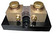
-BillNear San Francisco California: 3.5kWatt Grid Tied Solar power system+small backup genset -
I'm fairly familiar with using a shunt to measure current. I have the same setup in my jumper cables and bench 12v power supply, comes in really handy when testing things like lights, switches, etc. The only issue I can see is determining current flow direction. I want to have the monitoring system at the battery bank (before the inverter) so it measures exactly what the batteries are seeing, and the display colors reflecting what is going on. White for charging, Blue for when between 85 and 100% and not charging, etc.
Here's the link that referenced the Hall Effect Sensor on a 48v system, post #9:
https://forum.arduino.cc/t/measuring-48v-dc-battery-system-and-high-amps/328419/8This is the Transducer they suggest, capable of up to 300A:
Looks like the manufacturer, LEM, makes them in several ranges, from 50A to 600A. For a projects like this, 100A or 200A should be plenty of range and still have good resolution for logging. Plus, it works natively with the Arduino's 0-5v input too. Definitely worth an experiment.
EDIT: I incorrectly described the Arduino bit ranges above. They would be 0-510 for battery discharging and 513-1023 for battery charging. 511-512 would be neutral (not charging or discharging batteries). The HASS 50-S sensor can measure 150A in both directions, so I think it would do the job quite well. Each step is roughly 0.29A if using the entire 0-1023 bit range. The code's logic for this would be summarized as follows:Read Real-Time Clock (set to non DST time, GMT-5 time zone)If "Seconds" is "00" or "30", Execute "Operation Datalog"Execute "Operation 1": (Read Pin 2 State (0-5v), Execute "Voltage" Output Equation, Output to Display)Execute "Operation 2": (Read Pin 1 State (0-5v), Execute "Current" Output Equation, Output to Display)If Read count is divisible by "30", Execute "Write to SD card" (Read every 30 seconds, Write to SD card every 15 minutes)Repeat for next Parallel string of Battery Bank
30 seconds should be more than enough time for the code to run for every 48v string of batteries, and it would log the data to the SD card every 15 minutes.
-
Hall Effect Sensors are only good for gross measurements. So it could make the decision of Charging or Discharging. But you would still need a shunt ( a stable low value resistor that develops a precise voltage + or - ( charging/Discharge ) for the measuring system.
Hall Effect Sensors drift quite a bit, daily !
Powerfab top of pole PV mount | Listeroid 6/1 w/st5 gen head | XW6048 inverter/chgr | Iota 48V/15A charger | Morningstar 60A MPPT | 48V, 800A NiFe Battery (in series)| 15, Evergreen 205w "12V" PV array on pole | Midnight ePanel | Grundfos 10 SO5-9 with 3 wire Franklin Electric motor (1/2hp 240V 1ph ) on a timer for 3 hr noontime run - Runs off PV ||
|| Midnight Classic 200 | 10, Evergreen 200w in a 160VOC array ||
|| VEC1093 12V Charger | Maha C401 aa/aaa Charger | SureSine | Sunsaver MPPT 15A
solar: http://tinyurl.com/LMR-Solar
gen: http://tinyurl.com/LMR-Lister , -
mike95490 said:Hall Effect Sensors are only good for gross measurements. So it could make the decision of Charging or Discharging. But you would still need a shunt ( a stable low value resistor that develops a precise voltage + or - ( charging/Discharge ) for the measuring system.
Hall Effect Sensors drift quite a bit, daily !
A shunt is fine, lower voltages are easier for an Arduino to understand and translate back into current measurements. Pretty sure there are a few arduino current meter code demos floating around the net. Now comes to the fun part:
Since the panel array is sized to meet average daily (as in a full 24 hours) usage in 3 hours, how exactly could the battery bank (sized for 10 days of average-load usage with zero sun) sulphate so quickly when the solar panel array is keeping it at or near full charge under almost all conditions?
-
This week: ( unless I missed the part about you installing 10x the normal number of panels. )

I burned a bit (3 gallons ) of generator fuel that week.
In bad weather, once the FLA batteries get below 80% full ( some are 75%) , sulfation starts, and each day the batteries get lower, some more sulfation hardens up on the plates. Once hardened, it becomes difficult to remove and restore the battery to full capacity.
Powerfab top of pole PV mount | Listeroid 6/1 w/st5 gen head | XW6048 inverter/chgr | Iota 48V/15A charger | Morningstar 60A MPPT | 48V, 800A NiFe Battery (in series)| 15, Evergreen 205w "12V" PV array on pole | Midnight ePanel | Grundfos 10 SO5-9 with 3 wire Franklin Electric motor (1/2hp 240V 1ph ) on a timer for 3 hr noontime run - Runs off PV ||
|| Midnight Classic 200 | 10, Evergreen 200w in a 160VOC array ||
|| VEC1093 12V Charger | Maha C401 aa/aaa Charger | SureSine | Sunsaver MPPT 15A
solar: http://tinyurl.com/LMR-Solar
gen: http://tinyurl.com/LMR-Lister ,

Categories
- All Categories
- 233 Forum & Website
- 140 Solar Forum News and Announcements
- 1.3K Solar News, Reviews, & Product Announcements
- 181 Solar Information links & sources, event announcements
- 895 Solar Product Reviews & Opinions
- 252 Solar Skeptics, Hype, & Scams Corner
- 22.5K Solar Electric Power, Wind Power & Balance of System
- 3.5K General Solar Power Topics
- 6.7K Solar Beginners Corner
- 1K PV Installers Forum - NEC, Wiring, Installation
- 2.1K Advanced Solar Electric Technical Forum
- 5.6K Off Grid Solar & Battery Systems
- 428 Caravan, Recreational Vehicle, and Marine Power Systems
- 1.1K Grid Tie and Grid Interactive Systems
- 656 Solar Water Pumping
- 816 Wind Power Generation
- 621 Energy Use & Conservation
- 623 Discussion Forums/Café
- 316 In the Weeds--Member's Choice
- 74 Construction
- 125 New Battery Technologies
- 108 Old Battery Tech Discussions
- 3.8K Solar News - Automatic Feed
- 3.8K Solar Energy News RSS Feed