Help! Please Review My Wiring Diagram...

nberna19
Registered Users Posts: 5 ✭✭
 Hi All,
I'm trying to design my electrical system for an off grid camper van. I am a complete newb when it comes to electric so please forgive me. Attached is the first draft of my wiring diagram that I hope you all can make sense of. A few questions I'll propose in advance:
-Coming of my leisure battery I have 4 wires coming off of the negative terminal and 3 coming off of the positive terminal (I may also add an alternator charger in the future which would add 2 more wires). Is this too much coming off the terminals and should I consider wiring it all to a positive and negative busbar beforehand?
-Coming off of the leisure battery, do fuses go before or after an on/off switch?
-I'm not entirely sure of the correct fuses and gauge wire to use on each connection so please look out for this.
Thanks for any and all help,
Nick
Comments
-
I would not use a 'load' function of the charge controller, and just hook up the 12 volt loads to the batteries.
Battery connections, with 2 batteries in parallel, should be made to the positive terminal of one and the negative terminal of the other. This provide equal resistance across the batteries.
I would use breakers instead of fuses, and use them as on/off switches in an emergency.
In general, for household wiring the 3 panels should have a breaker of fuse on each panel. I have no problem with 3 12 volt nominal, panels wired without. The idea is that 2 of the panels would be able to over power the other in case of a short, but with the max of 20 volts the risk of fire in pretty much non existent between the roof of the car and the panels.
I would 'float' the system and not try to ground to the chassis.
Home system 4000 watt (Evergreen) array standing, with 2 Midnite Classic Lites, Midnite E-panel, Magnum MS4024, Prosine 1800(now backup) and Exeltech 1100(former backup...lol), 660 ah 24v Forklift battery(now 10 years old). Off grid for 20 years (if I include 8 months on a bicycle).
- Assorted other systems, pieces and to many panels in the closet to not do more projects. -
If you are going to use fuses have one for your water pump. I've had one blow because a small fan was also connected to it. The wiring on Lance is pretty good so I have pretty much left things as they are. The solar was just an add on.
-
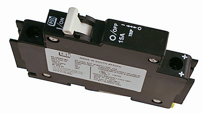
Fuses are utilized and sized to protect the wires they are connected to. Best practice is to place the fuse closest to the power source. The battery being the source of power for your loads it would be best to locate the fusing at the battery.
I'm surprised the forums host doesn't carry them so I'm only going to show a photo of them. Blue Sea has these terminal mount fuses that are IMHO the best protection for your DC wiring . They have a single version as well.
2.1 Kw Suntech 175 mono, Classic 200, Trace SW 4024 ( 15 years old but brand new out of sealed factory box Jan. 2015), Bogart Tri-metric, 460 Ah. 24 volt LiFePo4 battery bank. Plenty of Baja Sea of Cortez sunshine.
-
It is perfectly OK to link to other suppliers/vendors when answering questions... Here is the BlueSea link for LittleHarbor2's example:
https://www.bluesea.com/products/2151/Dual_MRBF_Terminal_Fuse_Block_-_30_to_300A
-BillNear San Francisco California: 3.5kWatt Grid Tied Solar power system+small backup genset -
I'd highly recommend buss bars for more than a couple of battery connections. Trying to squish more on the battery terminals is a pain, and can cause problems with lousy connections, heating, etc. My boat is like that, and adding busses is on the to-do list.Off-grid.
Main system ~4kw panels into 2xMNClassic150 370ah 48v bank 2xOutback 3548 inverter 120v + 240v autotransformer
Night system ~1kw panels into 1xMNClassic150 700ah 12v bank morningstar 300w inverter -
 Thanks for all the feedback everyone. I attached an updated diagram w/ a couple changes to note. The solar panels are wired in series, I have the charge controller, 12v fuse box, and inverter connected to positive and negative bus bars before the batteries, and I added several breakers with on/off toggles. The batteries are still wired in parallel. Let me know what you think. Thanks again!
 -
Off-grid.
Main system ~4kw panels into 2xMNClassic150 370ah 48v bank 2xOutback 3548 inverter 120v + 240v autotransformer
Night system ~1kw panels into 1xMNClassic150 700ah 12v bank morningstar 300w inverter -
Inverter fuse should be more like 100 amps maybe 120 amps the inverter should draw no more than 90 amps at 12.0 volts and 100 amps at 10 volts......but don't take your batteries that low in voltage if you want have longevity2 Classic 150, 2 Kid, 5 arrays 7.5 kw total 2ea. 2S6P Sharp NE-170/NE-165, 1ea. 12P Sanyo HIT 200, 2ea. 4/6P Sanyo HIT 200, MagnaSine MS4024AE, Exeltech XP-1100, 2 Banks L-16 battery, Rolls-Surette S-530 and Interstate Traction, Shunts with whizbangJr and Bogart Tri-Metric, iCharger i208B dc-dc buck/boost converter with BMS for small form lithium 8S 16650 or LiFePO4,
-
Thanks for the info on the inverter fuse size. What about my battery to battery wire, inverter to battery wire, and battery to bus bar wire sizes. Should those all be 2/0 AWG?
-
My personal preference is to put as big a wire on the inverter as will physically fit on the terminal, and fuse for the lesser of wire ampacity or inverter spec.
For parallel connecting batteries, IIRC there's an argument to be made that using overly large parallel connection wire for very low resistance can be counter-productive.
Off-grid.
Main system ~4kw panels into 2xMNClassic150 370ah 48v bank 2xOutback 3548 inverter 120v + 240v autotransformer
Night system ~1kw panels into 1xMNClassic150 700ah 12v bank morningstar 300w inverter -
any wire that the inverter draws power from should be rated for the inverters rated power...2/0 is a bit big for 100 amps but it will not hurt anything 2 ga wire is NEC rated at 125 amps, that is large enough, if long run use 1/0 or 2/0 to keep voltage drop down. the one thing I don't like is your battery connection scheme. go peek at http://www.smartguage.co.uk.bat_conn.html for better wiring scheme. the extra wire going to the second battery inserts some added resistance there....better have both batteries tied to the buss bars ....with equal length, equal size wire...results in more equal current balancing between the batteries. the voltage will be the same at both but the current (delivered power) will not be equal the way you diagram. the battery with the smaller wiring will be undercharged with your proposed wiring. Many system failures can be traced to poor wiring technique. better to do it on paper first and tune it before building it. there are many here that will help. Batteries are the weakest link in solar system and a huge cause of system failure
2 Classic 150, 2 Kid, 5 arrays 7.5 kw total 2ea. 2S6P Sharp NE-170/NE-165, 1ea. 12P Sanyo HIT 200, 2ea. 4/6P Sanyo HIT 200, MagnaSine MS4024AE, Exeltech XP-1100, 2 Banks L-16 battery, Rolls-Surette S-530 and Interstate Traction, Shunts with whizbangJr and Bogart Tri-Metric, iCharger i208B dc-dc buck/boost converter with BMS for small form lithium 8S 16650 or LiFePO4, -
Battery bank should be wired like this;

I missed that you were using an MPPT CC, your diagram shows parallel wiring, though you say series,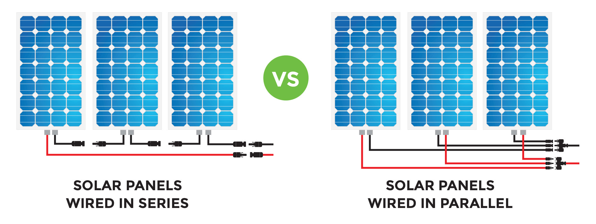
You might be money ahead to use DC breakers and a short piece of Din rail or a small din rail breaker box for both your 'fuse' and switch.
Home system 4000 watt (Evergreen) array standing, with 2 Midnite Classic Lites, Midnite E-panel, Magnum MS4024, Prosine 1800(now backup) and Exeltech 1100(former backup...lol), 660 ah 24v Forklift battery(now 10 years old). Off grid for 20 years (if I include 8 months on a bicycle).
- Assorted other systems, pieces and to many panels in the closet to not do more projects. -
whit has drawn out what I was pointing to at smartguage.....this wiring will have equal lengths of wire for both batteries. balance will be much better than what you drew.
2 Classic 150, 2 Kid, 5 arrays 7.5 kw total 2ea. 2S6P Sharp NE-170/NE-165, 1ea. 12P Sanyo HIT 200, 2ea. 4/6P Sanyo HIT 200, MagnaSine MS4024AE, Exeltech XP-1100, 2 Banks L-16 battery, Rolls-Surette S-530 and Interstate Traction, Shunts with whizbangJr and Bogart Tri-Metric, iCharger i208B dc-dc buck/boost converter with BMS for small form lithium 8S 16650 or LiFePO4, -
Thanks for all the good feedback. I think I understand now - in order for both batteries to be balanced I should have both positive terminals connected with battery A going in to the postive bus bar; while both negative terminals on the batteries are connected with an equal length/guage wire and battery B is connected to the negative bus bar. Is this correct?
-
Also, I was originally going to wire the panels in parallel but after looking at the benefits of wiring in series I think I may go that route. The only caveat is the panels are already mounted and I have a Maxxair Fan installed about 6 inches from one of the panels. Is this of any major concern when it comes to partial shading?
-
MPPT charge controllers 'need' to have input voltage about 30% high than the charging voltage, so if you have them in parallel, they won't achieve a high enough voltage to function properly. So a flooded lead acid battery bank charging at 14.5 volts would need 14.5 x 1.3 = 18.85 volts input.nberna19 said:... going to wire the panels in parallel but after looking at the benefits of wiring in series I think I may go that route.
Even if your panels have a vmp of 19 volts or above, it will lose much of that during the heat of the day. This is called the Normal Operating Cell Temperature (NOCT)value. While I couldn't find a 100 watt panel to give you for example, you may find they publish the NOCT values for their panels. Since you have 100 watt 12 volt nominal panels, they will have 36 cells. Here is an example of a Silfab panel which has 72 cells so double the voltage. They publish both the STC standard test condition values which is the 'name plate' rating, along side the NOCT values which is what you can expect during the heat of the day.
You can see the normal STC rating is 350 watts at 38.9 volts (with 72 cells) if we use half the value as if it was a 36 cell panel it would have a VMP of 38.9÷2= 19.5 volts, but in reality when hot they will only produce 35 volts as a 72 cell panel, or 17.5 volts (35÷2) as a 12 volt nominal panel. too low to allow a MPPT type charge controller to work properly.
Some manufacturers will publish this information as a minimum input voltage in their manual, so don't. The charge controller will work without the higher voltage, but be unable to convert as much of the extra wattage to usable charging current.
Home system 4000 watt (Evergreen) array standing, with 2 Midnite Classic Lites, Midnite E-panel, Magnum MS4024, Prosine 1800(now backup) and Exeltech 1100(former backup...lol), 660 ah 24v Forklift battery(now 10 years old). Off grid for 20 years (if I include 8 months on a bicycle).
- Assorted other systems, pieces and to many panels in the closet to not do more projects.


Categories
- All Categories
- 230 Forum & Website
- 137 Solar Forum News and Announcements
- 1.3K Solar News, Reviews, & Product Announcements
- 180 Solar Information links & sources, event announcements
- 892 Solar Product Reviews & Opinions
- 252 Solar Skeptics, Hype, & Scams Corner
- 22.5K Solar Electric Power, Wind Power & Balance of System
- 3.5K General Solar Power Topics
- 6.7K Solar Beginners Corner
- 1K PV Installers Forum - NEC, Wiring, Installation
- 2.1K Advanced Solar Electric Technical Forum
- 5.6K Off Grid Solar & Battery Systems
- 428 Caravan, Recreational Vehicle, and Marine Power Systems
- 1.1K Grid Tie and Grid Interactive Systems
- 656 Solar Water Pumping
- 816 Wind Power Generation
- 620 Energy Use & Conservation
- 622 Discussion Forums/Café
- 316 In the Weeds--Member's Choice
- 74 Construction
- 125 New Battery Technologies
- 107 Old Battery Tech Discussions
- 3.8K Solar News - Automatic Feed
- 3.8K Solar Energy News RSS Feed