DIY battery monitor/charger
nsaspook
Solar Expert Posts: 396 ✭✭✭
I'm building my own PIC micro-controller based battery monitor and charger control system for a small scale system.
It's using a Xantrex C40 for the solar charge controller with the PIC as the control monitor for battery state and charging for 4 arrays of cells. The first will be the primary for power to a 2kw inverter with second a manual switched backup power source. The other two cells are redundant power (small 7Ah gell types) for the controller and electronics. Most of the electronics were surplus stuff from old equipment at work or left-over projects long dead.
I plan on having about 200W of solar as the input and 4 main batteries (2 flooded DEKA DC31DT, 2 AGMs C&D UPS12-270FR in good condition pulled from various UPS systems at work). The flooded cells will be the primary with C&D as the backup.
Most of the electronics and controller wiring is already done and basic software is running. The next phase it to write the monitor module for the PIC using the Victron BMV-600S as a model for what has to be done and is needed to keep the batteries in good condition. I don't plan on a clone just making my controller do the same thing with the data it collects.
As I progress on this little project I plan to post all the software and plans for others to use. I done other internal projects with controllers but this is the first with solar and so far it's a lot of fun.
Here's a link to the first post about it and any updates will be on this thread. http://forum.solar-electric.com/showpost.php?p=52473&postcount=12
Comments
-
Re: DIY battery monitor/chargerI'm building my own PIC micro-controller based battery monitor and charger control system for a small scale system.
It's using a Xantrex C40 for the solar charge controller with the PIC as the control monitor for battery state and charging for 4 arrays of cells. The first will be the primary for power to a 2kw inverter with second a manual switched backup power source. The other two cells are redundant power (small 7Ah gell types) for the controller and electronics. Most of the electronics were surplus stuff from old equipment at work or left-over projects long dead.
I plan on having about 200W of solar as the input and 4 main batteries (2 flooded DEKA DC31DT, 2 AGMs C&D UPS12-270FR in good condition pulled from various UPS systems at work). The flooded cells will be the primary with C&D as the backup.
Most of the electronics and controller wiring is already done and basic software is running. The next phase it to write the monitor module for the PIC using the Victron BMV-600S as a model for what has to be done and is needed to keep the batteries in good condition. I don't plan on a clone just making my controller do the same thing with the data it collects.
As I progress on this little project I plan to post all the software and plans for others to use. I done other internal projects with controllers but this is the first with solar and so far it's a lot of fun.
Here's a link to the first post about it and any updates will be on this thread. http://forum.solar-electric.com/showpost.php?p=52473&postcount=12
Unless I read this wrong, I don't see how you're going to get any battery monitor to work with mis-matched batteries.
BTW, it is usually recommended that you design a system based on loads. Maybe your not expressing it clearly enough for my ol' brain, but there's some bits of your description which seem slightly out-of-whack.
If you're designing a new battery monitor, I'd suggest you set up a system that functions well first. You need to know it works before you can truly determine if your new design works, don't you? -
Re: DIY battery monitor/chargerCariboocoot wrote: »Unless I read this wrong, I don't see how you're going to get any battery monitor to work with mis-matched batteries.
BTW, it is usually recommended that you design a system based on loads. Maybe your not expressing it clearly enough for my ol' brain, but there's some bits of your description which seem slightly out-of-whack.
If you're designing a new battery monitor, I'd suggest you set up a system that functions well first. You need to know it works before you can truly determine if your new design works, don't you?
My description of the system was incomplete and disjointed.;) I'm a lot better at making things than describing how it works. (ask my boss)
The two inverter banks will have the same type batteries. The first will have two identical C&D AGMs and the other will have two identical DEKAs. The software will keep track of which is under charge with relays and adjust the parameters for it. It works fine now keeping everything charged two batteries at a time (10A solar input current at 15 volts) but with with a timer with no real feedback from the C40 on charge state so I waste solar that could be used elsewhere. I plan to link that info from the indicator led on the C40. I have sense lead from C40 indicator led to a buffer amp (uln2003a) that is a input to the controller. When the led is solid (charged) and my controller is in it's charge monitor routine for that array and the voltage is a the float level (about 13.2vdc) it will know that array of batteries are fully charged. At this point it will switch to the next battery array an restart the charging process if needed.
My loads on this system are pretty modest for now, running a small media system, led lights and cooling fan in a outdoor room evening for about 4 hours two-three days a week pulling about 200W max power per hour.
Tks for the feedback, I am a beginner in this field with lots to learn from the pros. -
Re: DIY battery monitor/charger
Here is a data plot of Solar voltage, charging current(tenths of an amp) and C40 led feedback. The spike is a solid LED on the C40 causing my controller to switch to the next battery for charging. Levels of about 100 counts are 1 blink for bulk mode, above 200 is 4 or more blinks for absorption mode charging. The chart show the primary battery voltage but it's charging the backup AGM cells.
Current software level 3.7 -
Re: DIY battery monitor/charger
Power is nothing without Control, looks like you might have some.
thats really cool! Im considering a Victron BMV 602s monitor but it seems to only monitor a single battery except for voltage on the second one. have you found or do you know if there is a workarround so that it will fully monitor both batteries at the same time?
good luck with your solar projects and thanks for posting. -
Re: DIY battery monitor/chargernotsobright wrote: »Power is nothing without Control, looks like you might have some.
thats really cool! Im considering a Victron BMV 602s monitor but it seems to only monitor a single battery except for voltage on the second one. have you found or do you know if there is a workarround so that it will fully monitor both batteries at the same time?
good luck with your solar projects and thanks for posting.
The Victron is using a single shunt so it's not possible with that design. I'm using Hall-effect sensors with no shunts so all that's needed for a second battery monitor is a open ADC channel and sensor.
Maybe sometime next month we will finally have more than one day a week of sun. -
Re: DIY battery monitor/charger
My PIC battery monitor project software and hardware just went "alpha". I've got full monitoring of charge and usage for the two main batteries with SOC and TTG readouts with history data logging via rs-232.
I hope to release the "beta" version sometime next month GPL.
Now that we finally have some sun in Oregon I've started work on mounting the panels. My 15W 12vdc ones are on the roof of a shed and the 80W sharp is on a 2" steel pole mount attached to a old Primestar dish mount (made for a 1M dish, it's strong). I sized it for two larger panels for the next upgrade but the 80 works fine in the middle for now. Still need to add some unistrut cross bracing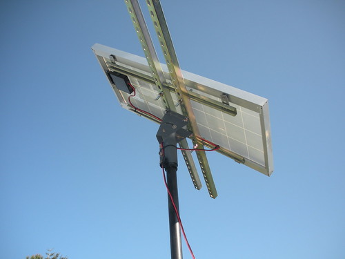
-
Re: DIY battery monitor/charger
Found some good info about charge efficiency while researching run-time routines for my software. I'm sure it's old news to the pros, but it's new to me.
http://www.sandia.gov/pv/docs/PDF/batpapsteve.pdf
http://photovoltaics.sandia.gov/puborder.htm
http://photovoltaics.sandia.gov/
http://ecee.colorado.edu/~ecen4517/materials/Battery.pdf
http://www.thermoanalytics.com/docs/batteries.html -
Re: DIY battery monitor/charger
After working in rain for 2 months, it's finally above 80 here. Took some photos of the system in operation powering the sun-room outdoors. Flickr slideshow. http://www.flickr.com/photos/nsaspook/sets/72157622934371746/show/
Dual inverter power monitor screen. Battery 1 running inverter in float charge mode.
Line 2: PV input voltage CC output voltage, charge current.
Lines 3&4: battery 1/2 voltage,run time at current usage, soc, Ah used.
http://farm5.static.flickr.com/4022/4693984527_02e56de9e5_b.jpg
Analog meters for PV input.
http://farm5.static.flickr.com/4029/4693983987_3569f2a4d1.jpg
Solar arrays: Unistrut and old Sat dish mount.
http://farm5.static.flickr.com/4025/4694617830_536114087c_b.jpg
Old TV with dtv converter box, cheapo am/fm cd player and cooling fan.
http://farm5.static.flickr.com/4064/4693983193_73d44566c6.jpg
C18 source code: Still under development but mostly working.
http://mysite.ncnetwork.net/res02dad/sitebuildercontent/sitebuilderfiles/swm8722.zip -
Re: DIY battery monitor/charger
So many relays and diodes. Schematic is hard to see.
You want to keep away from high current relays if you have them in battery path. You will take up a lot of battery power just on relay coils. Diode drops even in measurement path will have a temp dependancy.
You can put shunt in each battery leg to get current through each parallel path.
Ideally you want to 'snap shot' every current shunt and battery voltage at same instant. Your inverters battery supply lines is not pure, even, D.C. current. For sinewave inverters the current profile looks like a full wave rectified sinewave. For modified sinewave it is pulses of current. This is why it should be snap shot so all currents and voltage are from same instant in time. If you do this fast enough you can compute series resistance of batteries which is a good indicator of battery health.
One way to snap shot is low current relays to put a cap across measurement. Then flip caps over to ADC and round robin the reading on all the charged caps. With very high impedance input on ADC there is negligable voltage drop for the cap voltage storage from point of measurement to actual ADC reading. ADC in PIC is a successive approximation so it takes some time to make measurement. Cap tranfer reading can also solve voltage offsets when dealing with batteries stacked in series. The capacitor transfer relays can be replaced with small signal MOSFET's. This is how the Hybrid vehicles deal with series connected batteries producing over 300 vdc.
You can average things out with R-C filters if that is all you want. -
Re: DIY battery monitor/chargerSo many relays and diodes. Schematic is hard to see.
You want to keep away from high current relays if you have them in battery path. You will take up a lot of battery power just on relay coils. Diode drops even in measurement path will have a temp dependancy.
You can put shunt in each battery leg to get current through each parallel path.
Ideally you want to 'snap shot' every current shunt and battery voltage at same instant. Your inverters battery supply lines is not pure, even, D.C. current. For sinewave inverters the current profile looks like a full wave rectified sinewave. For modified sinewave it is pulses of current. This is why it should be snap shot so all currents and voltage are from same instant in time. If you do this fast enough you can compute series resistance of batteries which is a good indicator of battery health.
One way to snap shot is low current relays to put a cap across measurement. Then flip caps over to ADC and round robin the reading on all the charged caps. With very high impedance input on ADC there is negligable voltage drop for the cap voltage storage from point of measurement to actual ADC reading. ADC in PIC is a successive approximation so it takes some time to make measurement. Cap tranfer reading can also solve voltage offsets when dealing with batteries stacked in series. The capacitor transfer relays can be replaced with small signal MOSFET's. This is how the Hybrid vehicles deal with series connected batteries producing over 300 vdc.
You can average things out with R-C filters if that is all you want.
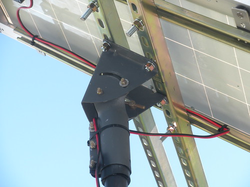
What can I say, you really have no idea what my design is doing. (Totally my fault for not updating the poor early drawings) I don't use shunts at all, mine are all hall effect transducers. Each ADC input has it's own pin on the chip so no need for measurement relays meaning all (real-time) measurement are within few ms of each other. I digitally average and low-pass the currents to remove inverter/charge controller measurement artifacts. The diodes are to isolate the 4 batteries (quad redundancy) powering the PIC controller 12 to 5vdc regulators. The total controller current under use or in charge is under 400ma (150ma when idle mainly from a old LED voltage module) because I designed the relay logic paths to be de-energized during normal operation. -
Re: DIY battery monitor/charger
If that is still the old Trace C40 design it is not hard to decode the signal from the RJ connector. It is biphase TTL, sending 22 bytes every second of the various voltages, setpoints, and the current in half-amp steps. Google c40out.gif to find it in the old usenet faq.It's using a Xantrex C40 for the solar charge controller -
Re: DIY battery monitor/chargerIf that is still the old Trace C40 design it is not hard to decode the signal from the RJ connector. It is biphase TTL, sending 22 bytes every second of the various voltages, setpoints, and the current in half-amp steps. Google c40out.gif to find it in the old usenet faq.
I finally decoded some of it but decided to only use the LED signal to detect the C40 charging state. My Hall sensors and the pic18 adc inputs have much better performance than the crude data displayed by the charge controller.
I'm using "Eagle Cad" to input the total wiring diagram and to design a PCB to replace the breadboard design. It's changed a lot since the start. (That's my lame reason for never updating the original one)
The reason for so many relays.
1. Cheap, I already had them in my junk box and have total isolation from switching transients. (important for stable controller operation)
2. The PIC control relays use only 25mA/5vdc but can switch 10A at 15vdc and drive 40A/200A latching relays that are mainly off for normal operation.
3. I am monitoring the SOC and charging of 4 batteries , so I need to isolate the picked battery from the controller, then disconnect the C40 PV input , disconnect the C40 battery load to reset the CC and reconnect the picked battery/PV make it do a full charge cycle on the battery if needed. If the C40 is in float mode I just disconnect the PV input and switch batteries, always leaving one connected to keep it running float mode. -
Re: DIY battery monitor/charger
Moved the project files to google code for public access. Things are working pretty good but as usual I need more panels to run the AC in this heat.
http://code.google.com/p/solar-monitor/
Data plot from system SD card data using Open-Office calc.
http://solar-monitor.googlecode.com/files/ac_usage.pdf -
Re: DIY battery monitor/charger MBMC
Multi Battery Monitor Charger
Software updated on http://code.google.com/p/solar-monitor/ -
Re: DIY battery monitor/charger
Nice mount and great BM system with Hall effect sensors.
Where did you get the frame and track? I have a bunch of sat dish mount that I'd to retrofit 2 panels. Thanks. -
Re: DIY battery monitor/chargerNice mount and great BM system with Hall effect sensors.
Where did you get the frame and track? I have a bunch of sat dish mount that I'd to retrofit 2 panels. Thanks.
It's a Unistrut homebrew. That pipe is Schedule 80 304/304L (stupid strong) from a high pressure system we scrapped at work.
Big images:
http://www.flickr.com/photos/nsaspook/5579954060/sizes/o/in/photostream/
http://www.flickr.com/photos/nsaspook/5579368597/sizes/o/in/photostream/
If you use a dish mount be sure it's for a larger KU 1M+ size or C band type mount. The mounts for most home sized dishes are too weak.
Here is the current debug/status display on the BM via the RS232 port on the PIC18F8722 microcontroller.
(PV History reset yesterday due to software changes)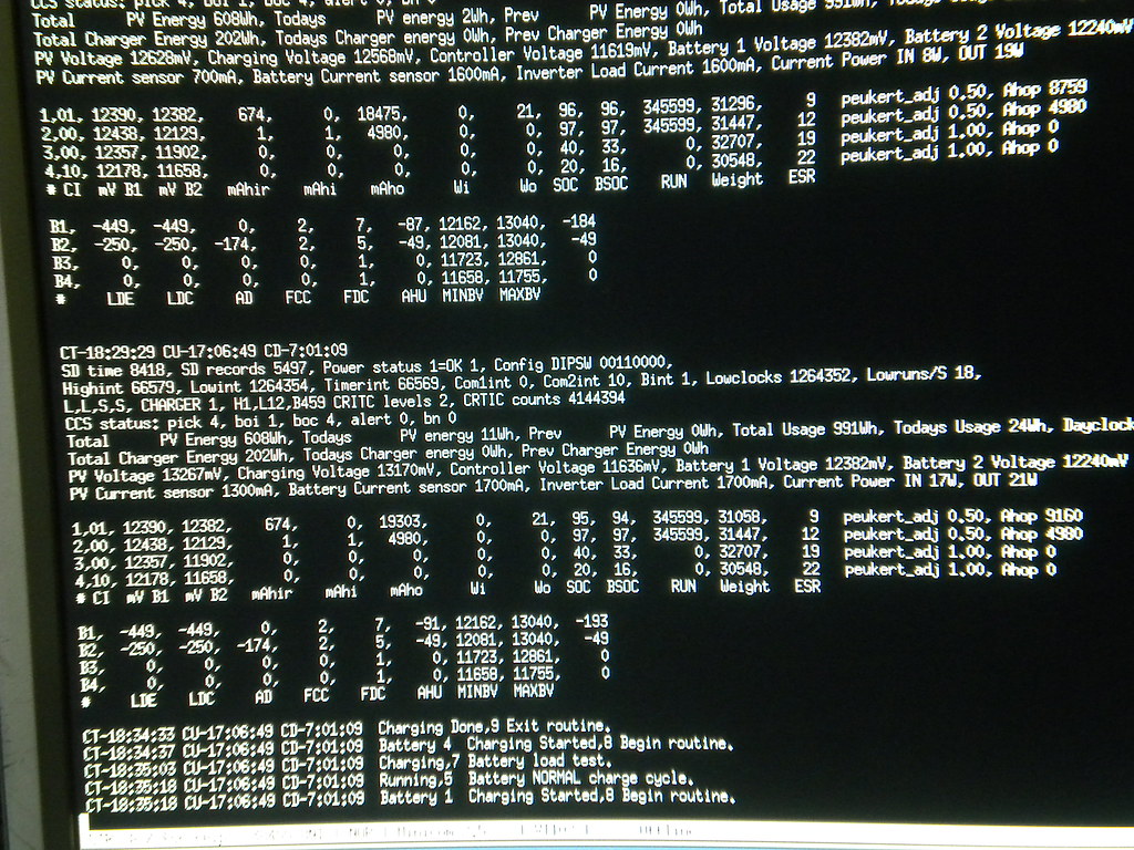
The main software in pretty compete in function but now I need to add a slave module to interface with a home-automation system running on Linux. -
Re: DIY battery monitor/charger
Nice BM, any chance of incorporating ethernet or wifi for remote and data acquistion? Webserver functionality would be nice as well.
Saw your impressive clean and neat setup on flickr. How does the hall effect sensor wire on to the battery system? pics. -
Re: DIY battery monitor/chargerNice BM, any chance of incorporating ethernet or wifi for remote and data acquistion? Webserver functionality would be nice as well.
Saw your impressive clean and neat setup on flickr. How does the hall effect sensor wire on to the battery system? pics.
The current plan to to feed the data from the other RS-232 port to a Linux server that will log it into a mysql database for later processing. I'm getting close to the max on what a single 8 bit PIC chip can handle with limited memory and ports.
The system uses two current sensors because I need to be able to both charge and use different batteries at the same time while still keeping track off everything. The open-loop sensors work well but I'm thinking about a redesign using closed-loop models to reduce drift over time.
PV current sensor: http://farm6.static.flickr.com/5268/5584313002_f4c3c39d22.jpg
Battery sensor: http://farm6.static.flickr.com/5174/5584313284_ecafb1abec.jpg
Battery sensor on battery ground return wire to monitor current: http://farm6.static.flickr.com/5065/5584312830_184213a919.jpg
The PERCO switch has a small roller-switch on the knob that sends a signal to the controller about what battery is supplying current to the inverter.
The run-time data for loads is displayed on the front LCD panel.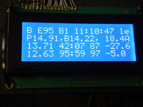
Line 1: Bulk mode, Efficiency of charge controller, Battery number, Max time if not fully charged.
Line 2: Voltage from PV, Voltage to battery, Charge current.
Line 3: Battery 1 voltage, Run-time at current load, State Of Charge, Ah used
Line 4: Data for Battery 2.
Below is a simple diagram of where the sensors are in the circuit. (I'm not an artist) -
Re: DIY battery monitor/charger
Now that the solar controller code is pretty stable, it's time to work on the host controller.
I'm using a PIC32 Ethernet demo board and i/o expander to talk to the controller for control and status using the web server. The Microchip demo app is being modified to use a rs-232 port for the data link. It's mostly just a mockup for now until I build a interface card for the PIC32 using a MAX235 chip on a PICtail prototype board.
http://www.flickr.com/photos/nsaspook/5616650161/
http://www.flickr.com/photos/nsaspook/5617235826/
http://www.flickr.com/photos/nsaspook/5616674221/ -
Re: DIY battery monitor/charger
Awesome work here, please keep us updated!!:-)
TBR -
Re: DIY battery monitor/charger
Basic networking is running using a simple master/slave comm protocol that can transfer binary blobs (C data structures) directly from one processor to the other.
The PIC32 is running a test program that just moves the data for now so I can add CRC checks and cleanup the network code.
Short video: http://flic.kr/p/9z7hYU
PIC32 test code link: http://solar-monitor.googlecode.com/files/uart_interrupt.zip
It's just a modded version of the uart demo. The structure types have to be defined with variable types that both the PIC18 and PIC32 C versions know the exact size of in mbmc.h -
Re: DIY battery monitor/charger
Ethernet, now we are talking.
Racks of electronics. Way easier to hook them up than to take them down to troublshoot. Impressive as usual. Keep us posted. -
Re: DIY battery monitor/chargerBasic networking is running using a simple master/slave comm protocol that can transfer binary blobs (C data structures) directly from one processor to the other.
The PIC32 is running a test program that just moves the data for now so I can add CRC checks and cleanup the network code.
Short video: http://flic.kr/p/9z7hYU
PIC32 test code link: http://solar-monitor.googlecode.com/files/uart_interrupt.zip
It's just a modded version of the uart demo. The structure types have to be defined with variable types that both the PIC18 and PIC32 C versions know the exact size of in mbmc.h
VERY impressive ! You've done a LOT of work !
Went to your WWW... I really appreciate the old fart and geek projects. We are a dying breed I'm afraid, for example, looking at your old hand wired video controller.
I've also taken the Coast Starlight about 20+ years ago ! What a GREAT trip !
boB -
Re: DIY battery monitor/charger
I've finished the basic PIC18/PIC32 serial network drivers /API and coded most of the basic callback functions for the web server on the Microchip TCPIP stack app.
The only real problem was getting the structure defines and alignments correct for both controllers. The PIC32 wants data on 4 byte hunks but the PIC18 packs structures to 1 byte. A few tricks with the GCC __attribute__ pragma fixed that.
Short Video: http://flic.kr/p/9ALee7
Code link for these who care to look.
http://code.google.com/p/solar-monitor/downloads/list -
Re: DIY battery monitor/charger
Well, most of the fun stuff is done. The basic model for two way comms and control of the system from the web host, near real-time system status on the web and javascript generated charts from data cached on the host database collected from the controller. Next is the boring part of creating all the web pages, writing the chart functions and finding the bugs in software.
Short Video: http://flic.kr/p/9D79E2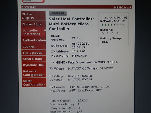
WebFX has a great free chart/graph system in Javascript.
http://webfx.eae.net/dhtml/chart/chart.html -
Re: DIY battery monitor/charger
Some energy charts from the solar monitor web server for a few days. Saved in .mth format in the zip file. The power units are in watt-hours.
http://mysite.ncnetwork.net/res02dad/sitebuildercontent/sitebuilderfiles/mbmccharts1.zip -
Re: DIY battery monitor/charger
Solar monitor source code home. http://code.google.com/p/solar-monitor/ -
Back again as a new user (lost old password)
My current DIY monitor control project with a FM80 custom controller is here.
https://forum.allaboutcircuits.com/threads/fm80-solar-charge-controller-datalogger.194146/post-1825897
It uses a custom PIC18 controller board to talk to the FM80 communications port and HTTP and MQTT services
on another PIC18 controller and a Linux server power controller and optimizer. -
Welcome back NSASpook.
Nice looking project and results.
-BillNear San Francisco California: 3.5kWatt Grid Tied Solar power system+small backup genset -
Thanks, good to be back. The Home Assistant integration with solar is great but it can't handle complex power controls in near-real time like dedicated hardware and software resources can.BB. said:Welcome back NSASpook.
Nice looking project and results.
-Bill
It's basically a solar hybrid battery bank, power shifting system. The Linux server program monitors all system parameters and optimizes day GTI outputs while allotting solar energy to keep the main battery LiFePO4 5120Wh battery full while using the secondary 5120Wh AGM (several years old) battery bank as an excess energy dumpload to supply house power loads.
It's a retirement (well almost retired) project.
My original DIY solar project is still running.


Categories
- All Categories
- 233 Forum & Website
- 140 Solar Forum News and Announcements
- 1.3K Solar News, Reviews, & Product Announcements
- 181 Solar Information links & sources, event announcements
- 895 Solar Product Reviews & Opinions
- 252 Solar Skeptics, Hype, & Scams Corner
- 22.5K Solar Electric Power, Wind Power & Balance of System
- 3.5K General Solar Power Topics
- 6.7K Solar Beginners Corner
- 1K PV Installers Forum - NEC, Wiring, Installation
- 2.1K Advanced Solar Electric Technical Forum
- 5.6K Off Grid Solar & Battery Systems
- 428 Caravan, Recreational Vehicle, and Marine Power Systems
- 1.1K Grid Tie and Grid Interactive Systems
- 656 Solar Water Pumping
- 816 Wind Power Generation
- 621 Energy Use & Conservation
- 623 Discussion Forums/Café
- 316 In the Weeds--Member's Choice
- 74 Construction
- 125 New Battery Technologies
- 108 Old Battery Tech Discussions
- 3.8K Solar News - Automatic Feed
- 3.8K Solar Energy News RSS Feed