Project: Designing Solar Meter

System
Posts: 2,511 admin
Hey all,
I've been looking into alt energy for some time now (yourgreendream, instructables, various other sites) and looking through various books (Alternative Energy Handbook, etc).
Anyhow, I'm a senior Electrical Engineering student who has a team together for a project class, and we're strongly considering making a combined solar charge controller and battery bank monitoring system with inbuilt logging and control features, so you could see how much solar you've collected over the past month, how much energy your home consumes on a day by day basis, etc.
We are considering other ideas, like being able to have the device sense when the battery bank is low and switching to grid power (trying to avoid grid-tie with this, but might be worth doing if I could find out more about it).
If there is anything you think might be particularly useful or interesting to see, let me know. If we end up doing this I plan on posting the steps, materials, etc for others to use as a learning tool. Just trying to bring solar to a wider audience") .
.
Also, if this seems like a silly or terrible idea, feel free to let me know as well. I figured I'd post here since you guys seem to be experts on the subject.
I've been looking into alt energy for some time now (yourgreendream, instructables, various other sites) and looking through various books (Alternative Energy Handbook, etc).
Anyhow, I'm a senior Electrical Engineering student who has a team together for a project class, and we're strongly considering making a combined solar charge controller and battery bank monitoring system with inbuilt logging and control features, so you could see how much solar you've collected over the past month, how much energy your home consumes on a day by day basis, etc.
We are considering other ideas, like being able to have the device sense when the battery bank is low and switching to grid power (trying to avoid grid-tie with this, but might be worth doing if I could find out more about it).
If there is anything you think might be particularly useful or interesting to see, let me know. If we end up doing this I plan on posting the steps, materials, etc for others to use as a learning tool. Just trying to bring solar to a wider audience
Also, if this seems like a silly or terrible idea, feel free to let me know as well. I figured I'd post here since you guys seem to be experts on the subject.
Comments
-
Re: Project: Designing Solar Meter
For battery based systems, a load controler with setable on off voltage levels would be nice, This would aid in off grid systems being more effiecent. Rather than burning off the excess current, running a heater or AC after batteries have been topped of would allow the use of this "extra" power.
In off grid situations we want to start a generator rather than switch to grid power, since if your already connected to the grid why have batteries.Home system 4000 watt (Evergreen) array standing, with 2 Midnite Classic Lites, Midnite E-panel, Magnum MS4024, Prosine 1800(now backup) and Exeltech 1100(former backup...lol), 660 ah 24v Forklift battery(now 10 years old). Off grid for 20 years (if I include 8 months on a bicycle).
- Assorted other systems, pieces and to many panels in the closet to not do more projects. -
Re: Project: IDEAS for Designing Solar Meter
JJ, from my perspective, as the Midnight Solar Classic is attempting to do, a CC and monitoring system needs to be :
usable ON and OFF grid,
be old tech friendly as well as up to date (reverse compliant),
does not require add-ons to read/transfer data (ie OB MATE)
and possibly be remote monitored if on the Net,
or will store more than 60 days worth of summary data ie > = sum of Kwh
ie you can set the time period for data collection eg 30 minutes... during the day
for southern folk that have trackers maybe a tracking initiation circuit based on a low level of watts relative to the array rating considering the time of day/ sun elevation?
all pie in the sky or are they?
Versatility is the key.8)
I am sure that others here can give you more different things they might like to see... Tally Ho...
cheers
Eric
KID #51B 4s 140W to 24V 900Ah C&D AGM
CL#29032 FW 2126/ 2073/ 2133 175A E-Panel WBjr, 3 x 4s 140W to 24V 900Ah C&D AGM
Cotek ST1500W 24V Inverter,OmniCharge 3024,
2 x Cisco WRT54GL i/c DD-WRT Rtr & Bridge,
Eu3/2/1000i Gens, 1680W & E-Panel/WBjr to come, CL #647 asleep
West Chilcotin, BC, Canada -
Re: Project: Designing Solar Meter
How far (technically) do you want to take this project... It can be a big one to tackle.
Sol,ar Guppy has recommended this paper (from this thread) on MPPT controller design:
Mppt Thesis Hannes Knopf 1999
That would be a good project in itself. The Battery/Load Monitor is probably a separate design project (although they could be integrated to a single controller).
-BillNear San Francisco California: 3.5kWatt Grid Tied Solar power system+small backup genset -
Re: Project: Designing Solar Meter
Well I am hardly the most technically informed or inclined member here, but having lived off grid for many years and struggling through the learning curve of battery charging and load managing I would say that making one unit that would have more control or "awareness" of the system as a whole would be very helpful. I agree completely with the suggestions from Photowit and Westbranch on helpful features.
One similar feature that I would find very useful would be the ability of the charge controller to sense how much of it's output is actually going into the batteries versus other loads. Then you could make much better use of an "end amps" function to switch the charging mode from Absorb to Float. My MX-60 has this feature, which works fairly well if no one is home using any power during the day, but if anyone is using any power then the charger thinks that it's putting all of this into the batteries and thus wont switch to float without a manual override.
Being a mostly non technical sort, I have no idea what it would take to accomplish any of these things. As Bill pointed out, you might be in for one whale of a project to fit in all the features that us off the grid folks would want (I have no sense of what on grid battery back up systems might want). I sure like the idea of some sort of a central unit that had the ability to not just monitor, but also to manage more of the system (better generator/pv charging, load management, clear communication throughout the system).
Let us know what becomes of this project.
HB -
Re: Project: Designing Solar Meter
One other possible suggestion... Poster "lorelec" here makes/sells a 30 amp MPPT controller Rogue MPT-3024 and at one time (if I recall correctly) he used to sell controller kits and schematics for do-it-yourself projects.
He does not offer the kits on his website at this time--but it might worth contacting Marc and see if you guys can work something out.
-BillNear San Francisco California: 3.5kWatt Grid Tied Solar power system+small backup genset -
Re: Project: Designing Solar MeterHe does not offer the kits on his website at this time--but it might worth contacting Marc and see if you guys and work something out.
-Bill
I decided to discontinue kits/plans for various reasons...mostly because it became clear that the kits were too difficult for many homebrew builders to assemble.
Marc -
Re: Project: Designing Solar Meter
Thanks for the input so far everyone, its really great. I am meeting with some professors this week to find an advisor for the project, and still fleshing out how deep we want to go with this thing. The MPPT seems fairly large in itself, but there seem to be a few schematics floating about (http://www.onsemi.com/pub_link/Collateral/DN06054.PDF , http://archive.electronicdesign.com/files/29/6262/figure_01.gif ). Lorelec, based on what you said about the difficulty of making them I might end up buying one, but we'll see what happens.
The chip we will likely use for the "brains" of this whole operation is an Altera Cyclone II, I don't know much more beyond that, but the FPGA guy on our team said that would be something he thinks he has access to. I'm hoping we can use it to store data logs. He seems interested in making a VGA out for a small, low-power display to show the data, I don't know if thats preferable to feeding it out via another method (USB-drive accessible as text file, scrolling LED display, etc).
As for the data to monitor, maybe it makes the most sense to monitor the current flowing out to the inverter, and the current flowing into the battery. The sum of these two currents should equal the output of the charge controller.
Since the voltage is locked at 12V on that side of the circuit, I could calculate power based on those current measurements, and would be able to give net totals of wattage to the inverter and wattage to the batteries over a period of time.
It sounds like having summary data over a long period of time is a useful function, and perhaps day by day information for a month or two would be good as well.
Still thinking and looking, but definitely enjoying all the help/comments/advice - looking through that MPPT paper now actually, thanks for that! -
Re: Project: Designing Solar Meter
Project Update:
We've solidified (somewhat) the plans with an advisor, and it looks like the following:
A solar charge controller with data logging and AMI intertie
MPPT Charge controlling (actually, found a very useful complete schematic and code for control doing this with an Arduino, for anyone interested, here - http://www.timnolan.com/index.php?page=arduino-ppt-solar-charger)
Data logging to SD Card, with a config file on the card that can be modified by the user to change logging intervals. This would also allow long term (60 days or more) monitoring.
Data input from AMI (Advanced Metering Infrastructure) that tells the current price of power from the utility, and takes this into account with other system parameters (current solar generation, current battery charge, and current/predicted home usage) to determine when to buy or sell power to the grid. In states with net metering (like Ohio, where we are) this means that we could charge the batteries with low cost power earlier in the day at a lower price, and potentially sell it back to the utility at peak hours at a higher price later in the day. We are only going to be simulating with AMI data, but the chip we are using (Arduino Mega) has serial inputs that would make it (presumably) pretty easy to implement actual AMI inputs in practice.
One technical question we are running against is this: If a lead-acid battery is partially discharged, how can you determine the remaining KWh in the battery? Take the nominal voltage multiplied by the "percent" remaining using a chart, or multiply the actual voltage multiplied by the "percent" remaining using a chart (the chart being one of those that tells you the battery voltage related to the remaining charge percent on the battery)?
Thanks again for the links and info, that Midnite Solar Classic looks really nice. -
Re: Project: Designing Solar Meter
As a first approximation, Lead Acid batteries are nearly 100% efficient in Amp*Hour in/out or "coulomb efficiency"... This relationship does break down when the battery is nearly fully charged and it starts electrolyzing water.
Battery-Powered Systems: Efficiency, Control, Economics (PDF)
So, the basics would look like: User programs in Battery Capacity (Amp*Hours) and measures Amp*Hours out (load) and Amp*Hours back in (charging). Reset when Battery is "Charged" (battery voltage high, and charging current low).
Then, you can take into account that a battery becomes less efficient as the current flow increases--The Peukert Effect.
Then, you can take battery temperature into account (battery capacity reduces as temperature drops).
And, you can add Watt*Hour estimates (take battery voltage into account).
And you can add monitoring as battery ages, the efficiency drops...
Lots of interesting stuff to followup on.
-Bill
Near San Francisco California: 3.5kWatt Grid Tied Solar power system+small backup genset -
Re: Project: Designing Solar Meter
Bill's being nice giving the factors, but basiclly an estimate is all you will ever get as these factors obviously effect each other as well, plate metalurgy, and sizing, acid stregnth/Chemistry also factor in...Home system 4000 watt (Evergreen) array standing, with 2 Midnite Classic Lites, Midnite E-panel, Magnum MS4024, Prosine 1800(now backup) and Exeltech 1100(former backup...lol), 660 ah 24v Forklift battery(now 10 years old). Off grid for 20 years (if I include 8 months on a bicycle).
- Assorted other systems, pieces and to many panels in the closet to not do more projects. -
Re: Project: Designing Solar Meter
I am designing a simple PIC micro-controller monitor for a small PV/battery system.
Here is a link to some pictures, video and current source code.
Build Video. http://www.flickr.com/photos/nsaspook/sets/72157622934371746/show/
Source code. http://forum.allaboutcircuits.com/attachment.php?attachmentid=17501&d=1269059776/* * This program controls and monitors solar power battery arrays * * * USART2 is the host comm port * USART1 charge controller port (NOT YET DONE) * Timer0 1 second clock * Timer1 background I/O clock * PORTA analog inputs * adc0 vbatol PIC Controller supply voltage to 5VDC regulator * adc1 solar Charging voltage at battery from CC * adc2 currentin 50A AMPLOC sensor input from PV array * adc3 rawp1/inputpower Voltage from PV array * adc4 rawp2/primarypower Voltage a primary inverter battery * PORTF analog inputs * adc5 current 300A AMPLOC sensor battery output to inverter * PORTD switch input * PORTE battery/charge relays * PORTJ load/input relays * PORTB external control i/o * PORTH0 run flasher led onboard. * 2x16 LCD status panel and led status lights. * * xxxxxxx@xxxxxx.com Copyright 2010 * Fairview, Oregon * * * This application is designed for use with the * ET-BASE PIC8722 board and LCD device. * * RS-232 host commands 9600baud 8n1 * A send controller/battery status * B select battery for modify commands, used with S M L * C (NOT DONE YET) * D V M L Calibrate ADC voltages, example DVMZ would adjust adc0 up 1 tick, DDDVLLZ would adjust adc2 down two ticks * THIS FUNCTION USES THE EEPROM WRITE DURING INTERRUPT (TOO MANY FAST KEYPRESSES WITH CAUSE A LOCKUP) * F Force current (none critical) charge routine to exit * K lockup controller causing WDT timer to reboot * S M L modify selected battery type, example: ZBBMZ would set battery 2 to M type. * Z reset command parser * ? controller attention needed/sent to host to request action (usually a status) * $ fuse blown error. (NOT DONE YET) *
It's messy but most prototypes are.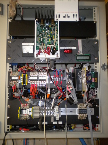


Categories
- All Categories
- 230 Forum & Website
- 137 Solar Forum News and Announcements
- 1.3K Solar News, Reviews, & Product Announcements
- 181 Solar Information links & sources, event announcements
- 892 Solar Product Reviews & Opinions
- 252 Solar Skeptics, Hype, & Scams Corner
- 22.5K Solar Electric Power, Wind Power & Balance of System
- 3.5K General Solar Power Topics
- 6.7K Solar Beginners Corner
- 1K PV Installers Forum - NEC, Wiring, Installation
- 2.1K Advanced Solar Electric Technical Forum
- 5.6K Off Grid Solar & Battery Systems
- 428 Caravan, Recreational Vehicle, and Marine Power Systems
- 1.1K Grid Tie and Grid Interactive Systems
- 656 Solar Water Pumping
- 816 Wind Power Generation
- 620 Energy Use & Conservation
- 623 Discussion Forums/Café
- 316 In the Weeds--Member's Choice
- 74 Construction
- 125 New Battery Technologies
- 108 Old Battery Tech Discussions
- 3.8K Solar News - Automatic Feed
- 3.8K Solar Energy News RSS Feed