Illustration of 8 KW (DC) GT Solar PV System Install for Residence in Urban Area
Comments
-
Re: Illustration of 8 KW (DC) GT Solar PV System Install for Residence in Urban Area
I have a substantial update coming, including pictures. Lots of good progress on many subjects.
I've learned a lot the past few weeks, from here and elsewhere. I hope to pass it along here, to the benefit of others for when they become first time GT-only solar PV system owners.
Living in a municipality that didn't have one solar PV installation 3 months ago, and now averages 1 - 2 solar PV installation permit requests per week has added to some of the complexities and challenges.
Best regards,
Bill -
Re: Illustration of 8 KW (DC) GT Solar PV System Install for Residence in Urban Area
The purpose of this continuing illustration is three-fold:- Help others, who want a solar PV system, either via DIY or professional installer, understand the design and installation details required, specific to a grid-tie-only system. (There's nothing here involving batteries.)
- Enhance my understanding of solar PV systems by chronicling an installation.
- Put together a first-attempt for future presentations I've already been asked to do here locally.
I've certainly gained appreciation this is a 600 volt system being installed into a residential structure. Something that in the past was reserved for commercial structures. Customers, installers, product makers, the NEC and other regulatory bodies, municipalities, and even elected representatives are all going through a learning curve at this time to enhance the residential solar PV market while simultaneously attempting to maximize safety to residential building occupants (who may be purchasers of a residence with solar PV already present).
The fact that a 600 volt system may now exist in a residence certainly affects emergency responders too - something they haven't had to generally be concerned about, when going to a residence, until now.
And I've gained a lot of appreciation that solar PV installations are permanent to the structure (when panels are roof mounted). While solar panel warranties 'only' go out 20 years, typically these are to ensure 80% performance, and that in fact it's not unreasonable to expect panels to perform for 30 to 40 years out.
It's a lot more obvious now that permanent to the structure includes roof penetrations and associated risks of water infiltration. If there's one thing I would do differently if I had this project to do over is to better understand, pre-contract signing, details of roof penetrations, and to make sure all involved were in agreement as to technique and materials to be used associated with the penetrations.
A final summary comment is grounding strategy is a remaining subject area I have question about. I posted, outside of this thread, questions on shading impact to panels, appropriate junction boxes for external use, wire management, etc. I very much appreciated the assistance. After I get caught up here, I've got some grounding strategy questions that I'll post separately.
Next: contract description error.
Best regards,
Bill -
Re: Illustration of 8 KW (DC) GT Solar PV System Install for Residence in Urban Area
OK, at the time of the last update, a lot was happening. Here I'll catch up on some attention that was occurring specific to my contract.
A key item, that caused my installer to post here (earlier), was my inaccurate posting of my purchase details. I failed to appreciate the importance to accurately state, in response to some early-thread questions, terms of my purchase, leading some to conclude that perhaps my installer was doing a 'lease the rooftop' installation, which is prohibited by Texas state law (but not so in other states).
In fact, a report was made to either the Texas Public Utilities Commission, or a representative, causing some unfortunate intensity for my installer.
There are two pieces of my contract that are critically important to emphasize whenever I chat about details.- My contract is clearly a 'lease purchase,' not a 'lease.' After 10 years, I have the option to purchase the system.
- Secondly (and something I didn't know at the time), the purchase option price is adjusted annually to reflect whatever monthly payment changes are made throughout the contract. (Recall that I'm guaranteed that my fixed monthly payment will be a savings of at least 30% of my kWh cost from my electric utility provider.)
Next: solar PV design looked at further, and changed.
Best regards,
Bill -
Re: Illustration of 8 KW (DC) GT Solar PV System Install for Residence in Urban Area
Here's an update on the solar PV system design.
If it was just roof surface area to determine max system size, I've got plenty of area to easily accommodate a 10 KW (DC) system (max allowed by TX utility incentives).
As it turns out, though, the design is fairly challenging to maximize harvest amount, and 8 KW is about the most that can be accommodated.
The challenges include shading from projections above the roof (i.e. a chimney, wind turbines, plumbing stacks, etc.), shading from nearby trees, two different panel orientations, and less than ideal azimuths for the orientations. Tilt (at 35°) is the only non-changeable design factor that is ideal.
A little less than 30 panels could be squeezed in on the roof area over the house, at an azimuth of 210°. Perhaps 15 can additionally be put on the roof area over the garage, at an azimuth of 285°.
Shading and aesthetics limit the number of panels on the house to 27, though. On the garage shading limits the number of panels to 9.
The fundamental design question is how to economically maximize the harvest from these 36 panels.
As of the last posting regarding design, the plan was to put 2 strings of 13 panels each (225 W DC) on the already installed SunnyBoy 7000 inverter, move 1 panel from the house to the garage roof, connect the 10 garage panels as a single string to another yet-to-be-purchased/installed SunnyBoy 3000 inverter, combine the 2 inverter ouputs to a new-to-be-installed service sub panel (no room in the existing service panel), and install a 'hot-tap' connection to the structure's electric service (max circuit breaker size is 40 A for my 200 A panel, a breaker size not large enough to accommodate the output sum of 2 inverters).
This design preserved the basic tenant that panels of one orientation shouldn't be mixed with panels of another orientation into a common inverter.
The problems here are two-fold:- Substantial underutilization of each inverter.
- Considerable additional expense for purchase/installation of another inverter, sub panel, and 'hot tap,' vs. harvest benefit.
So, the design going forward is a 3 x 12 system. Two strings of 12 panels each will be on the house roof (210° azimuth), and a 3rd string will consist of 3 remaining house panels with the 9 garage roof panels (285°).
This is an economics reality design, and acknowledges 2 shortcomings up front:- Strings of 2 different orientations will be combined into one inverter.
- For 1 of the 3 strings, panels of 2 different orientations will be combined into the string.
Here's an article titled Fronius IG Reaction to Non Optimal Conditions that discusses doing something like this design. Summary is:
"Good system design is a critical component in obtaining the maximum amount of energy (kWh) out of a PV system. However, non-optimal site conditions will often dictate that a system will lose a percentage of its typical output. These conditions fall into three general categories: shading, similar strings in parallel at different orientations, and dissimilar strings in parallel."It is hoped to see similar performance from my installed SunnyBoy 7000.
"This paper explains the FRONIUS IG’s reaction to each of the above conditions. Although module and site conditions vary, these results should be similarly exhibited in most cases with similar design issues. For most typical, non-optimal situations encountered in the field, the FRONIUS IG is able to still output within 99% of the total available energy."
PVWatts Ver 2, for my specific location cell (0218386) reports an average insolation for the year of 5.33 kWh/m2/day, accounting for historical weather patterns, cloudiness and temperature affect on the panels, assuming zero shade at any time, and assuming all panels are installed at ideal azimuth (180°) and tilt (latitude: 33.156°). With 36 panels, 225 W each, for an 8.1 KW system, PVWatts estimates theoretical annual production at 11.1 kWh.
Next keeping everything the same, but changing to my actual tilt (35°), PVWatts estimates theoretical annual production still at 11.1 kWh. So my actual roof tilt remains close enough to ideal to not affect the estimated harvest.
Next putting in 27 panels at 215°, and 9 panels at 285°, and all at 35° tilt, with all of the remaining givens noted above, PVWatts estimates theoretical annual production reduced to 10.2 kWh.
The summary here is the actual roof orientations, versus ideal, result in an 8% decreased harvest.
What I don't know how to do is estimate possible further impact on harvest due to a one-inverter for all, versus an inverter-per-orientation design. It is hoped that the Fronius research is equally applicable to today's SunnyBoy inverters.
Next: An Installation Change
Best regards,
Bill -
Re: Illustration of 8 KW (DC) GT Solar PV System Install for Residence in Urban Area
Here's a pictorial shade analysis summary. These were shot every 30 minutes, starting at 8 AM, on 12/09-10, eleven days before Dec. 21st, shortest day of the year.
House (215 degree azimuth, 35 degree tilt) roof panels:
Full sun by 10:30 AM except for chimney on one panel.
Light shade on 1 panel at 3:00 PM.
Shade moves gradually in at 3:30 PM.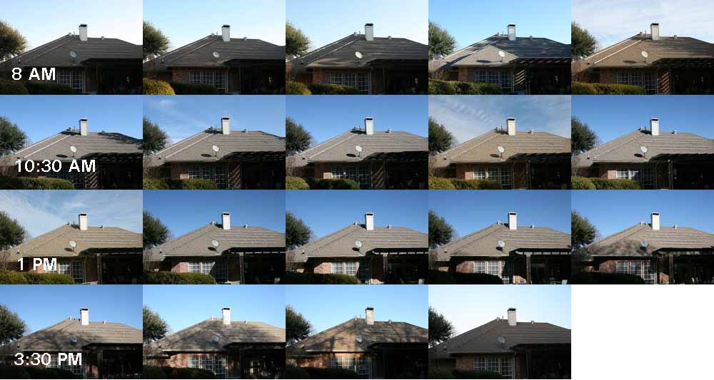
Garage (285 degree azimuth, 35 degree tilt) roof panels:
Full sun by 11 AM.
Shade starts at 2:30 PM on a panel.
Shade moves in at 3 PM.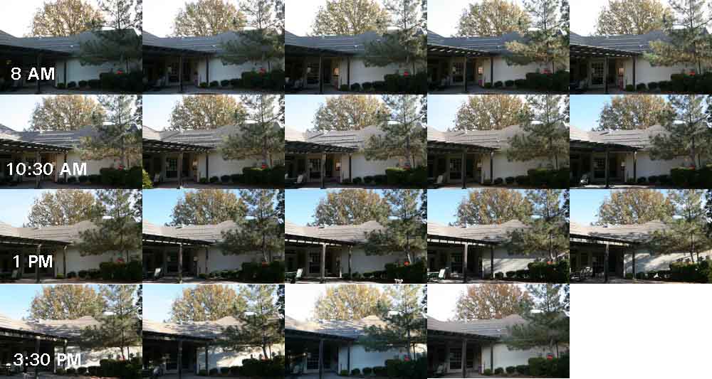
Best regards,
Bill -
Re: Illustration of 8 KW (DC) GT Solar PV System Install for Residence in Urban Area
The Fronius white paper is not measured performance, it is one persons interpretation of performance and we have no documentation to support the conclusions.
Based on my real life testing, I would offer an opinion
1) Fronuis paper is worthless , its a sales tool, nothing more.
2) Your never going to get only a 8% loss using a single vs dual inverters in your installation, your shading I would classify as severe. It will be much worse, 25% minimum. if you attempt to use a single inverter for all 3 strings.
3) I would even go as far to say your roof should use the Enphase inverters as the shading is so bad and random that I would be very surprised if you hit 60% of the PVWatts expected performance of a non-shaded array
I find it interesting, that with all the effort you put into this your final conclusion was adding an inverter was to expensive ... your talking about 2500 dollars in material costs, I suspect your installer helped in this thinking as its HIS money, not yours
Look forward to actual performance data once the system is commissioned -
Re: Illustration of 8 KW (DC) GT Solar PV System Install for Residence in Urban AreaSolar Guppy wrote: »... Your never going to get only a 8% loss using a single vs dual inverters in your installation, your shading I would classify as severe. It will be much worse, 25% minimum. if you attempt to use a single inverter for all 3 strings.
SG, much appreciate the comments.
My beginning list of additional loss contributors to kWh production, beyond the ones PVWatts assumes for it's default 77% factor, includes:- Panels not at 180° azimuth = -8%
- Shading = ?%
- Single inverter handling of strings of 2 different azimuths (210° and 285°) = ?%
- Inverter handling of a string with panels in 2 different azimuths = ?%
Best regards,
Bill -
Re: Illustration of 8 KW (DC) GT Solar PV System Install for Residence in Urban Area
Returning to the junction box subject.
I asked the installer to consider changing the 2 on-the-roof junction boxes from 'Wet Location' Bell switch boxes to something that is at least NEMA 4 rated, and to use roofing sealant.
The installer readily agreed.
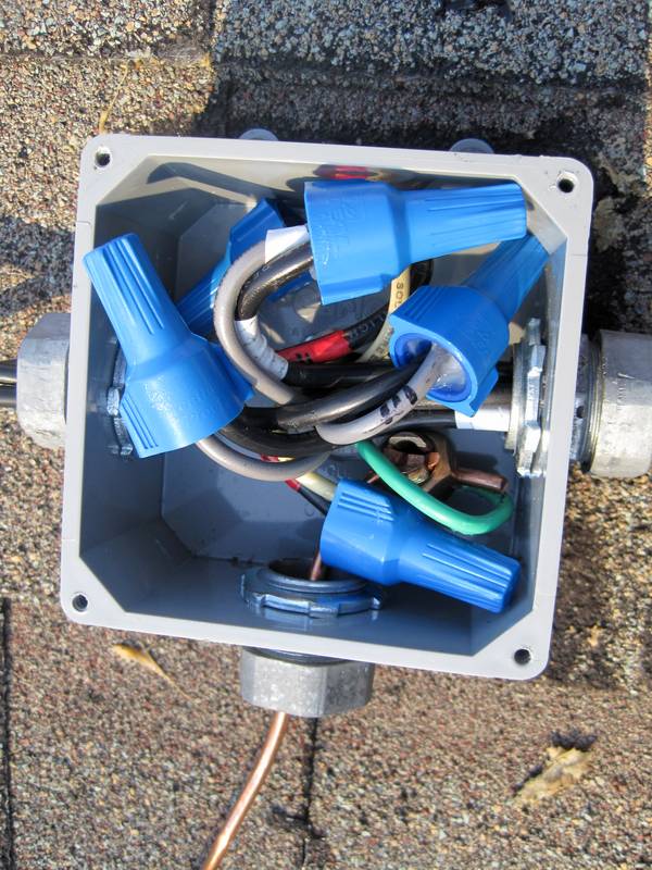
Below are a couple of images (shot 4:30 PM Central) of what was used. The boxes are Carlon molded nonmetallic. They are UL Listed and maintain a NEMA Type 6P Rating (ice) and Type 4/4X Rating. Screws are stainless steel. The boxes are 4x4x2", Model E987NNJ.
These junction boxes require field installed holes for fittings.
The boxes will not be exposed to UV as the panels will be on top of them.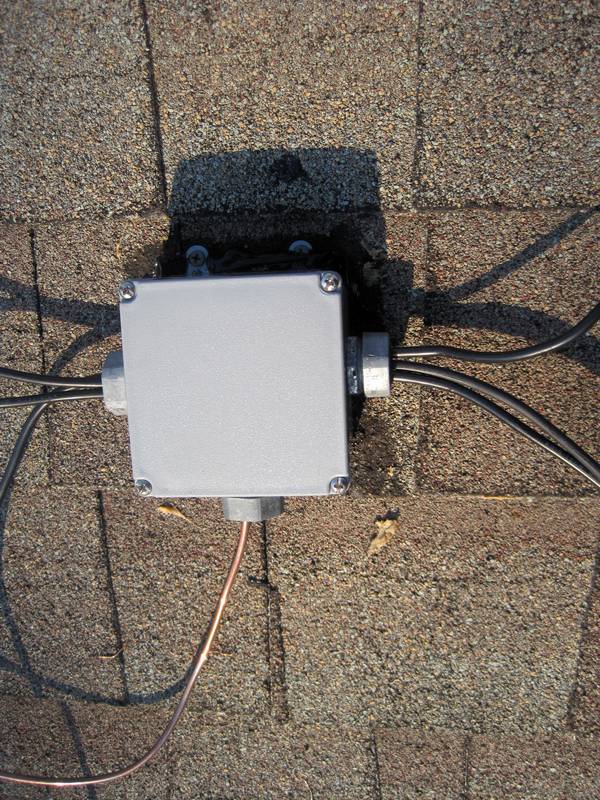
Next: Municipality requested installation changes.
Best regards,
Bill -
Re: Illustration of 8 KW (DC) GT Solar PV System Install for Residence in Urban Area
Not to pick nits, but in the interest in a trouble free install. I'm still not thrilled with the water seal (or lack thereof). This is a box that is going to sit in the elements for many years, and when it leaks, it will be under the panels.
I also would be concerned with the strain on the wire nuts. I think I would prefer some other mechanical connection, especially since these boxes will be under the Pv.
Tony -
Re: Illustration of 8 KW (DC) GT Solar PV System Install for Residence in Urban Area
OK. Moving now to a municipality requirement.
My City requires "Direct Current ungrounded conductors shall be Orange, Yellow or Brown. The grounded conductor shall be identified by the color Gray."
This requirement necessitated replacement of the DC THWN-2 wires, which were black for the ungrounded conductor and white for the grounded conductor.
Since the wire had to be replaced, the wire nut connections for the DC wiring were also eliminated in the interior attic pull box. Now, each string's DC wiring travels without any splices or wire nut connections, from the outside on-the-roof junction boxes direct to the inverter's DC Disconnect Switch.
Below is a picture of the new wires in the interior attic pull box - 3 strings travel to the left, consisting of 3 yellow and 3 gray wires, terminating at the DC Disconnect Switch.
Because 3 panels on the house roof are being combined with all 9 panels on the garage roof to form the 3rd string, a USE-2 wire for this string travels through the same interior EMT conduit. It's visible near the bottom right corner of the pull box. This avoids an unsightly external-to-the-roof conduit run.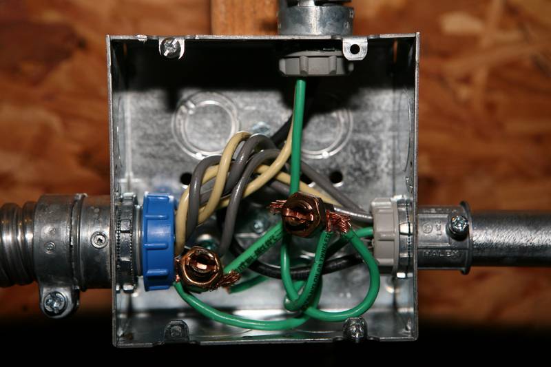
Next: Another municipality required installation change.
Best regards,
Bill -
Re: Illustration of 8 KW (DC) GT Solar PV System Install for Residence in Urban Area
Another municipality required change is required usage of exposed #6 grounding wire to interconnect the panel rails. 8 AWG or smaller is not acceptable for my City.
In the image below (4:30 PM Central), the ground wire (hard to see) goes from rail to rail, and, connects on either side of rail splices.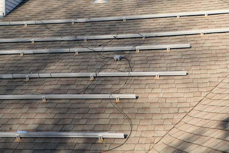
Plastic cable ties won't be usable either, per City requirement: "Cable ties shall not be used to secure exposed wiring between modules. Approved clips, stainless steel cable ties, or stainless steel pipe clamps with rubber inserts are acceptable."
Next: Wiring changes for neutral and ground wires from DC Disconnect Switch to service panel.
Best regards,
Bill -
Re: Illustration of 8 KW (DC) GT Solar PV System Install for Residence in Urban Area
Once again, not to pick nits, but what time of day is this picture taken? What's up with all the shadows? Ouch!
Tony -
Re: Illustration of 8 KW (DC) GT Solar PV System Install for Residence in Urban AreaOnce again, not to pick nits, but what time of day is this picture taken? What's up with all the shadows? Ouch!
Tony
Tony, I'm OK with all comments and questions. I've learned a lot from many here and am very appreciative.
I went back and added time of day for each recent shot.
Last picture shown above was shot at about 4:30 PM CST in Dallas, about 1 hour before sunset.
For today, 12/28, for Dallas:- Sunrise at 7:29 AM in direction 117° East-southeast
- Sunset at 5:29 PM in direction 243° West-southwest
- Duration of day: 10 hours (19 seconds longer than yesterday)
- Sun in south at 12:29 PM at altitude 34° above horizon
Best regards,
Bill -
Re: Illustration of 8 KW (DC) GT Solar PV System Install for Residence in Urban Area
OK, moving to neutral wiring design on the AC side of the inverter that I wasn't aware of until being pointed out by the City's inspector as being needed.
The key point is this wire must travel from the inverter directly to the electric service panel without connection to anything in between.
For example, my neutral wire coming out of the inverter goes to the AC Disconnect switch, then to the Solar kWh meter, then to the electric service panel. At each place, the neutral remains 'floating,' until at the service panel, where here it's connected to the neutral bus.
It doesn't connect to the meter's neutral/ground terminals, for example. My understanding is the neutral is a current carrying conductor. And thus, if it were connected to the meter's neutral/ground, then the conduit, outside, physically connecting the meter to the panel, would carry most of the neutral's current.
Here are pictures to illustrate. The first is the AC Disconnect, the first stop for the neutral after coming out of the inverter. Here you see it simply continues on, without connection to anything.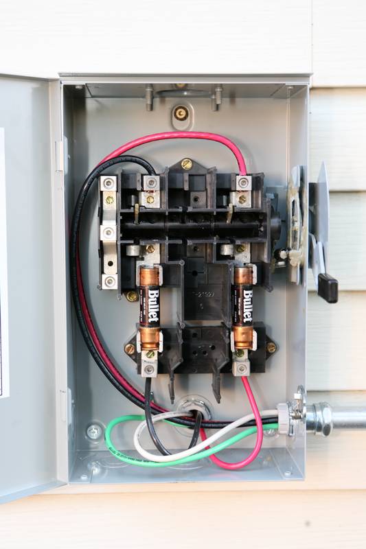
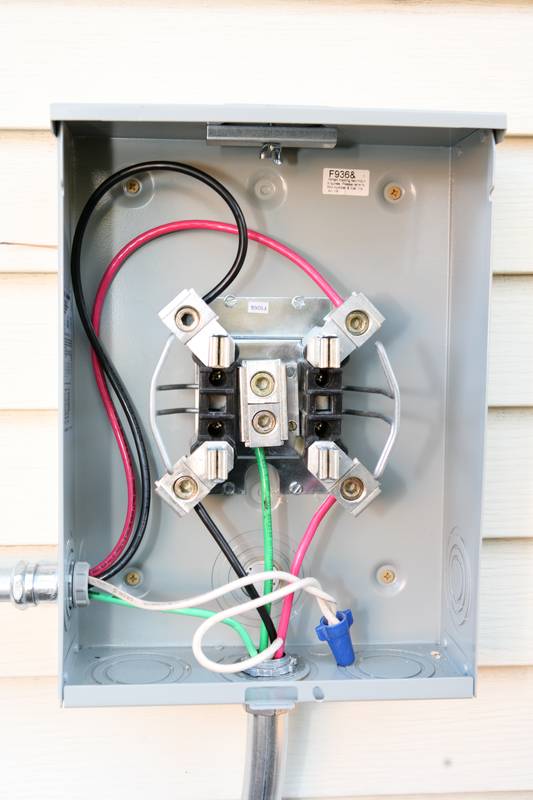
This second image is the solar kWh meter socket, the next stop. Here the neutral wire is *not* connected to the terminal shared with the ground wire. Instead, it simply continues on, via a wire nut connection, to the service panel's neutral bus, where the connection to ground is made.
Next: Wire size is determined by meter socket rating, not inverter output.
Best regards,
Bill -
Re: Illustration of 8 KW (DC) GT Solar PV System Install for Residence in Urban Area
The neutral is not current carrying but is a requirement of UL1741-2005 requirements for checking the balance between the 240 legs. All 240V Gridtie inverters are requirement to check the balance of phase to neutral, but the power electronics don't use the neutral, the load is strictly on the hots
As for not bonding neutral to ground except at the main service panel, that is the very most basic of home wiring NEC rules and nothing to do with PV
Also, the ground requirement again is standard install ( using bare and continuous ground ), nothing special about your location
Any licensed and experienced electrician would have done these properly and further points to the abundance of errors your installer has done. I'm posting this as your update seem to let the installer off the hook, everything wrong with this install, and its become the poster child of how not to do a PV system points to a company that's clueless about NEC and UL requirements for PV installations.
You additional pictures show your shading is so bad, I wouldn't put PV on that roof. You only clear for about 3 hours on the main roof and about 4 hours on the garage.
Someone is going to go bankrupt installing systems with these site conditions ... when this happens is the bank going to come strip the PV off your roof as collateral to the installers business? -
Re: Illustration of 8 KW (DC) GT Solar PV System Install for Residence in Urban Area
SG, much appreciate the comments.
With respect to the shading, I've already been looking at what amount of tree trimming is within my ability, to increase solar insolation.
I've learned further about the neutral and its purpose - PV and non-PV - from your posting. Thanks.
Best regards,
Bill -
Re: Illustration of 8 KW (DC) GT Solar PV System Install for Residence in Urban Area
Keep in mind, your shading will only get worse as the trees grown over time, so what you have today is your best case, and I wouldn't be surprised that in 15 years you get only an hour of clear sun on that roof.
You really need to consider removing the offending trees, its a necessary evil for PV and your not the first person to find this out late in the project.
Keep the trees? then expect your tree trimming to cost more yearly than the enegry the PV system generates ( value wise )
It really simple, lots of shade = PV isn't for you. -
Re: Illustration of 8 KW (DC) GT Solar PV System Install for Residence in Urban AreaSolar Guppy wrote: »
...Keep the trees? then expect your tree trimming to cost more yearly than the enegry the PV system generates ( value wise )
It really simple, lots of shade = PV isn't for you.
SG, much appreciated commentary. I'm learning.
Many thanks.
Best regards,
Bill -
Re: Illustration of 8 KW (DC) GT Solar PV System Install for Residence in Urban Area
Some new learning about wire sizing associated with device labeling:
For a 40 Amp back-fed solar AC circuit to the electric service panel, this would normally be 8 AWG wire from the inverter AC output, through the AC Disconnect Switch, through the solar kWh meter socket, and on to the service panel.
The inspector pointed out the solar kWh meter socket is labeled for a minimum wire size of 6 AWG. Thus #8 wire is not acceptable for incoming or outgoing wires at the solar meter socket.
8 AWG, coming out of the inverter's AC output, to the AC disconnect switch, is fine because the switch is labeled for a minimum wire size of 8 AWG. But from this point, to the meter socket, and on to the service panel, it needs to be 6 AWG due to the meter socket's labeling.
The circuit breaker stays at 40 A.
I further learned the common minimum meter socket current size is 60 A, which dictates the minimum 6 AWG wire label. And I learned it's not common to find smaller than 60 A meter sockets.
The 2 images I posted earlier, for discussion on the neutral wire, are applicable here too.
Next: Ground wire specifics between the inverter and the electric service panel.
Best regards,
Bill -
Re: Illustration of 8 KW (DC) GT Solar PV System Install for Residence in Urban Area
Here's a puzzling subject with respect to the ground wires between the inverter and the electric service panel.
I would have thought the ground wire, starting at the inverter's AC output ground terminal, would first go to the AC Disconnect Switch frame, then to the solar kWh meter socket ground connection, and then finally to the service panel's ground bus.
Instead, the inspector pointed out that 2 ground wires are needed:- The first starts at the inverter's AC output section, then to the AC Disconnect Switch frame, then straight to the service panel's ground bus, bypassing the meter socket ground connection.
- The second starts at the meter socket's ground terminal and also terminates at the service panel's ground bus.
Here are pictures, repeated from earlier in the thread, showing the 2 ground wires. The first comes from the inverter AC ground terminal, picks up the AC Disconnect Switch's box frame (difficult to see), and then passes through the meter socket straight to the service panel (bottom). It's one continuous wire with no wire nut connections. The second starts at the meter socket (bottom) and also terminates at the service panel.
Next: Misc updates.
Best regards,
Bill -
Re: Illustration of 8 KW (DC) GT Solar PV System Install for Residence in Urban Area
Can you use a crowbar to cram any more wire nuts in there ??
I also agree with the watertight comments, water always finds a way in, needs a Skystream weep hole to let it out.Powerfab top of pole PV mount | Listeroid 6/1 w/st5 gen head | XW6048 inverter/chgr | Iota 48V/15A charger | Morningstar 60A MPPT | 48V, 800A NiFe Battery (in series)| 15, Evergreen 205w "12V" PV array on pole | Midnight ePanel | Grundfos 10 SO5-9 with 3 wire Franklin Electric motor (1/2hp 240V 1ph ) on a timer for 3 hr noontime run - Runs off PV ||
|| Midnight Classic 200 | 10, Evergreen 200w in a 160VOC array ||
|| VEC1093 12V Charger | Maha C401 aa/aaa Charger | SureSine | Sunsaver MPPT 15A
solar: http://tinyurl.com/LMR-Solar
gen: http://tinyurl.com/LMR-Lister , -
Re: Illustration of 8 KW (DC) GT Solar PV System Install for Residence in Urban Area... water always finds a way in, needs a Skystream weep hole to let it out.
Mike, thanks. What is a "Skystream weep hole?"
Best regards,
Bill -
Re: Illustration of 8 KW (DC) GT Solar PV System Install for Residence in Urban Area
Here are comments and images to catch up to current status.
All AC wiring is complete. Sunny Boy 6000 inverter is inside the garage. 40 A AC back-feed circuit comes outside to 60 A AC Disconnect switch, then to solar kWh 60 A meter, then goes back inside to a 40 A circuit breaker in the service panel. Here's an image of the finished outside AC circuit work: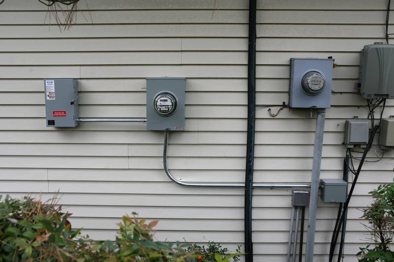
Inside the garage, here's an image showing the 2 ground wires (left side) previously discussed, connecting to the service panel's ground bus, and the inverter's direct-to-the-service-panel neutral (right side) connecting to the panel's neutral bus.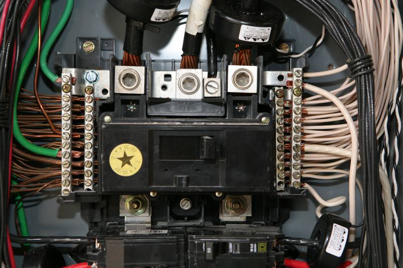
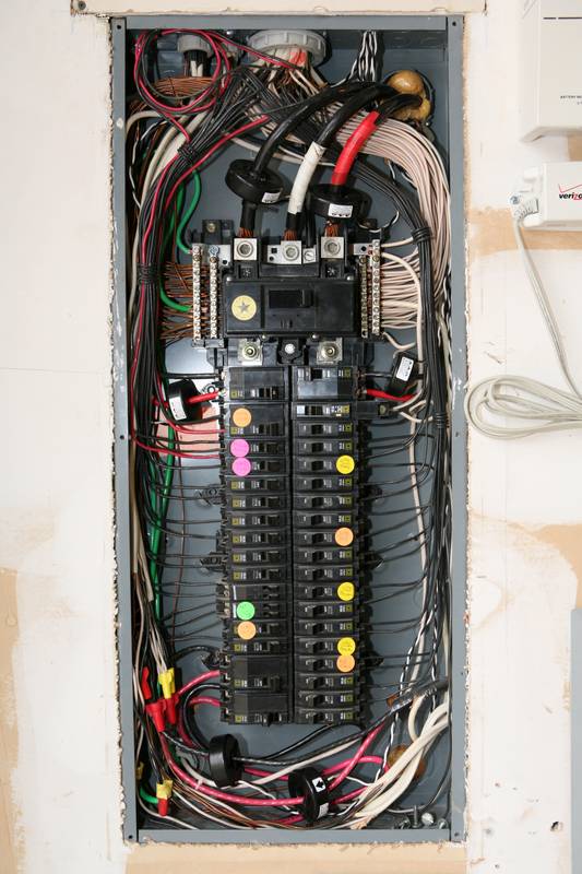
On the 1st page of this thread I showed an image of the inside of the service panel. Work completed in the panel now includes:- A couple of circuits were combined to make room, at the bottom (left) for the inverter back-fed 40 A 2-pole breaker.
- 6 AWG wires, from the solar kWh meter socket, connect to this breaker.
- The low voltage wiring attached to 3 sets of current transformers (part of an existing power monitoring system, not associated with the solar PV project) has been installed inside the panel so the panel's cover can be put on properly.
Shown below is the finished garage interior where the panel (left) and inverter (far right) are.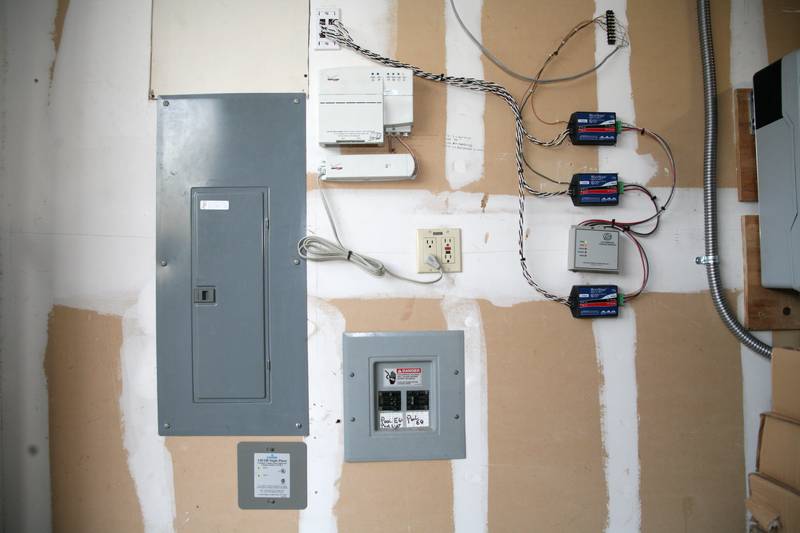
Steps yet to be completed, that I'm aware of, include:- Some remaining wiring work on top of the garage roof.
- Installing PV panels on the roof.
- Wire management on the roof per City/NEC code.
- Labeling circuit/equipment labeling per City/NEC requirements.
- Some number of inspections as required (City, and possibly Oncor (electric utility) and/or the financing firm).
Shown below is rare snow/ice we had in Dallas a few days ago on Christmas day (image shot at 8:40 AM CST). While we get snow/ice maybe once each Winter, we haven't had a 'White Christmas' here since 1898, according to a news report.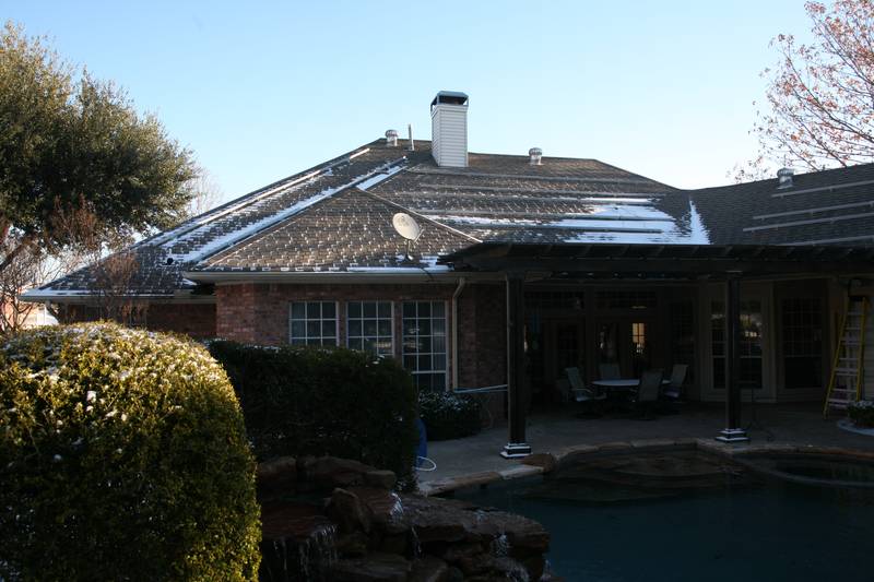
Best regards,
Bill -
Re: Illustration of 8 KW (DC) GT Solar PV System Install for Residence in Urban Area
my hat's off to whoever wired all of that in the main box. i even see ferrites.8) -
Re: Illustration of 8 KW (DC) GT Solar PV System Install for Residence in Urban Area
I still see shadows,, I wait with restless anticipation to see what the production numbers are.
Tony -
Re: Illustration of 8 KW (DC) GT Solar PV System Install for Residence in Urban AreaMike, thanks. What is a "Skystream weep hole?"
Best regards,
Bill
Water was getting inside the Skystream wind gen housings, and would freeze, causing the windmill to stop. The "factory solution" was to drill a hole in the bottom of the nacelle, to let the water out. (at the top of a 30 - 100' tower) $3 for a nice drill bit, and $600 for the tower crew. Homeowners cost.Powerfab top of pole PV mount | Listeroid 6/1 w/st5 gen head | XW6048 inverter/chgr | Iota 48V/15A charger | Morningstar 60A MPPT | 48V, 800A NiFe Battery (in series)| 15, Evergreen 205w "12V" PV array on pole | Midnight ePanel | Grundfos 10 SO5-9 with 3 wire Franklin Electric motor (1/2hp 240V 1ph ) on a timer for 3 hr noontime run - Runs off PV ||
|| Midnight Classic 200 | 10, Evergreen 200w in a 160VOC array ||
|| VEC1093 12V Charger | Maha C401 aa/aaa Charger | SureSine | Sunsaver MPPT 15A
solar: http://tinyurl.com/LMR-Solar
gen: http://tinyurl.com/LMR-Lister , -
Re: Illustration of 8 KW (DC) GT Solar PV System Install for Residence in Urban Area
Those "ferrites" might be current transformers for some sort of AC monitor (like a TED or similar).
-BillNear San Francisco California: 3.5kWatt Grid Tied Solar power system+small backup genset -
Re: Illustration of 8 KW (DC) GT Solar PV System Install for Residence in Urban Area
you are correct bill as upon closer inspection of the pics i see wires coming off of them. very neat job.:D -
Re: Illustration of 8 KW (DC) GT Solar PV System Install for Residence in Urban Areamy hat's off to whoever wired all of that in the main box. i even see ferrites.8)
The electric service panel wiring was done by the residential electrical contractor at the time the house was built, in 1992.
Later, in 1996, the pool contractor did the break-out box add-on (bottom right of panel), as the panel was already full with circuit breakers.
For the solar PV project, 2 circuits had to be combined to make room for the 40 A 2-pole inverter-back-fed breaker at bottom left.
I installed the current transformers in 2007 at the time of installing geothermal heating/cooling. Two of them provide power monitoring data, along with temperature sensing data, for the geothermal system's COP efficiency for heating, and EER for cooling, among other things. Other CTs are installed for total house consumption, pool, and base load.
I'll be adding 2 more current transformers for the inverter's AC output, probably down in the lower left corner of the panel.
I'm not sure what the presentation of solar kWh output will look like yet. Since keen interest is on just how well the solar PV system will produce power in the face of multiple panel orientations, multiple string orientations, a single inverter, and shading, I'll start with simply a presentation of solar produced kWh production, going the negative direction on this already existing real time monkly kWh consumption online chart: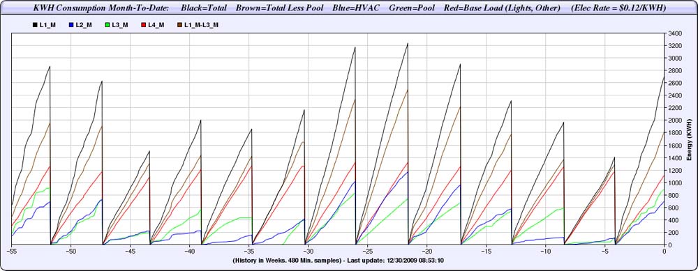
Best regards,
Bill -
Re: Illustration of 8 KW (DC) GT Solar PV System Install for Residence in Urban AreaI still see shadows,, I wait with restless anticipation to see what the production numbers are.
I think PVWatts does a good job of establishing reference output baseline.
If all 36 of my panels are placed at 180° azimuth, are at Lat. tilt (33.156°), and have zero shade, then, using Ver 2 to get to my exact location, annual solar output is estimated to be 11.1 mWh. This is the estimated reference output.
The chart below shows adjustments for actual azimuth and tilt. The default 77% DC to AC Derate Factor is still assumed (zero shade, no impact from multiple panel orientation on one of the strings and multiple panel orientation from string to string). Now estimated annual solar output is 10.2 mWh, which is 92% of estimated reference output.
What's left to influence an estimate are unknown factors, including shading and a common inverter with multiple panel orientation within a string and multiple string orientation. These additional factors will further push down the estimated percentage of reference output.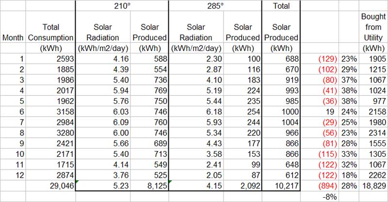
Best regards,
Bill


Categories
- All Categories
- 233 Forum & Website
- 140 Solar Forum News and Announcements
- 1.3K Solar News, Reviews, & Product Announcements
- 181 Solar Information links & sources, event announcements
- 895 Solar Product Reviews & Opinions
- 252 Solar Skeptics, Hype, & Scams Corner
- 22.5K Solar Electric Power, Wind Power & Balance of System
- 3.5K General Solar Power Topics
- 6.7K Solar Beginners Corner
- 1K PV Installers Forum - NEC, Wiring, Installation
- 2.1K Advanced Solar Electric Technical Forum
- 5.6K Off Grid Solar & Battery Systems
- 428 Caravan, Recreational Vehicle, and Marine Power Systems
- 1.1K Grid Tie and Grid Interactive Systems
- 656 Solar Water Pumping
- 816 Wind Power Generation
- 621 Energy Use & Conservation
- 623 Discussion Forums/Café
- 316 In the Weeds--Member's Choice
- 74 Construction
- 125 New Battery Technologies
- 108 Old Battery Tech Discussions
- 3.8K Solar News - Automatic Feed
- 3.8K Solar Energy News RSS Feed