Help with seting over volt disc. and charge limit on MT50
Comments
-
 Hi:
Hi:
With the Epever charge controller (large heat sinks) and the MT50
Can I just set the charge controller to User, Temp 0, Charge Limit 29.2, Float charge to 27.2, and Eq. Time to 0.
I am thinking this should stop my system from overcharging the 8 3.2v 100ah batteries in series (24v system)?
-
The charge controller only "knows" the overall battery bank voltage (12.xxx volts). The BMS's job is to monitor each cell's (or parallel group of cells) voltages (and balance them if the BMS has the "balance" function).
In general, lead acid batteries are much more tolerant of over charging--They just "gas". And they are tolerant of overcharging (to a degree), the EQ charge (equalizing charge) uses that fact to "top balance" the Lead Acid battery by the charge controller charging a 12 volt battery bank by 15-16 volts for a limited amount of time and current (typically an hour or a couple at 2.5% to 5% rate of charge).
Flooded cell lead acid batteries have a propensity to "drift" between cells (self discharge) much more than Li Ion (or even AGM). So monthly EQ is a typical recommendation. Also, EQ can help "mix" the electrolyte and shed the small amount of inactive lead sulfate (sulfation) from the battery plates.
With Li Ion batteries, they do not tolerate excessive charging voltage at all. Many Lithium Ion chemisty batteries can even catch fire if overcharged (or over discharged). So battery management systems were created to ensure that each cell in a Li Ion battery bank is protected (the BMS ensuring that the battery/cell voltage never goes outside the "safe voltage range"). And some BMS can even actively balance a cell (or group of cells) to ensure that all are at the same state of charge.
For Li Ion battery banks used in homes, some version of LiFePO4 battery chemistry is used (lithium iron phosphate). These types of batteries still "don't like" over/under voltage events (which can damage/ruin cells), that at least will not catch fire under normal operation. The downside is that Lithium Iron Phosphate batteries are not as "powerful" as other Li Ion types (somewhat less energy density, less output current per cubic inch). Of course, for a home (or RV), a slightly larger/heavier battery is not a big issue--While safety is (not a drone aircraft which need to be as light as possible).
If you choose not to use a BMS on a LiFePO4 battery bank--Your risk is, as batteries slowly drift State of Charge overtime, the overall 14.8 volts (example 3.7 volts per cell charged) is no longer "true". Instead you could have one cell at 4.0 volts, and the other three cells at 3.6 volts for a bank total of 14.8 volts. With the 4.0 volt cell being "ruined" by over voltage (and other Li Ion chemistries actually "catching fire").
You end up with the question of how long/how many cycles it takes for series cells to "drift"... I don't know, is it 1+ years? Do you check the bank "per cell" voltages once every month during normal inspection--And if you find "drift" (cells varying by 0.050 volts or more from high to low--where you aim for 3.700 volts charged and 3.750 volts never to exceed?) you actively balance the high/low cells (either by charging the low cells or discharging the high cells) and get them to 3.700 volts each?
I have no experience with Li Ion battery banks (other than in things such as laptop computers and flashlights)--So while I understand the basics and reasonings--I cannot give you actual experience (i.e., no BMS, how often to check balance and how often "balancing" is required).
Battery banks are, in some ways, more dangerous that storing a couple gallons of gasoline in a fuel tank (for energy storage). With gasoline, as long as the fuel is in a tank/fuel lines, there is no oxygen, so it cannot burn. Batteries are "self contained" (especially Li Ion batteries). They do not need external oxygen (or water) to "catch fire". They can simply be operated outside their "safe" range and "catch fire". And there is really no practical method to stop the fire once started (water makes the fire worse; powered copper "fire extinguishers" are used for "metal fires"--But hard to get the powder inside a battery bank--So usually lots of water to keep fire from spreading until fuel is expended).
LiFePO4 chemistry batteries are more stable. And designed to no self ignite (you can even drive a nail through a battery and it should not catch fire). So a BMS is not "needed" for safety, but desirable to prevent a single point monitoring system (like a solar charge controller) from overcharging/over discharging a string of 4x series cells (for 12 volt LiFePO4 type) and damaging/ruining one or more (expensive) cells. (BMS can also have other features--Such as over current detection/shutdown as this can also damage the cells, operation outside of allowed battery temperature range, strip heaters for cold weather operation, other cell failures, etc).
A BMS cannot protect against outside events (car crash, genset fuel catching fire and spreading to battery bank, etc.).... So placing a Li Ion battery bank outside the home/living space is still a good idea (even for normal lead acid battery banks, outside the living area/good ventilation/etc. are also recommended). And even a BMS can not protect against a BMS failure (actual failure, or failures a BMS was not designed to protect against):
http://www.batteryvehiclesociety.org.uk/bvsorguk/forums/viewtopic.php?t=1825 (LiFePO4 fire, cause unknown, possibly balancing during freezing conditions)
And as in many fires--The actual failure may never been known as the fire has obliterated much of the physical evidence.
Good practices (correctly sized wiring, properly used fusing/circuit breakers, security to prevent children/falling tools causing issues, etc.) also reduces the chances of electrical fires...
Again, there are folks here that know much more about actual nuts and bolts of safe Li Ion battery usage...
And there is simply a person's risk tolerance (real and perceived). Electricity, propane, liquid fuels, natural gas, driving a car, riding a bicycle, etc. all have various levels of risk. Some risk is cost of failures (replacing appliance, smoke damage from fire) and bodily harm (cyclist run over by a car, slips on icy/wet/gravel roads), etc... One way to look at issues is "risk vs reward". Does the LiFePO4 (or similar "safe" lithium chemistry) battery bank have more advantages (light weight, longer life, less maintenance) than other solutions (lead acid battery, generator, etc.) for you vs the (usual) cost/risk of cell failures vs the "cost/risks" of BMS or no BMS.
BMS have a cost--And they can fail too...
-BillNear San Francisco California: 3.5kWatt Grid Tied Solar power system+small backup genset -
Hi
This is the basic layout of my solar system I want to install this BMS
but I am not sure where the connections should go.
I know where B1 to B8 should connect
Help !
projectile -
One question on the "shunt" function... As you have wired, the "charge controller" current flow to the battery bank will be "invisible" to the shunt.
If you want to see both discharge and charging current (such as a BMS based monitor), then the negative lead (and all loads) should be connected to the "left side" of the shunt (battery negative should be only connection on the "right side" of the shunt).
-BillNear San Francisco California: 3.5kWatt Grid Tied Solar power system+small backup genset -
ok
I understand about moving the charge controller negative to the left of the shunt.
I will do that.
should I connect the inverter negative to the left of the shunt?
I can see that I have to connect the B- on BMS to the left of the shunt.
In the BMS diagram, what is the discharger?
-
Oops, I am sorry I misread you diagram.As you have wired, one connection to battery on left. All other connections on right side of shunt. Including any ground connections (chassis, green wire safety, etc.).I mixed up the inverter vs battery block.Bill
 Near San Francisco California: 3.5kWatt Grid Tied Solar power system+small backup genset
 -
no problem.
can see that I have to connect the B- on BMS to the left of the shunt.
is that correct?
In the BMS diagram, what is the discharger?
-
Left or right side of shunt... Does not matter to the shunt (it does not care). However, what does matter is the BMS or Voltmeter (current meter) that connects to the side of the shunt (Kelvin Contacts). For example you want current flowing into the battery (charging) as adding to stored energy. And discharging from the battery subtracting stored energy.
However, the whole +/- current direction into the battery is just a matter of convention (see BMS or Current Meter instructions). If you connect "backwards", just swap the "sense leads" on the shunt (those two tiny screws on the side of the shunt are for the meter sense leads):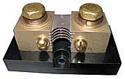
A quick look... The "charger" is your solar battery charger. The "discharger" are you loads....
I am guessing that the BMS treats the two "differently". The discharger (loads) are disconnected if the battery voltage (or cell voltage) falls too low or the discharge current is too high)--You still want the charger connected so that when the loads disconnect/sun rises, the charger can recharge the battery bank.
With the loads, you want them disconnected until the battery gets some charge into them, or until the BMS is reset (like too much current draw--Need to "fix" the loads to prevent excessive current draw)
ADDED:
The Charger is your solar (or other charging sources)--Disconnect the charger if the cells (or overall series stack of cells) reaches the maximum charging voltage (3.75 or 15.0 volts), the charging source gets disconnected... You still want the load connected to bring the per cell voltage down to 3.6 volts (14.4 volts) before the charger is reconnected and starts charging again.
-BillNear San Francisco California: 3.5kWatt Grid Tied Solar power system+small backup genset -
Time for sabbath.
I will look at this Saturday night.
Thanks
All -
I have it now
The charger is the solar charger and the discharger is my inverter.
-
Yes (inverter and/or any "DC" loads).
This BMS protects against "over charging" (the "charger(s)") and over discharging (the inverter+load(s)). And it controls the two types by the needs (turn off charger if over charging, turn off loads if over discharging).
If, for example, you have some other DC loads (lights, cell phone charger, etc.) and were to connect directly to the battery +/- terminals--Those loads could take the battery "dead" and damage the cells (if there is little or no charging current available). And the BMS could not turn off those loads that "bypass" the BMS control.
-BillNear San Francisco California: 3.5kWatt Grid Tied Solar power system+small backup genset -
Hi
i have an 8 cell voltmeter connected to the 8 batteries but it’s reading is alway off.
could it be because I use two different size wire on each lead?
The two different size wires are splice together to form a lead. -
In general, voltmeters draw very little current (a few thousand's of an Ampere)... So wire resistance is of little issue. And for DC voltage/current measurements, spliced wire of different sizes/types don't matter either.
For voltmeters, they can pickup AC ("radio") interference and that can sometimes cause issues... "Twisting" wire (one turn every couple of inches) of the + and - meter leads can help keep interference down. Also, avoid "loops" in the wire run (don't have the + wire take one "run" and the - wire take another "run/path". That can act like a loop antenna. Also, if you have extra wire, instead of placing in a "loop", instead wrap in figure eight "8".
Other things that can cause small voltage errors (when you are trying to measure 3.xxx volts), Dirty/corroded/loose connections, if you have a dirty terminal block, etc. that can create an offset voltage at a corroded connection (corrosion point can be like a small battery), loose/dirty connections can bring in stray voltages.
If you have a 16 pin (or similar) connector... There is contact lubricant to help keep a good connection.
Gold on gold connections are best... Use something like "Deoxit" on contacts points:
https://caig.com/deoxit-gold-g-series/ (for gold connections)
https://caig.com/deoxit-shield-s-series/ (for tin/other connection types)
In equipment with relays--Do not use Silicone based lubricants... They do out gas, and get into contacts. The small arcs at relay contacts actually changes the silicone grease into glass (and insulators).
If the meter is "accurate" at zero current flow... But drifts as you discharge/charge the battery pack--Then you may have poor electrical connections at the cell itself (resistance between cell and voltmeter leads, causes voltage drop: V=I*R).
Other than the above--I don't know what else to do other than calibrate the meter (if you can).
-BillNear San Francisco California: 3.5kWatt Grid Tied Solar power system+small backup genset -
I should also add--Do not run your voltmeter wires in parallel with high current/AC wiring... That can couple noise from that wiring into the sense leads.
Cross AC/heavy DC wiring at "right angles" to avoid coupling noise into the sense leads.
Example of Cat5 or Cat3 "Internet" cable twisted pairs.
-BillNear San Francisco California: 3.5kWatt Grid Tied Solar power system+small backup genset -
When I get the batteries charged to 3.65 I will retest the 8s voltmeter.
Does anyone know where I can get 8s voltmeter cable 9 pin that is about 2ft long?
It has to fit the isDT batteryGO BG-8S
Most of the ones that I see are very short or will take a month to get to me.
-
Comments on this meter:
https://www.amazon.com/CellMeter-Digital-Capacity-Discharger-Backlight/dp/B073W4MDHCThe red JST plugs are the correct size. The white micro plugs will work but you have to be careful since the distance between pins is slightly greater than the micro plugs.The JST with wires are available:
By Amazon Customer on August 28, 2018
https://www.amazon.com/jst-plugs/s?k=jst+plugs
If you have somebody that sells Remote Controlled planes/helicopters/etc., you might get these connectors there.
Be careful, apparently the Red/Black wire locations may not be a common convention, or some vendors may assemble them backwards.
-BillNear San Francisco California: 3.5kWatt Grid Tied Solar power system+small backup genset -
Thanks but they are 5.9 inches still short.
-
I guess you need to be more specific... I have seen 8s cells with 9 and possibly 10 pin connectors... And is this JST-XH 2.5mm or another JST-xx size?
https://www.rcgroups.com/forums/showthread.php?1493712-JST-connector-confusion-the-real-story
Other than making the cables themselves, can find cables on Ebay and other places that are up to 300 mm (~1 foot) long male/female extension cables:
https://www.ebay.com/sch/i.html?_from=R40&_trksid=p2380057.m570.l1313&_nkw=8s+lipo+extension+cable&_sacat=0
https://www.amazon.com/Balance-Extension-RC-Battery-Charging/dp/B08L36NDVX
Finding a local Radio Control or web based hobby shop may help too...
-BillNear San Francisco California: 3.5kWatt Grid Tied Solar power system+small backup genset -
@projectile
Check out the attached PDF, note the 24 volt series configurations on page 2. The second one, named (alt layout) may allow you to use shorter wiring to your meter.
4480W PV, MNE175DR-TR, MN Classic 150, Outback Radian GS4048A, Mate3, 51.2V 360AH nominal LiFePO4, Kohler Pro 5.2E genset.

Categories
- All Categories
- 229 Forum & Website
- 136 Solar Forum News and Announcements
- 1.3K Solar News, Reviews, & Product Announcements
- 179 Solar Information links & sources, event announcements
- 892 Solar Product Reviews & Opinions
- 252 Solar Skeptics, Hype, & Scams Corner
- 22.5K Solar Electric Power, Wind Power & Balance of System
- 3.5K General Solar Power Topics
- 6.7K Solar Beginners Corner
- 1K PV Installers Forum - NEC, Wiring, Installation
- 2.1K Advanced Solar Electric Technical Forum
- 5.6K Off Grid Solar & Battery Systems
- 428 Caravan, Recreational Vehicle, and Marine Power Systems
- 1.1K Grid Tie and Grid Interactive Systems
- 655 Solar Water Pumping
- 816 Wind Power Generation
- 620 Energy Use & Conservation
- 622 Discussion Forums/Café
- 316 In the Weeds--Member's Choice
- 74 Construction
- 125 New Battery Technologies
- 107 Old Battery Tech Discussions
- 3.8K Solar News - Automatic Feed
- 3.8K Solar Energy News RSS Feed