Inverter repair

Comments
-
In general, a large problem with integrated circuits, transistors, and other active/silicon components are dramatically shortened lives from stresses (electrostatic discharge, over voltage, reverse voltage, thermal and mechanical stresses, etc.).Even if you get it running again, it is possible that you may have other failures in the near future because of the reverse power connections.You don't even know which parts where exposed to the voltage issues, without a schematic.I just don't see this as worth the time and money to fix.BillNear San Francisco California: 3.5kWatt Grid Tied Solar power system+small backup genset
-
I agree with Bill.
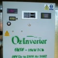
Here below ..... is a copy of my OzInverter build manual from the tech section. Its a straight to the point contribution by a well respected, good and clever engineer in Australia.
"‘Warpspeeds’ comments on limitations of HF (high Frequency) Inverters.
“If you build say a 2Kw high frequency switching power supply to first generate a high dc voltage, and then use PWM to generate a sine wave from that high dc voltage, you are always going to be limited by that 2Kw dc to dc converter.
You cannot suddenly draw 3Kw from it to supply some momentary power surge. There will only ever be 2Kw of dc available.
Now a great steel lump of a transformer driven with PWM straight from a battery is only limited in power by heating of the wire in the transformer, and by the maximum safe current capacity of the mosfets driving that transformer.
Although constant continuous long term power output may still be limited to 2Kw (in this example) you could draw short term power surges of multiples of 2Kw for very short periods without any problem at all.
If you want an inverter that has some real peak surge load grunt, a big lump of iron for the transformer core has all the advantages for a practical inverter.”
‘Warpspeed’ on a Chinese G…..l brand of High Frequency Inverters.
“A High frequency Inverter …………….. It’s the crappy high frequency type that uses five small dc to dc converters in parallel to generate several hundred volts of dc, and then turns that into a modified sine wave. It’s all very highly stressed with light duty parts, and just looking at it the advertised power rating is just a complete total joke.
High frequency inverters are rather fragile and very prone to blowing up. Not necessarily G…..l, but high frequency inverters in general are definitely best avoided.
Much better are the larger transformer inverters, even the modified sinewave types. Better still are the PWM pure sine wave transformer inverters, but all that "goodness" comes at very great extra cost, size, and weight.
A high frequency inverter takes some low voltage dc (12v for G…..l) and generates high voltage dc, usually about 340 volts. It does that with a high frequency switching supply, the G…..l runs about 40Khz, all fairly typical.
Now that is the problem right there. If your switching power supply is designed to deliver 1Kw of power, that is its maximum. It cannot suddenly supply a peak power of 1.1Kw, or 3Kw or 5Kw for a second or two.
Many loads, in fact most loads have high inrush currents when initially switched on, and a high frequency inverter has absolutely zero short term overload capacity, despite what it claims on the front of the inverter.
So you take your 99,000 watt inverter that has a surge capacity of a gazillion watts and plug in one of your power tools pull the trigger, and the smoke escapes from the inverter. Happens all the time...
Now a transformer inverter has a vastly higher overload capacity. It has multiple huge mosfets to ensure low conduction losses, but that also provide massive short term overload capacity. The large transformer and heatsinks can absorb a lot of flash heat, so the inverter will not complain too much about short term overloads.
Now a tiny high frequency switching power supply will have much smaller parts, and just cannot absorb the same type of short term overloads without going bang. Much more stressed, far more fragile. Just a toy really and best avoided for serious usage.”Everything is possible, just give me Time.
The OzInverter man. Normandy France.
3off Hugh P's 3.7m dia wind turbines, (12 years running). ... 5kW PV on 3 Trackers, (8 years) .... 14kW PV AC coupled using Used/second hand GTI's, on my OzInverter created Grid, and back charging with the AC Coupling and OzInverter to my 48v 1300ah batteries.
-
i check the diodes at the input stage and even desolder all the fets and there is still a short circuit existing on the input battery connection.
any ideas guys as to what else could be causing the shorts? -
Any large electrolytic capacitors on the DC input? Look for leaking, swollen, many have an "X" on the back side of the can that expands and bursts if over pressure.
Also, there are different voltages you can use to Ohm check... Typically, modern DMM will use a pretty low voltage to measure Ohms. And there is the "Diode Check" which is >1-2 volts source... With low voltage resistance checks, most diode junctions measure high resistance. At diode check typically somewhere around 0.3 to 0.7 volts or so (forward biased junction in diode/transistor/etc.).
To check for shorts... use a low voltage current source (0.1 to 1.0 volts or so) and get 0.1 amps or so flowing through the circuitry. With a DMM set to 200 mV (0.2 volts) full scale, measure the voltage drop (one meter lead on the source, a second meter lead probing points along the current path(s)). Typically, you will see a "steady voltage" (0.2 volts for example on the + side, or near 0.0 volts on the negative side--Depending on your choices), and you will move around the current paths until your find a big drop (or jump) in voltage... That is typically where the current path went to a dead short to return.
This technique almost always works... Finds shorted components, solder bridges, and even Printed Circuit Board internal shorts. And since you are using low voltage and low currents, you don't usually damage and components.
For diodes, the typically fail open, but diodes (and any silicon devices like transistors, FETs, etc.) can fail open or short.
Good luck,
-BillNear San Francisco California: 3.5kWatt Grid Tied Solar power system+small backup genset -
An interesting read. I nearly bought a 2000 watt Xantrex inverter charger to replace my aging Trace DR1524 MSW. Now I'm thinking perhaps I won't bother. The Trace has a heavy transformer, 4400 watt surge and has proven to be bullet proof. And seems to be just fine running my electric fridge. It was interesting to see that the Xantrex transformer 2800 watt inverter was three times the price of the similar capacity solid state unit they had displayed. I asked he salesman how they could still keep selling a $3000 inverter when they had a perfectly good solid state for less than $1000. I never got a very definitive answer.clockmanfran said:
Much better are the larger transformer inverters, even the modified sinewave types. Better still are the PWM pure sine wave transformer inverters, but all that "goodness" comes at very great extra cost, size, and weight.
A high frequency inverter takes some low voltage dc (12v for G…..l) and generates high voltage dc, usually about 340 volts. It does that with a high frequency switching supply, the G…..l runs about 40Khz, all fairly typical.
Now that is the problem right there. If your switching power supply is designed to deliver 1Kw of power, that is its maximum. It cannot suddenly supply a peak power of 1.1Kw, or 3Kw or 5Kw for a second or two.
Now a transformer inverter has a vastly higher overload capacity. It has multiple huge mosfets to ensure low conduction losses, but that also provide massive short term overload capacity. The large transformer and heatsinks can absorb a lot of flash heat, so the inverter will not complain too much about short term overloads.Island cottage solar system with approximately 2300 watts of panels, 1kw facing southeast 1.3kw facing southwest. All panels in parallel for a 24 volt system. Trace DR1524 MSW inverter which has performed flawlessly since 1994. Outback Flexmax 80 MPPT charge controller four 467A-h AGM batteries. Insignia 11.5 cubic foot electric fridge 1/4hp GSW piston pump. My 32nd year. -
While I feely admit to having limited knowledge about the limits of High frequency inverters. I'm at the point of callinng my 20+ year old l800 watt Prosine pretty much boom proof. It has been pretty much abussed since I decided to forgo buying properly sized unit for my new home, regularly exceeding it's max output and popping it off maybe 50 times the first year and just resetting and continuing, tht was 7 years ago. It lives outside and works from -l0 - l00 degrees. I'm fine with this high frequency inverter. It's now wired in as backup, just replaced this year.706jim said:
An interesting read. I nearly bought a 2000 watt Xantrex inverter charger to replace my aging Trace DR1524 MSW. Now I'm thinking perhaps I won't bother. The Trace has a heavy transformer, 4400 watt surge and has proven to be bullet proof.clockmanfran said:Much better are the larger transformer inverters, even the modified sinewave types. Better still are the PWM pure sine wave transformer inverters, but all that "goodness" comes at very great extra cost, size, and weight.
Home system 4000 watt (Evergreen) array standing, with 2 Midnite Classic Lites, Midnite E-panel, Magnum MS4024, Prosine 1800(now backup) and Exeltech 1100(former backup...lol), 660 ah 24v Forklift battery(now 10 years old). Off grid for 20 years (if I include 8 months on a bicycle).
- Assorted other systems, pieces and to many panels in the closet to not do more projects.

Categories
- All Categories
- 229 Forum & Website
- 136 Solar Forum News and Announcements
- 1.3K Solar News, Reviews, & Product Announcements
- 179 Solar Information links & sources, event announcements
- 892 Solar Product Reviews & Opinions
- 252 Solar Skeptics, Hype, & Scams Corner
- 22.5K Solar Electric Power, Wind Power & Balance of System
- 3.5K General Solar Power Topics
- 6.7K Solar Beginners Corner
- 1K PV Installers Forum - NEC, Wiring, Installation
- 2.1K Advanced Solar Electric Technical Forum
- 5.6K Off Grid Solar & Battery Systems
- 428 Caravan, Recreational Vehicle, and Marine Power Systems
- 1.1K Grid Tie and Grid Interactive Systems
- 655 Solar Water Pumping
- 816 Wind Power Generation
- 620 Energy Use & Conservation
- 622 Discussion Forums/Café
- 316 In the Weeds--Member's Choice
- 74 Construction
- 125 New Battery Technologies
- 107 Old Battery Tech Discussions
- 3.8K Solar News - Automatic Feed
- 3.8K Solar Energy News RSS Feed