Solar Dilemma
Comments
-
Re: Solar Dilemma
Hi,
Back with a little more information in the bucket.
Here is a diagram of the situation. I've "mostly" figured it out but for one detail.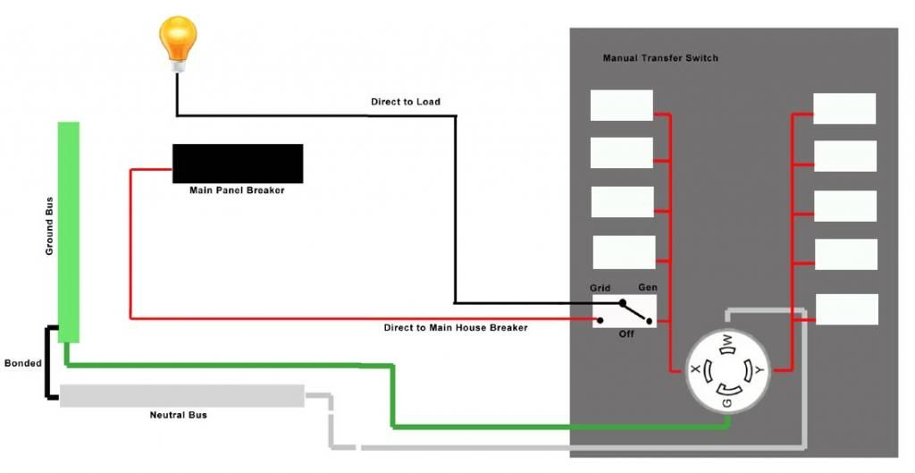
Pictured is the Manual Transfer Switch, with it's L14-30R 4 prong connector and ONE circuit switch marked Grid, Gen and Off.
As you can see, by flipping the switch, the source of power is selected between the Grid and the Generator.
(Except in this case, I want to use the ProWatt INVERTER instead of the Generator.)
Everything is straight forward EXCEPT, as you can see, the Neural and Ground are Bonded in the House panel But NOT in the Inverter.
As you might recall, I'm trying to connect the R15, 3 prong (common 15A home Outlet configuration) Inverter output To the L14-30R 4 prong receptacle on the Manual Transfer Switch.
So, as is, if I connect the Inverter, the Neutral and Ground are shorted to each other in the inverter.
But the inverter has a Floating Neutral.
So, If I were to disconnect the Ground wire in the Adapter cord I made on the L14-30R plug and only connect the hot and Neutral, then it would probably work since the bonded neutral ground dilemma would be resolved. (Or not?)
Problem is, that might not be exactly safe.
I do also realize that only 5 of the 10 circuits on the Manual transfer switch would work this way because there are two banks of Switches.
The Engineer at Connecticut Electric said I could simply JUMP the Hots together and utilize all 10 that way since when on the Inverter
the power is totally isolated from the House panel and it's not going 240v. ONLY 120v.
Do you see any flaws in this? Is there a way to resolve this neutral ground bond dilemma safely?
Thanks again. -
Re: Solar DilemmaKnowledgeSponge wrote: »Hi,
Back with a little more information in the bucket.
Here is a diagram of the situation. I've "mostly" figured it out but for one detail.
The drawing looks correct. You merely want to sub the inverter for the generator (on one hot side).Everything is straight forward EXCEPT, as you can see, the Neural and Ground are Bonded in the House panel But NOT in the Inverter.
This is in fact how you want it. Trouble arises if there is an N-G bond in both locations as it creates a ground loop (current can flow through both neutral and ground wires as they are paralleled at both ends). This is particularly problematic if the power source has GFCI as current flowing along the ground wire takes away from the current flowing on the neutral which is what the ground-fault circuitry compares to hot to detect an imbalance.So, If I were to disconnect the Ground wire in the Adapter cord I made on the L14-30R plug and only connect the hot and Neutral, then it would probably work since the bonded neutral ground dilemma would be resolved. (Or not?)
Problem is, that might not be exactly safe.
Leaving the ground connection between inverter and power panel out would eliminated the ground loop potential and not allow the current division described above. Is it safe? Not really, as it means the inverter is ungrounded. If you then connect the inverter to ground separately, the parallel current path can be made within the Earth itself and you're right back where you started. Again, this only occurs if there is an N-G bond in both locations.I do also realize that only 5 of the 10 circuits on the Manual transfer switch would work this way because there are two banks of Switches.
The Engineer at Connecticut Electric said I could simply JUMP the Hots together and utilize all 10 that way since when on the Inverter
the power is totally isolated from the House panel and it's not going 240v. ONLY 120v.
Although others will warn about the dangers of overloading an inverter if this is done, the truth is a good inverter will fault without damage before this happens. It is a very small inverter, and probably could be easily overloaded if asked to power things on both hot lines.
This should work. -
Re: Solar Dilemma
Thanks Cariboocoot !!! -
Re: Solar DilemmaCariboocoot wrote: »The drawing looks correct. You merely want to sub the inverter for the generator (on one hot side).
This is in fact how you want it. Trouble arises if there is an N-G bond in both locations as it creates a ground loop (current can flow through both neutral and ground wires as they are paralleled at both ends). This is particularly problematic if the power source has GFCI as current flowing along the ground wire takes away from the current flowing on the neutral which is what the ground-fault circuitry compares to hot to detect an imbalance.
The Inverter does in fact have a GFCI outlet. So you're saying that I WANT the Inverter to be Floating Neutral and the House panel to have Ground-Neutral bond?
(Which is in fact the way it is right now) Are you saying I should remove the GFCI outlet and install a non GFCI outlet in the Inverter?Cariboocoot wrote: »Leaving the ground connection between inverter and power panel out would eliminated the ground loop potential and not allow the current division described above. Is it safe? Not really, as it means the inverter is ungrounded. If you then connect the inverter to ground separately, the parallel current path can be made within the Earth itself and you're right back where you started. Again, this only occurs if there is an N-G bond in both locations.
There is not a N-G bond in both locations. The Inverter does not have a G-N bond. The house panel does. Yet, this set up still does not work and
I'm still baffled. When I attempt to connect the inverter, it hums heavily and doesn't come on. If it was simply the Inverter detecting a ground fault, wouldn't
the GFCI simply pop? (It doesn't)Cariboocoot wrote: »Although others will warn about the dangers of overloading an inverter if this is done, the truth is a good inverter will fault without damage before this happens. It is a very small inverter, and probably could be easily overloaded if asked to power things on both hot lines.
This should work.
I agree, it should. And that was the opinion of the engineers at Xantrex AND Connecticut Electric (Transfer Switch Manufacturer)
And yet, I still have a problem. MORE study
-
Re: Solar DilemmaKnowledgeSponge wrote: »When I attempt to connect the inverter, it hums heavily and doesn't come on.
Turn on the inverter, plug something in it, such as a lamp. Make sure the lamp lights up. Then connet it through the other half of the outlet. Try the loads. Do they get powered? Does GFCI trip? Is the lamp still on? -
Re: Solar Dilemma
I'd remove the GFCI outlet. The things are problematic no matter what, and are best when installed at the point of power use not at the point of power generation. Sometimes they false trip even when properly installed and no problem can be detected.
With the ground wire left out the inverter should still be able to power a load with hot and neutral only, just as Northguy said. Isolate one line for this and just use a simple (preferably incandescent) lamp; no sense trying to power up anything more until you know you got the wires right. -
Re: Solar DilemmaTurn on the inverter, plug something in it, such as a lamp. Make sure the lamp lights up. Then connet it through the other half of the outlet. Try the loads. Do they get powered? Does GFCI trip? Is the lamp still on?
NorthGuy, not exactly sure what you mean by this, sry.
If I plug a lamp directly into the Inverter, it works fine.
But what do you mean by "Connect it through the other half of the outlet"?
The Inverter has one GFCI outlet, and on that outlet are two receptacles.
Do you mean plug the lamp into both receptacles to be sure they both work?
Thanks -
Re: Solar DilemmaKnowledgeSponge wrote: »But what do you mean by "Connect it through the other half of the outlet"?
The Inverter has one GFCI outlet, and on that outlet are two receptacles.
Do you mean plug the lamp into both receptacles to be sure they both work?
Put the lamp into one receptacle. Then use the other receptacle to connect to the transfer switch. -
Re: Solar DilemmaPut the lamp into one receptacle. Then use the other receptacle to connect to the transfer switch.
Ahhh ok.
All the while, I'm trying to be VERY cautious about connecting the ProWatt Inverter again because they're around $400
so it might be just me, but I was trying to perfect the "theory" BEFORE doing any more connecting of the Inverter
I HAD a bud who was an electrical engineer and did code inspections for the City, but unfortunately he passed away recently.
This would have been resolved months ago.
Thanks for everyone's continued help.
I'm SURE this will all be helpful to others who later blaze this same trail. -
Re: Solar Dilemma
Ok, on the latest attempt, the GFCI pops every time I attempt to use Inverter power to the House circuit.
Just tried something interesting.
I checked for Continuity between Hot and Neutral at the Transfer switch which is isolated from the Main Panel and got a positive (yes, continuity) reading
As you can see from the diagram, Neutral at the Transfer Switch is direct connected to the Neutral Bus at the main panel. But in GRID position, I get a continuity reading between Neutral and Hot even though in that position, the Transfer Switch should be completely isolated from the Main Panel.
Odd, Isn't it? -
Re: Solar DilemmaKnowledgeSponge wrote: »Ok, on the latest attempt, the GFCI pops every time I attempt to use Inverter power to the House circuit.
Assuming you wired everything correctly, you have three choices:
- Use different transfer switch (the one that switches neutral)
- Use different inverter - without GFCI
- Remove GFCI from your inverter (Bill has posted instructions in one of the earlier posts.KnowledgeSponge wrote: »I checked for Continuity between Hot and Neutral at the Transfer switch which is isolated from the Main Panel and got a positive (yes, continuity) reading
Assuming you checked this correctly, this is either a load connected somewhere or there's some electronics inside the switch. -
Re: Solar Dilemma
Thanks NG
Will do -
Re: Solar Dilemma
I checked Continuity again today on the ProWatt SW 2000 and there IS continuity between Ground and Neutral.
Wouldn't THAT explain why I'm having these problems?
The Main (House) panel is NG bonded and apparently so is the Prowatt SW 2000. -
Re: Solar Dilemma
You have to use low OHMs scale and it should be pretty much well below 1.0 Ohms measured to be "shorted".
Having a neutral bond in the inverter (before the GFI outlet) and a neutral bond after the GFI (in the house)--That will (virtually always?) pop the GFI.
Correct fix (assuming nothing else is wrong):
1) Remove Neutral+Chassis bond inside inverter
2) Remove GFI on inverter or wire around the GFI (note that GFI outlets usually have two connections on the back--And the second one is GFI protected, so just connecting on the rear of the GFI may not bypass the GFI.
You could just lift the neutral to ground bond on the inverter and use the GFI outlets. Or you could leave the Neutral+ground bond in the inverter and wire around/remove the GFI--It will work, but there is a possibility in some fault conditions that you will toast the neutral wiring from the home to the AC inverter (and through its neutral-chassis-safety ground bond wires). I would try my darnedest to remove the Earth+Neutral bond inside the inverter (should be obvious when you pull the GFI outlet(s)).
Is there some reason you cannot remove the inverter's GFI and Neutral-chassis bond wire?
-BillNear San Francisco California: 3.5kWatt Grid Tied Solar power system+small backup genset -
Re: Solar Dilemma
It would be normal for the Prosine to have an N-G bond before the GFCI circuit. If one is then present after the circuit (as in the power distribution panel) then there are two paths current can 'return' on, one of which (the ground) bypasses the GFCI circuit causing it to read a current imbalance in comparison to the hot side. This will trip the circuit protection; it is what it is supposed to do.
The people who told you there is not N-G bond on the Prosine may be referring to post-GFCI, which is irrelevant as you wouldn't want one there anyway.
As before, remove the GFCI and make sure there is only one N-G bond anywhere. It's amazing how easily these little wiring differences can keep things from working. -
Re: Solar Dilemma
GFCI won't work if there's no Netural to Ground bond behind it, so it has to be there. -
Re: Solar DilemmaGFCI won't work if there's no Neutral to Ground bond behind it, so it has to be there.
Actually, I do not think that is true. The self test may not work, but the actual detection circuit does not "care" if there is a neutral bond or not.
What the GFI does is basically put a current transformer around the Hot and Neutral wire pair. If the current out exactly equals the current returned... All is well.
If the current out is greater or less than ~5 milliAmps vs the neutral lead, then the GFI will open both Hot and Neutral circuits.
Interestingly, if you do not have a Neutral to Safety ground bond, it is possible to "touch" the hot lead and not trip the GFI--This is because there is no current flowing trough your body (or "short to ground") as there is no Neutral to safety ground bond.
You cannot get a shock from a (relatively low voltage/frequency) floating power supply (transformer isolation, or a battery pack) by touching only one lead (or one lead and safety ground).
You only get the "shock" because there is a return path from safety ground back to the neutral wire (neutral to safety ground bond).
-BillNear San Francisco California: 3.5kWatt Grid Tied Solar power system+small backup genset -
Re: Solar DilemmaIs there some reason you cannot remove the inverter's GFI and Neutral-chassis bond wire?
-Bill
Warranty. Snyder electric (bought Xantrex).
It has a 2 year warranty and I bought it two months ago.
If I open or alter it, warranty is void.
But in a way, I don't really "trust" warranties anyway.
So, I may open it any way and the helK with em. -
Re: Solar Dilemma
I Figured out another way to "Test" things.
I have a small, 400 watt Inverter so......
I connected that inverter to the battery and plugged my handy dandy custom made adapter cord (see OP) into the small 400 watt
inverter and then into the Transfer Switch and VIOLIN!, it worked.
So, everything (under 400 watts) worked fine with the small 400 watt Inverter and NOTHING at all works with the Xantrex ProWatt.
On the ProWatt, the GFCI pops EVERY time.
So, I have a choice, do as BB suggested (and void my warranty) or, Don't use the Inverter the way I want to. (through the Manual Transfer Switch)
I could very well run cords through windows etc, but this is a very messy and inconvenient solution for everyday use. -
Re: Solar DilemmaCariboocoot wrote: »It would be normal for the Prosine to have an N-G bond before the GFCI circuit. If one is then present after the circuit (as in the power distribution panel) then there are two paths current can 'return' on, one of which (the ground) bypasses the GFCI circuit causing it to read a current imbalance in comparison to the hot side. This will trip the circuit protection; it is what it is supposed to do.
The people who told you there is not N-G bond on the Prosine may be referring to post-GFCI, which is irrelevant as you wouldn't want one there anyway.
As before, remove the GFCI and make sure there is only one N-G bond anywhere. It's amazing how easily these little wiring differences can keep things from working.
This confuses me just a bit.
Are you saying that the ProWatt Inverter could be wired so that.....( with respect to the Inverter alone, as in free standing and not connected to anything external) the following could be true....
1). There is NO Ground Neutral bond BEFORE the GFCI outlet
2). The GFCI outlet itself is wired such that it (itself) creates a ground neutral bond? ( checked at the receptacle ON the GFCI outlet ) -
Re: Solar Dilemma
Here are a couple links that explain GFI outlets. The basic circuit inside the GFI:
http://www.diychatroom.com/f18/can-gfi-work-no-ground-wire-43549/
Wiring downstream outlets from a "master" GFI outlet:
http://www.thecircuitdetective.com/gfis.htm
-BillNear San Francisco California: 3.5kWatt Grid Tied Solar power system+small backup genset -
-
Re: Solar DilemmaKnowledgeSponge wrote: »This confuses me just a bit.
Are you saying that the ProWatt Inverter could be wired so that.....( with respect to the Inverter alone, as in free standing and not connected to anything external) the following could be true....
1). There is NO Ground Neutral bond BEFORE the GFCI outlet
Grounding the Neutral is done in North America to allow the use of single sided fuses in our home/power distribution systems. Neutral is always "at zero volts", so there is no need for a breaker/fuse on the Neutral wire. Grounding the neutral also prevents static charges and can help reduce lightning surges too.
Floating power supplies are, in some ways, actually safer. A single short circuit will not draw any power or shock a person. However, if there are two or more shorts, then you can get a shock/short circuit with current flow. Isolation transformers were (are) used in factories when building some electrical appliances for worker safety before High Pot testing is performed--At least this was true in the decades before GFI was ever thought of... Today, a GFI protected outlet would probably be used instead.2). The GFCI outlet itself is wired such that it (itself) creates a ground neutral bond? ( checked at the receptacle ON the GFCI outlet )
The GFI outlet does not create the Neutral to safety ground bond. That is (usually) done back in the Main Breaker panel of the home.
However, GFI outlets can be wired to put a GFI outlet at the sink, and then additional plain outlets can be added to the Output Terminals of the "master GFI outlet" to have GFI protected outlets that share the same circuit.
They may have a self test circuit that draws 10 milliamps or so from the hot to safety ground to test the wiring. But, you could do the same test by connecting the test resistor from GFI "hot" output to Neutral GFI input (to unbalance the current flow "through" the current sense).
-BillNear San Francisco California: 3.5kWatt Grid Tied Solar power system+small backup genset -
Re: Solar DilemmaWhat the GFI does is basically put a current transformer around the Hot and Neutral wire pair. If the current out exactly equals the current returned... All is well.
Exactly. And all will be well forever unless there's an alternative path that takes some current. This alternative path will never exist unless Neutral is bound to the Ground. This alternative path is usually "Hot" - "You" - "Ground" - "Neutral before GFCI". If "Neutral before GFCI" is not connected to "Ground", there's no alternative path and current in is always the same as current out. In such situation GFCI never trips. -
KnowledgeSponge said:I need some help figuring this out.
I have
5 x 100Watt, 12V panels.
1 x Xantrex Prowatt 2000 Inverter
1 x 30A charge controller (not MPPT)
2 x 120Ah batteries
1 x Manual Transfer Switch (for my generator) that's wired to most of the circuits in my home EXCEPT for the Central AC, Water heater, Dryer and Range
But my dilemma is getting the power from the batteries to the desired places in my home.
At first, I thought I was going to make a cable that plugged into the Inverter on one end and the Manual Transfer switch on the other.
This cable would have a standard 15A male outlet plug on one end (to plug into the Inverter) and a 30A, 4 prong twist lock L14-30A female plug for the Transfer switch panel on the other end.
But then I learned about something called a Floating Ground (I think. Even though I couldn't find that mentioned in the Xantrex User Guide)
Anyway, I learned that for reasons I have not yet studied enough to understand you can't do that.
Seems the Inverter will smoke if I connect it to the Manual transfer switch even though the circuit in question is totally isolated from
the grid by way of the manual transfer switch selector switches.
So, now it appears I will have to run extension cables through my house to various appliances or lights I want to power when I want
to use solar power. This goes against almost everything I was trying to do. I wanted to use my Inverter and batteries to power
CIRCUITS in my home so that I could easily plug in to the Manual Transfer Panel and tap the energy stored in the batteries the same
as I connect the generator.
I DO NOT want cords running through windows etc.
Am I going to have to purchase yet another Transfer switch? One that does not utilize floating grounds (or whatever).
One specifically made to work with an Inverter?
Surely there has to be a work around for this?
There IS another thread that deals with this topic and I read it in it's entirety.
But I have a slightly different angle and different gear.
Thanks
In order to hook up a 220 volt inverter to your power pole or mains box, you should have a SPLIT PHASE inverter. Someone below made some sort of suggestion that you could just hook up across both sides with any old inverter, and that will not work. The two sides need to be 180 out of phase for this to work. Otherwise, choose one side, and use it, rewiring circuits you need to that side.
-
How about a real world question:
Is this legal to DIY or operate without inspection at your place? Will your home insurance cover anything if it goes wrong? Will your life-insurance or other insurance still be in effect if you kill yourself, lineman, or others?
The reason I ask is that even IF you DIY everything to code, if it isn't officially inspected / documented, then you are taking a big risk as they will immediately point to the illegal installation.
-
I am not sure about down south, but up here you can do the work and have it inspected, just expect that, unless you are experienced, the inspector may be very picky...
KID #51B 4s 140W to 24V 900Ah C&D AGM
CL#29032 FW 2126/ 2073/ 2133 175A E-Panel WBjr, 3 x 4s 140W to 24V 900Ah C&D AGM
Cotek ST1500W 24V Inverter,OmniCharge 3024,
2 x Cisco WRT54GL i/c DD-WRT Rtr & Bridge,
Eu3/2/1000i Gens, 1680W & E-Panel/WBjr to come, CL #647 asleep
West Chilcotin, BC, Canada -
3 year old thread guys....
1.8kWp CSUN, 10kWh AGM, Midnite Classic 150, Outback VFX3024E,
http://zoneblue.org/cms/page.php?view=off-grid-solar


Categories
- All Categories
- 232 Forum & Website
- 139 Solar Forum News and Announcements
- 1.3K Solar News, Reviews, & Product Announcements
- 181 Solar Information links & sources, event announcements
- 893 Solar Product Reviews & Opinions
- 252 Solar Skeptics, Hype, & Scams Corner
- 22.5K Solar Electric Power, Wind Power & Balance of System
- 3.5K General Solar Power Topics
- 6.7K Solar Beginners Corner
- 1K PV Installers Forum - NEC, Wiring, Installation
- 2.1K Advanced Solar Electric Technical Forum
- 5.6K Off Grid Solar & Battery Systems
- 428 Caravan, Recreational Vehicle, and Marine Power Systems
- 1.1K Grid Tie and Grid Interactive Systems
- 656 Solar Water Pumping
- 816 Wind Power Generation
- 620 Energy Use & Conservation
- 623 Discussion Forums/Café
- 316 In the Weeds--Member's Choice
- 74 Construction
- 125 New Battery Technologies
- 108 Old Battery Tech Discussions
- 3.8K Solar News - Automatic Feed
- 3.8K Solar Energy News RSS Feed