Frustrated-a fairly long post :-(

97TJ
Solar Expert Posts: 68 ✭✭
Well on Saturday morning I drove 4 hours north to my little cabin to install some off grid solar. The cabin is fairly small (20x28 ). It has already been wired by a licensed electrician. The panel consists of two 30 amp, one 20 amp and one 15 amp breaker. One of the 30 amp breakers is wired to a RV cord that plugs into a generator. The 20 amp circuit is for outlets and the 15 amp circuit is for lights. I have been running off the generator for about a year. The other 30 amp breaker is to be used for my solar system. There is a little mechanical device between the two 30 amp breakers to prevent them from both being on at the same time.
All went pretty well installing the solar components (panels, combiner, charge controller, battery bank etc…) except when I attempted to connect the inverter to the 30 amp breaker. Perhaps my choice of inverter was my downfall. I am in the process of contacting the manufacture for suggestions. The inverter I purchased is a Cotek 1000 SK. The US model has a GFI outlet and my thought was to simply run 25’ of 12/2 from the panel to the inverter and plug it in. The problem is that when I plug in the inverter, the GFI shuts down the inverter. Now I did some testing to try and figure out what may be wrong but to no avail and I am now back home and won’t get up there for another month. I hope to have some more Ideas before going back up.
Testing wise here is what I did. First, every indication concerning the solar install seems ok. The controller shows it’s charging to the point of indicating a float charge. After the first time the GFI kicked off the inverter I plugged and extension cord directly to the inverter and plugged in a fan. Worked like a charm. I then with a power strip plugged in the fan, TV, cell phone and radio. Again worked great. So the inverter is working. I then thought that maybe because the 20 amp circuit has a GFI in it that I would turn off that breaker and try again with the 15 amp which is for the lights only. Same result. I then thought I should check the voltage coming from the inverter through the 12/2 I had just pulled and it was approx. 120 volts. I took the end off an extension cord and hard wired that to the panel and plugged into the inverter in an attempt to make sure there wasn’t a problem with the 12/2 I just pulled. Same result. I then decided to plug an extension cord from the inverter to the cord used for the generator and feed it that way. Same result. I then shut off every breaker at the panel and plugged in the inverter and again the GFI kicked off the inverter. When I plug the inverter in, the lights come on for an instant. The inverter doesn’t indicated any overload or anything, the lights all stay green.
Knowing how everything is supposed to be grounded is not always clear to me but I have asked questions and searched the forum and believe that everything should be grounded to a common ground. I therefore grounded everything and I mean every thing to a single point (negative buss bar) and then took that ground to the ground rod connected to the house wiring.
Any suggestions are welcome. Also, one thing I didn’t do was disconnect the solar grounding from that common ground rod and test it.
Comments
-
Re: Frustrated-a fairly long post :-(
Reason #63 why I don't like GFCI.
Sounds like you did all the right things for testing. The fact the inverter will power things directly clearly indicates the problem is inside the breaker box.
My first inclination would be the generator circuit interfering. As the neutral and ground lines aren't switched off with breakers, it's just possible that enough current is flowing back through the gen line to ground causing an imbalance in the GFI which trips it. Was the generator still plugged in? Is there a neutral-ground bond in the breaker box? If so that too can cause an alternate path for the current which creates the imbalance that trips the GFI.
Check these things out and, if necessary, remove the gen connection, in-box neutral-ground bond, or the GFI. -
Re: Frustrated-a fairly long post :-(
ALOT of inverters with a PLUG on the front wrap the ground to neutral..
If you carefully read the manual Samlex, Xantrex, and alot others do this as well..
Could be the issue.. Should be on PAGE #20 in the manual.. Section 3-6 AC Safety Grounding.. -
Re: Frustrated-a fairly long post :-(Knowing how everything is supposed to be grounded is not always clear to me but I have asked questions and searched the forum and believe that everything should be grounded to a common ground. I therefore grounded everything and I mean every thing to a single point (negative buss bar) and then took that ground to the ground rod connected to the house wiring.
Also, one thing I didn’t do was disconnect the solar grounding from that common ground rod and test it.
No expert here but did you try disconnecting the ground from the inverter only?
There is a thread that discussed inverter grounding here recently but I can remember the title right now.
hth
KID #51B 4s 140W to 24V 900Ah C&D AGM
CL#29032 FW 2126/ 2073/ 2133 175A E-Panel WBjr, 3 x 4s 140W to 24V 900Ah C&D AGM
Cotek ST1500W 24V Inverter,OmniCharge 3024,
2 x Cisco WRT54GL i/c DD-WRT Rtr & Bridge,
Eu3/2/1000i Gens, 1680W & E-Panel/WBjr to come, CL #647 asleep
West Chilcotin, BC, Canada -
Re: Frustrated-a fairly long post :-(
Is the ground and neutral bonded in the panel? That would cause the GFI to trip. Ditto if they are bonded in the gen. One additional test would be to connect a GFI between the gen and panel (could just use temp wiring) w/o inverter installed. If it trips with the gen that confirms bonding somewhere in the system. It could also be something in the cabin.
When transferring power with a GFI circuit both the neutral and hot need to be switched. This is typically what a ATS does, it switches both the hot and neutral from one power source another. Your description sounds like panel only switching the hot which would lead to your problem.
All grounds should be bonded as you have done but the hot and neutral on the output of a GFI must be isolated and no bonding on the ground and neutral output. -
Re: Frustrated-a fairly long post :-(
An automatic solution would be to remove any panel or other circuit neutral/ground bonding, add an ATS as the only panel source with gen and inverter inputs to the ATS.
Using an inverter w/o a GFI is not a solution as that would result in double bonding (inverter, panel, gen). -
Re: Frustrated-a fairly long post :-(
Personally, assuming that this is a TSW inverter, which per manual, can have its "white wire" connected to common safety ground--I would remove/wire around the GFI outlet in the inverter. If everything is "perfect" and otherwise wired per code--The standard practice of having the Wire (Neutral) bus bar in the main panel is also connecte to the green wire and metal box common ground too. That is enough "capacitive leakage current" to cause the AC GFI on the inverter to sense the 0.005 Amp (5 mAmp) leakage current and trip. There are "sub panels" with isolated neutral bus bars and that could be an option--but I still would wire around the inverter GFI outlet.
If you still want/need an AC GFI--Put GFI AC outlets in the cabin boxes (typically near sink/tub/shower, out door outlets, etc.). This will protect people and not cause the entire cabin to have an AC power failure if there is a true GFI fault.
-BillNear San Francisco California: 3.5kWatt Grid Tied Solar power system+small backup genset -
Re: Frustrated-a fairly long post :-(
I had this exact same problem with my inverter. I ended up removing the GFCI outlet from the inverter and wiring in a standard outlet. It has worked fine for over a year now. It was an issue having 2 GFCI circuits wired together (the inverter and my bathroom/sink GFCI circuit) I would say remove the GFCI outlet from the inverter or the GFCI circuits from the cabin, and let 'er rip. Good luck -
Re: Frustrated-a fairly long post :-(
97TJ.. if you end up resolving it inside the inverter can you snap a picture of the internals.. and what you did.. I'm in the process of buying a Samlex 1500 model and also will have a GFI outlet on it..
I was going to go with a simple outlet on a small load center panel.. with my outlets from the cabin wired to it.. pull 1 plug from inverter and then manually connect the generator with the same system.. manual PLUG swap.. -
Re: Frustrated-a fairly long post :-(
If bypassing the GFI leaves 2 neutral/ground bond points then that is NOT the best idea although it may work.
The GFI is tripping for a reason and that problem should be resolved. -
Re: Frustrated-a fairly long post :-(There are "sub panels" with isolated neutral bus bars and that could be an option--but I still would wire around the inverter GFI outlet.
-Bill
So if doing my cabin wires I should keep the neutral and ground separate at all points.. the outlets and the load center panel, (which has this feature ^^^) correct??
Then the inverter can just do its thing..
I know its common/accepted to wire the neutral and ground together but if my inverters going to barf upon hookup to a small offgrid loadcenter I'd prefer keeping the troubleshooting easier.. -
Re: Frustrated-a fairly long post :-(
GFI tripping on larger circuits is not something that is "easy to fix" many times. From what I have seen, a single 15 amp circuit is about the largest that I would ever put on a "simple" GFI breaker. It is very easy to get >5 mAmps of leakage current in an otherwise properly wired and operating circuit (usually stray capacitance and sometimes internal filter capacitor networks).
If I remember correctly, for a "standard" 120 VAC US piece of electrical equipment, the maximum leakage current is 3 mAmps... Put a few of those devices on a standard GFI outlet and you will get trips.
The problem of multiple earth grounds has always been "an issue" with Off Grid / Alternative power source installations.
The standard NEC main breaker panel ties Neutral to Earth Ground at the Neutral connection bus. Generators under ~5kW have floating AC outputs and >= 5kW have the neutral/earth/frame ground bonded inside the genset (~3.5 to 5 kW--don't remember the exact number). So, if you have a standard AC mains panel and a large genset, you normally have to lift the Neutral/Ground bond inside the genset so your don't get circulating currents or load currents through your ground wire (avoid parallel Neutral/Green wire current paths).
IF the inverter used here has an isolated AC output (most TSW inverters have isolated AC outputs), then it is perfectly OK to bond neutral and earth ground in one location... Whether you choose to do that in the Inverter, Mains Panel, Generator, or elsewhere is your choice. Normally, I would suggest bonding in the Mains panel and lifting the neutral bonding in the Inverter and the genset.
In some cases, it is not possible to lift a "remote" neutral/earth bond and using a two pole transfer switch will allow you to have to independent bonding points (i.e., one remote and one in the inverter power leg).
The problem with lifting a remote neutral is usually with RV folks. The RV park will have Neutral/Earth tied in their power systems... And, perhaps, the RV'er wants to locally bond Neutral/Earth inside the RV when off grid--Then a two pole transfer switch is the answer.
There are a few devices that work better with Neutral/earth bonds... Florescent tub fixtures (lights start easier), and electronic spark ignition for stoves/water heaters are a couple of examples.
Remember too that Earth/Neutral bonding is used to ensure that you can use a single pole breaker in the "hot lead" (red or black) and no breakers in the white/power return leads. If you do not have an Earth/Neutral bonding, it is possible to get excessive current in a neutral lead (i.e., short circuit to neutral) and cause the white wire to over heat (no breakers in circuit). When you have Neutral/Ground bonding, the neutral cannot short to ground and carry excessive current. The only excessive current flow will be in the Hot leads--where the breakers are installed.
If you are looking at 15 amp or less AC Inverter outputs and use 14 awg wiring (or larger), the whole Neutral/Earth/Frame ground is less of an issue... The inverter will never develop enough current to overheat the 14 awg wiring anyway (in most cases).
-BillNear San Francisco California: 3.5kWatt Grid Tied Solar power system+small backup genset -
Re: Frustrated-a fairly long post :-(CATraveler wrote: »If bypassing the GFI leaves 2 neutral/ground bond points then that is NOT the best idea although it may work.
The GFI is tripping for a reason and that problem should be resolved.
Agreed: the problem is the two neutral-ground connections. One is before the GFCI, the other is after it.
I don't think it's been made clear that "removing the GFI" means correcting this double bonding problem.
And while we're berating GFCI, I've noticed that is you feed an additional outlet from a GFCI outlet (so that it shares the protection) you're much more likely to get "false trips". Obviously this must have something to do with the additional wiring and perhaps a bit of induction or antennuation? -
Re: Frustrated-a fairly long post :-(
We're speculating as to how your cabin is setup. But perhaps it has a good earth ground connected to the main panel which is bonded to the neutral. In that case I'd bypass the GFI, unbond the inverter and gen and as a safety measure install GFIs in the plug circuits. -
Re: Frustrated-a fairly long post :-(If the inverter used here has an isolated AC output (most TSW inverters have isolated AC outputs), then it is perfectly OK to bond neutral and earth ground in one location... Whether you choose to do that in the Inverter, Mains Panel, Generator, or elsewhere is your choice. Normally, I would suggest bonding in the Mains panel and lifting the neutral bonding in the Inverter and the genset.
If you are looking at 15 amp or less AC Inverter outputs and use 14 awg wiring (or larger), the whole Neutral/Earth/Frame ground is less of an issue... The inverter will never develop enough current to overheat the 14 awg wiring anyway (in most cases).
-Bill
My outlet is 15 amps or less on the GFI outlet on my inverter.. which the Samlex SSW-1500 Sine Inverter booklet says these things:
Caution:
Do not connect the power inverter to household or RV AC distribution wiring. Do
not connect the power inverter to any AC load circuit in which the Neutral conductor is connected to Ground
(Earth) or to the Negative of the DC (battery) source.
This would lead me to believe to NOT have ground and neutral mixed/tied together in my load center or my outlets.. -
Re: Frustrated-a fairly long post :-(
One reason is because the GFI will trip and you would have no inverter output.
This would lead me to believe to NOT have ground and neutral mixed/tied together in my load center or my outlets..
Now once you bypass the GFI or remove the bonding all warranties are void and you are on your own. -
Re: Frustrated-a fairly long post :-(
I hate the way many manuals are written... Yes, the manual is correct as written--if you use the AC GFI outlet supplied on the inverter.
The question, if there was no AC GFI outlet, could you then supply a neutral/earth ground elsewhere (you may need to lift the neutral/earth bond connection inside the inverter/outlet box).
Do you have a link to your inverter manual?
-BillNear San Francisco California: 3.5kWatt Grid Tied Solar power system+small backup genset -
Re: Frustrated-a fairly long post :-(
Just uploaded it to my business webserver.. covers the entire SSW line.. Page #9 has the blurb under 'connecting loads'..
http://www.executiveprotectionservice.us/forums/solar/Samlex-SSW-Manual.pdf
and the GFI outlet on this one appears to be removable.. standard white one with 2 receptacles..
PSA
Some OTHER models have the GFI built-in to the unit.. that would stink IMHO..
So if you see 2-3 little single outlets just be aware your GFI circuit is on the main board and not on the outlet.. -
Re: Frustrated-a fairly long post :-(2. Remove appliance plug from outlet strip or turn off inverter before working on the appliance. Multiple
outlet power strips with switches and circuit breakers only interrupt power to the “hot” receptacle
terminals. For SSW-350-12A & SSW-600-12A, the “Neutral” terminals remain powered with respect to
the “Ground” terminals.
1. The chassis and the input Negative terminal of the inverter are internally connected to the AC Ground.
Hence, the input Negative terminal should be used as the grounding terminal.Do not use with Positive
Grounded Electrical Systems (the majority of modern automobiles, RVs, trucks and boats are Negative
Grounded Electrical Systems).
4. For SSW-350-12A & SSW-600-12A, grounding the Neutral will cause the inverter to shut down. Hence,
do not connect the Neutral of the AC output receptacles to Ground.
The inverter is engineered to be connected directly to standard electrical and electronic equipment in the
manner described above. Do not connect the power inverter to household or RV AC distribution wiring. Do
not connect the power inverter to any AC load circuit in which the Neutral conductor is connected to Ground
(Earth) or to the Negative of the DC (battery) source.
It appears that, except for the two smaller inverters, these are isolated outputs with the Neutral bonded inside the inverter...
So, your choices are to use a double pole switch to isolate the neutral bonding (and float the main panel neutral bus bar).
Or, go into the inverter and see if you can float the neutral and bypass the GFI outlet.
-BillNear San Francisco California: 3.5kWatt Grid Tied Solar power system+small backup genset -
Re: Frustrated-a fairly long post :-(
So if the OP goes this route (or someone else has with a Samlex) can they please post a picture of the GFI outlet and wires..
So if my cabins load center looks like this inside..
6 circuit and floating neutral.. (ground block off to the side not in picture)..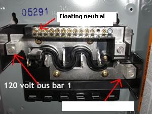
I would do the load (black) to the back bone.. and neutral (white) to the floating (on plastic) neutral bar.. and the ground to the ground bar which is flat on the metal casing (not shown in pic)..?? (this would be with 14/3 wire to a 5-20 type plug that would plug into the inverter front socket..)
and as long as all my outlets are wire LIKE THIS (all separate) I should be fine and not have to remove the GFI outlet??
Keep in mind I am offgrid and this in effect is my LOAD panel... nothing coming in from ANY grid..
Granted the OP in this post is apparantly similar but has a generator and Xfer switch.. so what ever you tell me to do may not apply to his issue.. -
Re: Frustrated-a fairly long post :-(
It is not the generator as it was not connected when I connected the inverter directly to the cord used by the generator. The panel is used is a small 30 amp square D QO48M30DSGP "Generator Panel". My inverter is the Cotek SK 1000 model page 20 of the manual states
3-6. AC Safety Groundingj
The AC output ground wire should go to the grounding point for your loads ( for example, a istribution panel ground bus ).
3-6-1. Neutral Grounding (GFCI’S)j
3-6-1-1. 120V modelsjThe neutral conductor of the AC output circuit of the Inverter is automatically connected to the safety ground during inverter operation. This conforms to National Electrical Code requirements that separately derived from AC sources (such as inverters and generators) which have their neutral conductors tied to ground in the same way as the neutral conductors from the utility tied to ground at the AC breaker panel. For models configured with a transfer relay, while AC utility power is present and the Inverter is in bypass mode, this connection (the neutral of the Inverter’s AC output to input safety ground) is not present so that the utility
neutral is only connected to ground at your breaker panel, as required. Here is a link to the manual that was provided with the inverter.http://midsummerenergy.co.uk/pdfs/cotek-sk-series-inverters-manual.pdf -
Re: Frustrated-a fairly long post :-(
look to page 21 of this manual version for wiring diagram. not in previous link
http://www.skingcompany.com/downloadfile.aspx?name=ST_Series_Manual_Jan2011.pdf
hth
KID #51B 4s 140W to 24V 900Ah C&D AGM
CL#29032 FW 2126/ 2073/ 2133 175A E-Panel WBjr, 3 x 4s 140W to 24V 900Ah C&D AGM
Cotek ST1500W 24V Inverter,OmniCharge 3024,
2 x Cisco WRT54GL i/c DD-WRT Rtr & Bridge,
Eu3/2/1000i Gens, 1680W & E-Panel/WBjr to come, CL #647 asleep
West Chilcotin, BC, Canada -
Re: Frustrated-a fairly long post :-(
So in my scenerio (not the OP).. and using that drawing on page 21..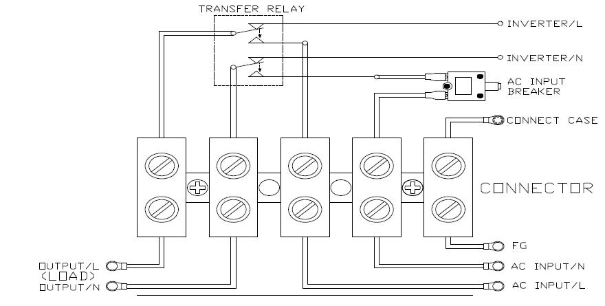
No generator or transfer relay.. and just an inverter to the load panel to the outlets..
I would use NEUTRAL/W and LOAD/B wires to the panel from the inverter GFI outlet.. and ground the inverter separate from the load panel ground (as that is the AC ground as well as DC ground for the inverter).. that sound about right??
The panel would have its own ground stake also.. -
Re: Frustrated-a fairly long post :-(
ywhic,
Are you suggesting to float the inverter/panel ground from the rest of the system? If so I would have safety concerns with this. What if there was a fault and someone got across both grounds? What if rain/moisture got on the panels or inverter, forms a ground and the GFI trips? What if there was a current leak in the inverter and the case becomes hot?
The GFI would be operating the same as a 2 wire GFI and just detecting a mismatch between hot and neutral. It would not be able to detect a potential neutral to ground problem (if the GFI is of that type). -
Re: Frustrated-a fairly long post :-(
Got the breaker on the neutral line instead of hot.
If you're going to switch loads between two sources, each of which have a neutral-ground bond, you need need to switch all three: hot, neutral, and ground.
The other choice is to remove the neutral-ground bond from both sources (including the one inside the inverter) and place it at the load distribution point only.
Either of these will remove the scenario where there are two neutral-ground bonds allowing a path around the neutral detection side of the GFI that causes the tripping. -
Re: Frustrated-a fairly long post :-(CATraveler wrote: »ywhic,
Are you suggesting to float the inverter/panel ground from the rest of the system? If so I would have safety concerns with this. What if there was a fault and someone got across both grounds? What if rain/moisture got on the panels or inverter, forms a ground and the GFI trips? What if there was a current leak in the inverter and the case becomes hot?
The GFI would be operating the same as a 2 wire GFI and just detecting a mismatch between hot and neutral. It would not be able to detect a potential neutral to ground problem (if the GFI is of that type).
I am asking.. not telling??
I'd like input as well.. I don't have the inverter yet.. does anyone have one the disected to fix this issue?? anyone remove the GFI or 'neutral-ground bond pair'.. or is it just take the GFI out the inverter, put in a std outlet, run the wire to the panel... and then just put GFI's on the outlets?? -
Re: Frustrated-a fairly long post :-(I am asking.. not telling??
I'd like input as well.. I don't have the inverter yet.. does anyone have one the disected to fix this issue?? anyone remove the GFI or 'neutral-ground bond pair'.. or is it just take the GFI out the inverter, put in a std outlet, run the wire to the panel... and then just put GFI's on the outlets??
Merely changing the outlet may not be enough if the internal neutral-ground bond is not actually on the outlet.
Keep in mind these inverters with built-in outlets are meant to be "end use", not wire to an AC distribution system. In their intended application they work fine. The problem arises when they are connected to a system that has its one N-G bond, which creates the dreaded ground loop. -
Re: Frustrated-a fairly long post :-(Cariboocoot wrote: »Merely changing the outlet may not be enough if the internal neutral-ground bond is not actually on the outlet.
Keep in mind these inverters with built-in outlets are meant to be "end use", not wire to an AC distribution system. In their intended application they work fine. The problem arises when they are connected to a system that has its one N-G bond, which creates the dreaded ground loop.
So if my new install of outlets and 'panel' has NONE then I should technically be fine and GTG.. and it will all fall on the GFI of the inverter correct.. like a big 'outlet strip' basically. -
Re: Frustrated-a fairly long post :-(So if my new install of outlets and 'panel' has NONE then I should technically be fine and GTG.. and it will all fall on the GFI of the inverter correct.. like a big 'outlet strip' basically.
Yes. The only problem then would be if you have a secondary power input: it will have no N-G bond. You can't use the one in the inverter (by switching only the hot) because the neutral line will go through the GFI. Guess what can happen then? Yep; some current can flow through that, trip the GFI, and disconnect the loads from the N-G bond inside the inverter.
Bit of a pain in the anatomy. -
Re: Frustrated-a fairly long post :-(Cariboocoot wrote: »Yes. The only problem then would be if you have a secondary power input: it will have no N-G bond. You can't use the one in the inverter (by switching only the hot) because the neutral line will go through the GFI. Guess what can happen then? Yep; some current can flow through that, trip the GFI, and disconnect the loads from the N-G bond inside the inverter.
Bit of a pain in the anatomy.
No secondary input possible on this system.. just the PV array, battery bank, and inverter.. thats it for my cabin..
I just want a 'panel' to bring all the outlets together neatly and somewhat proper looking.. vs have extension cords across the entire shed/cabin.. Going to put 2- 15 amp breakers in a mini 30 amp box and run a few circuits.. never draw more than the max anyway..
I'll put a note on the panel.. no secondary power source to be used on this system.. -
Re: Frustrated-a fairly long post :-(
That ought to work.


Categories
- All Categories
- 233 Forum & Website
- 140 Solar Forum News and Announcements
- 1.3K Solar News, Reviews, & Product Announcements
- 181 Solar Information links & sources, event announcements
- 894 Solar Product Reviews & Opinions
- 252 Solar Skeptics, Hype, & Scams Corner
- 22.5K Solar Electric Power, Wind Power & Balance of System
- 3.5K General Solar Power Topics
- 6.7K Solar Beginners Corner
- 1K PV Installers Forum - NEC, Wiring, Installation
- 2.1K Advanced Solar Electric Technical Forum
- 5.6K Off Grid Solar & Battery Systems
- 428 Caravan, Recreational Vehicle, and Marine Power Systems
- 1.1K Grid Tie and Grid Interactive Systems
- 656 Solar Water Pumping
- 816 Wind Power Generation
- 621 Energy Use & Conservation
- 623 Discussion Forums/Café
- 316 In the Weeds--Member's Choice
- 74 Construction
- 125 New Battery Technologies
- 108 Old Battery Tech Discussions
- 3.8K Solar News - Automatic Feed
- 3.8K Solar Energy News RSS Feed