Ground Fault White Paper by BB-Bill ??

Vic
Solar Expert Posts: 3,211 ✭✭✭✭
This paper used to be on the MidNite Forum AND here, IIRC.
There are Search hits at the MN Forum, but the Link is broken (this may just be due to several Server changes there, in the past ten years).
Cannot find it here, even using Google Searches, as a crutch.
Was it too controversial? OR ?? A lot of the early discussion still exists on the MN Forum, which is useful and probably adequate, as BB Bill was heavily involved on that Topic, way back then.
Idle "minds" are just curious. Thanks for any info, Vic
Off Grid - Two systems -- 4 SW+ 5548 Inverters, Surrette 4KS25 1280 AH X2@48V, 11.1 KW STC PV, 4X MidNite Classic 150 w/ WBjrs, Beta KID on S-530s, MX-60s, MN Bkrs/Boxes. 25 KVA Polyphase Kubota diesel, Honda Eu6500isa, Eu3000is-es, Eu2000, Eu1000 gensets. Thanks Wind-Sun for this great Forum.
Comments
-
Hi Vic,
Really want to "dig that one up" again?")
The paper is here:
https://us.v-cdn.net/6024911/uploads/attachments/512/1965.pdf
Note--Right after I made that PDF, my computer's hard drive crashed... I did not bother to resurrect the document as it pretty much said everything I wanted to say--And while I had a few engineers from other companies at the time contact me, the powers that be said I was talking about European regulations (not).
Our Forum discussion:
https://forum.solar-electric.com/discussion/9345/system-grounding
Midnite Forum Discussion:
http://midniteftp.com/forum/index.php?topic=142.0
Both sites have had hosting/URL changes (and Midnite users now manage the Midnite forum, not Midnite itself--I think).
-Bill
PS: I will post this in our FAQ section... It still comes up once a year or so... -BBNear San Francisco California: 3.5kWatt Grid Tied Solar power system+small backup genset -
Hi Bill,
Thank you very much for all of that info. Had found the Topic on the MN Fourm, but, the old Link to your paper was broken.
Thank you for ALL of your contributions !! Take care, VicOff Grid - Two systems -- 4 SW+ 5548 Inverters, Surrette 4KS25 1280 AH X2@48V, 11.1 KW STC PV, 4X MidNite Classic 150 w/ WBjrs, Beta KID on S-530s, MX-60s, MN Bkrs/Boxes. 25 KVA Polyphase Kubota diesel, Honda Eu6500isa, Eu3000is-es, Eu2000, Eu1000 gensets. Thanks Wind-Sun for this great Forum. -
You are very welcome Vic.And thank you for your help here too.BillNear San Francisco California: 3.5kWatt Grid Tied Solar power system+small backup genset
-
Bill,BB. said:Hi Vic,
Really want to "dig that one up" again?
The paper is here:
https://us.v-cdn.net/6024911/uploads/attachments/512/1965.pdf
Note--Right after I made that PDF, my computer's hard drive crashed... I did not bother to resurrect the document as it pretty much said everything I wanted to say--And while I had a few engineers from other companies at the time contact me, the powers that be said I was talking about European regulations (not).
Our Forum discussion:
https://forum.solar-electric.com/discussion/9345/system-grounding
Midnite Forum Discussion:
http://midniteftp.com/forum/index.php?topic=142.0
Both sites have had hosting/URL changes (and Midnite users now manage the Midnite forum, not Midnite itself--I think).
-Bill
PS: I will post this in our FAQ section... It still comes up once a year or so... -BB
reading through your white paper and must admit that most of it went right over my head. My cabin has no grounding as it was built at a time when the japanese did not run a third wire for ground purposes. The practice of requiring a ground wire started about 35 years ago here..my cabin is 45+ years old. So when I installed my solar I drove a grounding rod in next to my inverter and battery shed and ran a ground line from my solar panels to this ground as well as the grounds for solar controllers, inverters and battery ground (negative post to earth).
I no longer have grid power here so in reality I do not have to meet any code if I am not grid tied perse. However when I eventually replace the siding on the cabin I will have the wiring, sockets etc. replaced and brought to at minimum the current Japanese code but until then is there anything else you would recommend?
R/
Ken70kw LiFePo4 battery bank, 18 JA solar 200 watt panels, 20 sharp 200 watt panels, morningstar controller(s) and a magnum 4448 inverter with all the usual junk that goes with it. -
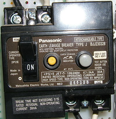
One option would be to install a RCBO main breaker, basically it's a whole house GFCI usually set to trip if there is a 30mA leakage line to ground, there are adjustable one as well, should a person become the leakage they will experience a slight shock for a milisecond of so but definitely not life threatening, this is the one I use because it's made for the distribution I have.

1500W, 6× Schutten 250W Poly panels , Schneider MPPT 60 150 CC, Schneider SW 2524 inverter, 400Ah LFP 24V nominal battery with Battery Bodyguard BMS
Second system 1890W 3 × 300W No name brand poly, 3×330 Sunsolar Poly panels, Morningstar TS 60 PWM controller, no name 2000W inverter 400Ah LFP 24V nominal battery with Daly BMS, used for water pumping and day time air conditioning.
5Kw Yanmar clone single cylinder air cooled diesel generator for rare emergency charging and welding. -
McIvor... just realized when looking at my panel it has a GFI main breaker but it looks nothing like that.
70kw LiFePo4 battery bank, 18 JA solar 200 watt panels, 20 sharp 200 watt panels, morningstar controller(s) and a magnum 4448 inverter with all the usual junk that goes with it. -
Ken, just out of curiosity... What voltage and line frequency will you be running (100 or 120 VAC, 50 or 60 Hz)?
Are you going to use/need two or three prong outlets (assume Japanese, mixing USA appliances)?
There are multiple reasons for grounds...- When you have two power leads (like 12 volts from a car battery) from a floating power source--You really should have ( two fuses--One for the + lead and a second for the - lead)--Floating supplies should have two fuses/breakers in the output (say 100 amps from battery is 2x 100 amp fuses, then if you have a 15 amps branch circuit, 2x fuses/breakers to the branch circuit). Doing worst case fault analysis--You can prove that a power system with multiple lower current branch circuits can overload wiring unless you have two fuses/breakers at each branch (the white paper was a version of showing a "floating" power systems with one fuse/breaker on each pair of power wires can cause big issues).
- If you "ground reference" one power lead (i.e., - 12 volt bus; white/neutral wire for 120 VAC USA wiring ground bonded), since that ground referenced lead never get above "zero volts" (really a few volts above zero)--Then you do not need to fuse/breaker "pairs" of power leads. Only the "Hot" lead needs a fuse/breaker, and the "Neutral/ground bonded" one does not).
- If you have a small AC power source (say 1,500 Watt AC inverter and 15 amp capable wiring "everywhere")--You really only need one fuse breaker on the AC out "hot wire" (and all else will be relatively safe from short circuits). If you have a 30 Amp AC output and send 15 amps to branch circuits (or whatever is standard in Japan)--Then you would have a "breaker or fuse" panel... 30 Amps in, and 15 amp branch circuits).
- Another reason for ground bonded AC neutral--Some AC florescent tube fixtures and spark ignition stoves need 120 VAC neutral+ground bonding to work correctly (in LED lighting, ground bonding not needed for operation).
- inpuGround bonding is also used when you have metal water pipes/sinks/fixtures as well as even propane stoves/heaters. You don't want a short to "metal" (sink, stove, plumbing) to make that "hot") as a source of power for electrocution to the person washing dishes, cooking, etc.... In the US, Water pipes (hot&cold, natural gas iron pipe, ground rod driven into ground) and metal electrical boxes are all connected together (common ground). If there is a short from "hot" to grounded metal, that completes the circuit and pops the fuse/breaker.
- If you are in a lightning prone area, grounding is very important. You want a direct path to ground (cold water pipe, ground rod) to send the lightning to earth.
In the US, for older homes that did not have ground wiring to sockets (just two wire sockets and no ground wire in walls--such as old Knob and Tube wiring)--A GFI outlet is an "acceptable" method to setup a "two wire" home to have "three wire" outlets. The GFI measures the current in/out on the two power wires, and if there is more than ~10-20 mAmps of "unbalance" (one lead found a path to ground--possible electrocution risk)--Then the GFI trips open.
A simple "hack" if you cannot find anything in Japan--A USA GFI Outlet would probably work fine:
https://www.homedepot.com/b/Electrical-Wiring-Devices-Light-Controls-Electrical-Outlets-Receptacles/GFCI/N-5yc1vZc33aZ1z17vh7?NCNI-5&searchRedirect=gfi&storeSelection=
These have two sets of terminals. One is the "AC input" (two wires). The output of the GFI goes to the outlet and has two more terminals (AC Out) that can go elsewhere (other outlets, etc.) and still be protected against GFI faults (GFI outlets have two buttons, Test and Reset). I don't think they will "care" if you are running 100 or 120 VAC 50/60 Hz. And they don't "need" a ground wire (on input or output side).
Some do have pilot lights (on=AC present)--May or may not like 90-100 VAC....
GFI's, many times, do not "like" MSW or square wave AC inverters (false trips possible). Work best with PSW/TSW inverters.
If you wire GFI's "everywhere"--I suggest that the ceiling lightning circuit not be on the same GFI circuit for the outlets. Don't want a simple GFI trip near sink to plunge the whole home into darkness (in USA, GFI protected outlets required near sinks, water, outside in new construction).
-BillNear San Francisco California: 3.5kWatt Grid Tied Solar power system+small backup genset -
Interesting link to various AC appliance plugs and outlets in Japan:
https://www.plugsocketmuseum.nl/Japan1.html
Older Japanese appliances that needed grounding has a separate ground wire that connected to a grounded thumb screw on/near socket (washer/dryer?).
Somebody said that there are RCB or RCD (residual current breaker/device) installed in the main power panel for homes (modern homes)--So that may be the way to address your question... RCB/D in "main panel" and power that with your solar/battery powered AC inverter....
-BillNear San Francisco California: 3.5kWatt Grid Tied Solar power system+small backup genset -
Bill power is currently 4kw from a magnum 4448 PAE inverter. later I will be paralleling a second inverter for a total of 8kw at 60 hertz 120/240 split phase.
when I first bought the cabin it had a GFI main breaker (RCB or RCD you mentioned) and 4 sub breakers, as it was tied to the Japanese grid. It is no longer tied to grid due to costs of upkeeping the grid in this area being passed directly to the customer. I unhooked last year when the power lines got blown down and TEPCO gave me a 10K estimate to repair my portion.... up till that point I had solar on my camper (10 years +) and the cabin was a part time thing I ran to reduce cost and act as a UPS for when power dropped
I will have to get photos later but I got a bigger box and moved the GFI main breaker into and added 4 breakers (total 8) ran new wires for my split pack and the coffin freezer. I just do not understand how the GFI works without a ground lead.... lightening took out my inverter last year, so I bought a bunch of the midnite solar SPD's both DC and AC versions, getting the DC wired in was a piece of cake, still have not figured out how to wire in the ac and get it to work. I do it according to the instructions and no lights in the SPD come on... still puzzling that out. so you think that the GFI breaker already installed is all I can do until I rewire?
here is the japanese GFI breaker
70kw LiFePo4 battery bank, 18 JA solar 200 watt panels, 20 sharp 200 watt panels, morningstar controller(s) and a magnum 4448 inverter with all the usual junk that goes with it. -
Regarding the Midnite SPDs... I am not sure why the blue LED is not lighting. They are pretty basic. Just one common wire (connect to ground)... The other two (L1 and L2) connect to your AC circuit(s). These are designed for North America 120/240 VAC split phase--So the two L1&L2 lines...
https://www.midnitesolar.com/pdfs/SPD_Installation_Manual.pdf
My guess why the LED is not lighting (assuming they are working correctly) is that you connect the green wire to ground and L1&L2 your black and white AC power wires (90-100 VAC line voltage?) to the SPD. If the incoming power is not ground referenced (in North America, the White wire is the Neutral and tied to the home ground bus--And usually also tied at the pole transformer to ground rod)--Then you have a floating AC power source, and no path from L1/L2 to Ground (the only path is from L1 to L2). I don't know what is/was standard for Japan--But their modern outlets seem to have a "wide blade" and is labeled "neutral"--So I would suspect that in Japan, modern homes have the White/Neutral connected to a cold water pipe and/or ground rod driven into the earth.
But you are off grid... So you need to go back to the Magnum Manual. It is a PSW/TSW (pure/true sine wave) inverter, and the basic documentation talks about Neutral--So ground bonding the Neutral should be just fine (always check the manual). (note: Black and White colors are Black/Red=Hot and White=Neutral--May not be true in Japan--Always verify).
https://www.solar-electric.com/lib/wind-sun/Magnum-MS-PAE-Manual.pdf
From reviewing the manual... You need to tie one of the White Wire/AC Neutral to Ground. In the USA, that is normally done in the main breaker panel (and, of course, the ground bus needs to connect to the cold water pipe / ground rod / etc.).
I don't know if in Japan you have 120/240 VAC "split phase" power, or just 90/100/110 VAC only to your panel... Your Inverter is 120/240 VAC split phase--So the USA breaker panels have two (L1 and L2) bus bars--And you can pull 120 or 240 VAC from the panel.
If in Japan you only have single phase (One "hot" bus bar+breakers and one "neutral" bus bar, then you would have to wire up two AC "main panels" at 120 VAC each (L1+White to one, and L2+White to second). And in either panel, connect White/Neutral to Ground bus bar (of course, "grounds" need to be run to both panels).
If you run L1+Neutral to the homes RCB to Main panel--You will not have the other L2+neutral power available (reduced AC inverter output, no 240 VAC available). In the case of using the RCB, you will need to Ground Bond the Neutral "before" the RCB. (if you ground bond after the RCB, you can get false RCB trips).
If you want to stay "Japan style" for wiring with single phase panels... Then you could wire up L1+N to your existing RCB + main panel... And install a second RCB + Main panel for L2+N. (again ground bond neutral "before" RCBs).
At this point, following North American wiring standards using local hardware as you can fit seems to be the best course of action.
If you are now more confused--Just ask to clarify. There are a lot of open questions (100 VAC only, 100/200 VAC split phase power, Japan code for Neutral+Ground bonding, use of RCB, etc.).
The use of an RCB seems to indicate that Japan either does not Neutral Bond, or does not keep track of Black/White Hot/Neutral (unpolarized wiring).
In the USA, >=25 mAmp GFI is used for industrial equipment... For standard 15 amp branch circuits, ~5 mAmp GFI trip-point units are used. Just more sensitive, and better suited to reduce electrocution risk (more or less, >10 mAmps is enough to stop a heart). The 30 mAmp RCB would be better suited to be the "fault to ground" short circuit prevention (actual short circuit). And RCB at input to main panel, again seems to be a "fix" for shorts to grounds with only one breaker on the AC circuit (vs two breakers "required" for floating power supplies).
If you are concerned about electrocution... You can always install GFI breakers/outlets on individual branch circuits. The GFI outlets from USA should work fine. And there are GFI/Arc Fault breakers (for USA circuit panels):
https://images.thdstatic.com/catalog/pdfImages/c5/c52dc029-293c-4a07-b6db-c60bdaf507a7.pdf
Note that 1) Arc Fault breakers can be a pain... They are known to false trip when you use, for example, a vacuum cleaner with brushed motor (not often, but has been an issue for a few folks). Also, they need to have a neutral wire run to the breaker then Load+Neutral to the branch circuit (so breaker can measure leakage current).
You ask how does a GFI work, especially without a ground wire... They are really neat and simple. The basic electrical AC electrical circuit, the current flows out one wire, and back on the return (and alternates 50/60 times a second). If you send the "pair" of AC wires through a transformer as the "primary" winding. And the second winding is the 5 mAmp sense leads. Since a good circuit, the +/- Current Flow cancels each other, then there is "zero" net current flow in the "current" transformer, and the sense leads see zero current. However, if there is an >0.005 amp leak from Black (or white) wire to a different path (say to ground), the +/- wiring current flow is different, so the transformer picks that up and outputs it to the sense leads which trip the GFI device.
https://www.gt-engineering.it/en/Insights/nec-and-the-gfci
-BillNear San Francisco California: 3.5kWatt Grid Tied Solar power system+small backup genset -
Bill you are a full blown treasure trove of info and the forum is lucky to have you mucking about. so in order of appearance:BB. said:Regarding the Midnite SPDs... I am not sure why the blue LED is not lighting. They are pretty basic. Just one common wire (connect to ground)... The other two (L1 and L2) connect to your AC circuit(s). These are designed for North America 120/240 VAC split phase--So the two L1&L2 lines...
https://www.midnitesolar.com/pdfs/SPD_Installation_Manual.pdf
My guess why the LED is not lighting (assuming they are working correctly) is that you connect the green wire to ground and L1&L2 your black and white AC power wires (90-100 VAC line voltage?) to the SPD. If the incoming power is not ground referenced (in North America, the White wire is the Neutral and tied to the home ground bus--And usually also tied at the pole transformer to ground rod)--Then you have a floating AC power source, and no path from L1/L2 to Ground (the only path is from L1 to L2). I don't know what is/was standard for Japan--But their modern outlets seem to have a "wide blade" and is labeled "neutral"--So I would suspect that in Japan, modern homes have the White/Neutral connected to a cold water pipe and/or ground rod driven into the earth.
But you are off grid... So you need to go back to the Magnum Manual. It is a PSW/TSW (pure/true sine wave) inverter, and the basic documentation talks about Neutral--So ground bonding the Neutral should be just fine (always check the manual). (note: Black and White colors are Black/Red=Hot and White=Neutral--May not be true in Japan--Always verify).
https://www.solar-electric.com/lib/wind-sun/Magnum-MS-PAE-Manual.pdf
From reviewing the manual... You need to tie one of the White Wire/AC Neutral to Ground. In the USA, that is normally done in the main breaker panel (and, of course, the ground bus needs to connect to the cold water pipe / ground rod / etc.).
I don't know if in Japan you have 120/240 VAC "split phase" power, or just 90/100/110 VAC only to your panel... Your Inverter is 120/240 VAC split phase--So the USA breaker panels have two (L1 and L2) bus bars--And you can pull 120 or 240 VAC from the panel.
If in Japan you only have single phase (One "hot" bus bar+breakers and one "neutral" bus bar, then you would have to wire up two AC "main panels" at 120 VAC each (L1+White to one, and L2+White to second). And in either panel, connect White/Neutral to Ground bus bar (of course, "grounds" need to be run to both panels).
If you run L1+Neutral to the homes RCB to Main panel--You will not have the other L2+neutral power available (reduced AC inverter output, no 240 VAC available). In the case of using the RCB, you will need to Ground Bond the Neutral "before" the RCB. (if you ground bond after the RCB, you can get false RCB trips).
If you want to stay "Japan style" for wiring with single phase panels... Then you could wire up L1+N to your existing RCB + main panel... And install a second RCB + Main panel for L2+N. (again ground bond neutral "before" RCBs).
At this point, following North American wiring standards using local hardware as you can fit seems to be the best course of action.
If you are now more confused--Just ask to clarify. There are a lot of open questions (100 VAC only, 100/200 VAC split phase power, Japan code for Neutral+Ground bonding, use of RCB, etc.).
The use of an RCB seems to indicate that Japan either does not Neutral Bond, or does not keep track of Black/White Hot/Neutral (unpolarized wiring).
In the USA, >=25 mAmp GFI is used for industrial equipment... For standard 15 amp branch circuits, ~5 mAmp GFI trip-point units are used. Just more sensitive, and better suited to reduce electrocution risk (more or less, >10 mAmps is enough to stop a heart). The 30 mAmp RCB would be better suited to be the "fault to ground" short circuit prevention (actual short circuit). And RCB at input to main panel, again seems to be a "fix" for shorts to grounds with only one breaker on the AC circuit (vs two breakers "required" for floating power supplies).
If you are concerned about electrocution... You can always install GFI breakers/outlets on individual branch circuits. The GFI outlets from USA should work fine. And there are GFI/Arc Fault breakers (for USA circuit panels):
https://images.thdstatic.com/catalog/pdfImages/c5/c52dc029-293c-4a07-b6db-c60bdaf507a7.pdf
Note that 1) Arc Fault breakers can be a pain... They are known to false trip when you use, for example, a vacuum cleaner with brushed motor (not often, but has been an issue for a few folks). Also, they need to have a neutral wire run to the breaker then Load+Neutral to the branch circuit (so breaker can measure leakage current).
You ask how does a GFI work, especially without a ground wire... They are really neat and simple. The basic electrical AC electrical circuit, the current flows out one wire, and back on the return (and alternates 50/60 times a second). If you send the "pair" of AC wires through a transformer as the "primary" winding. And the second winding is the 5 mAmp sense leads. Since a good circuit, the +/- Current Flow cancels each other, then there is "zero" net current flow in the "current" transformer, and the sense leads see zero current. However, if there is an >0.005 amp leak from Black (or white) wire to a different path (say to ground), the +/- wiring current flow is different, so the transformer picks that up and outputs it to the sense leads which trip the GFI device.
https://www.gt-engineering.it/en/Insights/nec-and-the-gfci
-Bill
I now believe that I have a bad SPD out of the box. all the rest of the SPD's on the DC side work fine. I hooked it up to L1 L2 and the neutral/ground in the breaker box like all the videos on you tube (and the manual suggests) I was just worried I had screwed it up... no worries i have another on order and this (if warranty replaces) will be a spare.. or possibly in the box in the house just for general purposes.
I drove a ground rod and created a ground that is bonded (attached) to neutral in my power box. genset was originally bonded but
my power for house when on solar is 120/240 split phase from the inverter.
when I use the genset it droops a little depending upon load genset for soalr etc. is 5Kw Makita US version 120/240 split phase but its the older type sold in the states its not as clean as newer inverter units, but its specs are pretty good for its age (found new in box at a japan wharehouse.) have no clue what they were thinking when they reverse imported it. didn't matter to me..price was right and its US spec. good thing about the magnum I could (and had in the past) hooked it up to a japanese spec 6Kw split phase and it worked fine albet at a slightly lower voltage 100/200 split phase
the newer houses are fully grounded just like in the states.. my cabin is just old and pre current specs. I will remedy that when I rip off the siding and can easily run new wiring to new Japan specs which seem same as UL specs for fusing, grounding, and wire/cabling requirements.
I am obviously not an electrician.. just not smart enough to leave well enough alone if the local contractors were a little more reasonably priced I would gladly pay someone else to do most of this for me. though from what I have seen I have almost as much knowledge in regards to solar as they seem to have. and am rapidly gaining ground in regards to general AC power issues thanks to this and several other forums I have been bouncing around at. I just do not have the training at times to understand some of the nuances that you have obviously soaked up over the years.. be it trade school, college or just experience you are a very valuable asset to this forum and DIYer's in general 70kw LiFePo4 battery bank, 18 JA solar 200 watt panels, 20 sharp 200 watt panels, morningstar controller(s) and a magnum 4448 inverter with all the usual junk that goes with it. -
The Makita genset is probably fine... The plain old vanilla alternator based gensets (not inverter-generator) are usually pretty good from major manufacturers.
The usual issues are 1) if you have a large "non-linear" load such as a large battery charger or Computer power supply, these take Line Current from the 'peak' of the AC sine wave--And can "slice" the top off off. Larger gensets (like yours) are typically not badly affected.
2) issue is frequency stability... Mechanical governors can be off on RPM. "Good" frequency is usually less than +/- 1 Hz... "Bad" frequency is > +/- 5 Hz. Some inverter-chargers and electronic battery chargers can have frequency limits and no "sync" with the genset if the line frequency or voltage is too far off (some are programmable). Many Kill-a-Watt type power meters have frequency reading. And the "fancier" DMMs (digital multi-meters) do too.
For some folks, they have "sync" problems with their genset when first starting. A common method is to put a small AC load on the genset to "stabilize" frequency and line voltage. Using a couple 100 filament lamps (if you can find those any more) or a small electric heater is a quick check to see if genset is working correctly or not.
Thank you for the complements on my attempts at explaining electrical stuff... I used to take a lot of things apart when I was a kid to see what made them tick (I and my father were not always able to put them back together ). I have a "general" engineering degree (not an EE specifically)--So I got a lot of different classes on EE, mechanical, thermal, etc... I really enjoy "systems" (computer, electro/mechanical/and even documentation systems). I have always been able to group "things" as black boxes (guess at how something probably does work)--And then put them together in a system (i.e., invert-charger+solar+genset, etc.) and quickly figure out when something was not "playing well" with other black boxes. I try not to get wrapped up in the details when looking at systems. works 90% of the time--And the 10% it does not work, then have to do the hard work looking a black box in detail.
For generators/inverters--This website has a lot of information and is very readable. Answers many of the questions about the system components/details for off grid power and the "issues" with AC power:
http://www.screenlightandgrip.com/html/emailnewsletter_generators.html
-BillNear San Francisco California: 3.5kWatt Grid Tied Solar power system+small backup genset

Categories
- All Categories
- 233 Forum & Website
- 140 Solar Forum News and Announcements
- 1.3K Solar News, Reviews, & Product Announcements
- 181 Solar Information links & sources, event announcements
- 894 Solar Product Reviews & Opinions
- 252 Solar Skeptics, Hype, & Scams Corner
- 22.5K Solar Electric Power, Wind Power & Balance of System
- 3.5K General Solar Power Topics
- 6.7K Solar Beginners Corner
- 1K PV Installers Forum - NEC, Wiring, Installation
- 2.1K Advanced Solar Electric Technical Forum
- 5.6K Off Grid Solar & Battery Systems
- 428 Caravan, Recreational Vehicle, and Marine Power Systems
- 1.1K Grid Tie and Grid Interactive Systems
- 656 Solar Water Pumping
- 816 Wind Power Generation
- 621 Energy Use & Conservation
- 623 Discussion Forums/Café
- 316 In the Weeds--Member's Choice
- 74 Construction
- 125 New Battery Technologies
- 108 Old Battery Tech Discussions
- 3.8K Solar News - Automatic Feed
- 3.8K Solar Energy News RSS Feed