Pure sinewave inverter motherboard control board/fet issue?

Comments
-
I do not know these particular boards.
However our OzInverter is using the 8010 PWM chip, and 3 flashes and a gap of 2 seconds means that the control board is seeing overvoltage either from a faulty transformer or with its own PSU + or - 5v for the control board.
We found that the EGS002 board to be a poor design, especially around the op amp arrangements that use the 8010 pin 6 start and stop method.
So we redesigned, and we just used the 8010 PWM chip only, and built a more substantial and better quality control board for our OzInverter.
We also found that the EGS002 would really flake out above 2.5kw with a toroid transformer.
The 8010 chip has a good soft start process that suits our more efficient toroid transformer that we use in the OzInverter, but even so some 8010's chips we have examined have certain operating details missing in their original programming..
I also understand that Quality control with individual components is also a big issue with these boards , especially around the Caps, IR2110 Driver chips and poor quality FET's.
Those EGS002 boards are very cheap to buy at only a few dollars, so try a swap out.
I trust this helps.Everything is possible, just give me Time.
The OzInverter man. Normandy France.
3off Hugh P's 3.7m dia wind turbines, (12 years running). ... 5kW PV on 3 Trackers, (8 years) .... 14kW PV AC coupled using Used/second hand GTI's, on my OzInverter created Grid, and back charging with the AC Coupling and OzInverter to my 48v 1300ah batteries.
-
Would your redesign control driver board possible can work with my motherboard..if yes how can I get it to.purchase?
-
What do u mean by flake out above 2.5kw?We also found that the EGS002 would really flake out above 2.5kw with a toroid transformer.
I have a toroid (donut shape) transformer using with the control board
So i wonda if that is the issue as to why the fets got damage. What can I do to prevent future occurrence?
-
No, Our control board will only work with our big power board.
However, our control board can be a direct swap in for a Power Jack control board, but that depends on which one?. Please note ... 'Power Jack' like other Chinese companies are constantly upgrading and changing, and not necessary for the best, so their products today might mean that our control board may not function. Power jack also have some terrible QC issues.
A toroid transformer although far more efficient than a standard individual laminate sheet type, also has some surge issues and can put the FET's under severe stress, and i doubt that your board has been designed for robustness.
Looking at your board i would say that 1kw is a probable output, but having a overlarge toroid may have stressed your board.
Our OzInverter was designed for full time running up to 6kw all day if you want, 15 minutes or so at 12kW and surges up to 50kW, but at the same time only consume 30 to 40 watts in running. Also the OzInverter is a H bridge design so AC coupling can be operated from its AC output and go into reverse and change that AC coupling Grid tied Inverter output into DC and charge the batteries.
We were never happy with the commercial Inverters on the market, even the supposedly Rolls Royce of Inverters, that gave misleading information or insufficient information about their products.
So hence we designed and built our own, that is simple, robust and very cost effective.
We do an assembly book, now a 2nd edition, which also contains all the boards design layouts and how to make your own toroid etc. and we can also supply the Power Board, Control board and the cooling board, all of these boards are through hole components except the 8010 chip which is on its own SMD plug in daughter board, and designed with special FET gates and large tracks and large solder pads to avoid track laminate separation.
I have listed this OzInverter book on this forum.
I will also take this opportunity to give a WARNING...... Some electronic folk seem to think that you can mix and match components with large powerfull Inverters, ..... YOU CAN NOT.! In the OzInverter book all the parts of the making of the Ozinverter are shown, and instructions should be followed implicitly. All Powerful Inverters are Power Electronics with heavy cabling and especially designed circuits to match. Using an insufficient cable from the DC source to the FET's heatsink can put those FET's under immense stress, ie voltage Sag. And very easy to melt/splat a 8mm bolt with a 500 amp mili second capacitor surge.
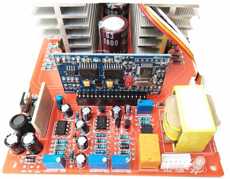
Here is the OzInverter boards.......


Everything is possible, just give me Time.
The OzInverter man. Normandy France.
3off Hugh P's 3.7m dia wind turbines, (12 years running). ... 5kW PV on 3 Trackers, (8 years) .... 14kW PV AC coupled using Used/second hand GTI's, on my OzInverter created Grid, and back charging with the AC Coupling and OzInverter to my 48v 1300ah batteries.
-
The controller board that I have is the red one and it has a jumper wire running from it to the main board. I realize that I am.not seeing anymore of the red boards on the.net selling. Is just the blue boards I am.seeing and seeing them connected to.the mainboard there is no jumper wire connected to them. So.I am wondering if I replace my red board with the blue board would u suggest that I place the jumper wire on it also? I am.thinking probably the blue board is a upgrade from the red board so therefore the jumper wire is not needed.
What do u suggest I do? -
Sorry, i can not help you any more with your boards.
As I have already said, I do not know these boards that you are using.Everything is possible, just give me Time.
The OzInverter man. Normandy France.
3off Hugh P's 3.7m dia wind turbines, (12 years running). ... 5kW PV on 3 Trackers, (8 years) .... 14kW PV AC coupled using Used/second hand GTI's, on my OzInverter created Grid, and back charging with the AC Coupling and OzInverter to my 48v 1300ah batteries.
-
I got some help on a next Web page.
Read what I wrote at the bottom and tell me what you think please.
https://www.fieldlines.com/index.php/topic,150230.0.html
-
Oztules and myself disregarded the EGS002 but retained the 8010 chip and with that we just circumnavigated any problems we came across and just redesigned a new Inverter.
'Podia' and 'noneyabussiness' really examined the original problems with the EGS002 and came up with solutions.
As I said, I have no experience with your boards, but 'noneybuissness' does with the 24 FET version, so go with his suggestions.Everything is possible, just give me Time.
The OzInverter man. Normandy France.
3off Hugh P's 3.7m dia wind turbines, (12 years running). ... 5kW PV on 3 Trackers, (8 years) .... 14kW PV AC coupled using Used/second hand GTI's, on my OzInverter created Grid, and back charging with the AC Coupling and OzInverter to my 48v 1300ah batteries.
-
zener diodes are not the same as a TVS and will disappoint, along with your other shortcuts.
Powerfab top of pole PV mount | Listeroid 6/1 w/st5 gen head | XW6048 inverter/chgr | Iota 48V/15A charger | Morningstar 60A MPPT | 48V, 800A NiFe Battery (in series)| 15, Evergreen 205w "12V" PV array on pole | Midnight ePanel | Grundfos 10 SO5-9 with 3 wire Franklin Electric motor (1/2hp 240V 1ph ) on a timer for 3 hr noontime run - Runs off PV ||
|| Midnight Classic 200 | 10, Evergreen 200w in a 160VOC array ||
|| VEC1093 12V Charger | Maha C401 aa/aaa Charger | SureSine | Sunsaver MPPT 15A
solar: http://tinyurl.com/LMR-Solar
gen: http://tinyurl.com/LMR-Lister , -
mike95490 said:zener diodes are not the same as a TVS and will disappoint, along with your other shortcuts.
With this in mind its best to remove my exisiting 1n4148 diodes on the mainboard and install the diodes that he suggested?
-
For the Ozinverter FET gates we use fast diode IN5819, a 0.6w 20k and a 0.6w 5r6 resistors very close to the FET. We use IRB4110 or HY4008 FET's.


The HY4008 FETS in the above photo are not yet soldered. But Please remember that our Power board and our control board were designed to match.
Alot of thought and testing went into the boards for fast and matched operation and reducing ground loops and reducing Parasitic frequency's, and at the same time to be easy to assemble and ease of repairs later if needed. (Note, after a few years of running Moths are drawn to the LED's and large moths have a habit of touching things they shouldn't), so i recommend conformal coating after a period of testing. For driving our FETS we use 15volt IR2110 drivers.
'noneyabuisness ' has a working board similar to yours, so try liaising and talking to him.Everything is possible, just give me Time.
The OzInverter man. Normandy France.
3off Hugh P's 3.7m dia wind turbines, (12 years running). ... 5kW PV on 3 Trackers, (8 years) .... 14kW PV AC coupled using Used/second hand GTI's, on my OzInverter created Grid, and back charging with the AC Coupling and OzInverter to my 48v 1300ah batteries.
-
So given in mind that my main board has 8 fets. I can add 8 of the TVS Diode on each of the fet gates?
Also my control board maybe faulty now with the issue that I mention in the first post. If I do the mod to.it instead of waiting for.the new control.board. Chances are it might fix the no.output issue I am getting from the inverter?
-
my original board is red colour one so with the new replacement one which is the blue board chances are that it is an upgrade to the red one hence it doesn't require any mods and the resistor that runs from the mainboard to the original red board wouldn't be valid for the blue board so I don't have to solder it to the blue board with or without any modification being done to the board.
-
I recently got the new control board and install it and when i turn on the inverter i am getting the same relay clicking sound and multiply flashes from the led lights on both the main and control board and then afterwards all of that comes to a stop and then i am getting a 4 flash sequence from the led lite on the control board with a 2 sec pause between the 4 flashes and also there is a momentary humming from the transformer which i assume is because some form of dead shorts is happening on the board but when i check the mosfets legs there are no continuity between each legs and my input and output fuse have not been blown.When you just turn on the inverter there is slow rise of the ac voltage to around 38v because the board was set to soft start by default. and then then afterwards the tester starts to beep constantly showing continuity between the output L and N.I am now wondering if i should replace all 8 fets because when the fets got damage, only 6 burst so i replaced 6 instead of 8.Or is it the case that the transformer got burned hence that it why i am getting the humming sound from it every now and then, even thou i don't see or smell any form of burn evidence.What do you suggest i do?
-
Part 3 of the modification states:
"The choke:
Find a suitable and large ferrite E core.
I used one of these
https://au.rs-online.com/web/p/products/8407648/
stock no. 840-7648
It has a 0.5mm gap. Wiseguy correctly pointed out in another post of yours
my incorrect calculations.
Other people here have made their own, in different ways, using different cores.
We need something like 45uH, and the inductor (or choke) needs to still
work with currents well over 100A if you are planning to put 5000W through a 48V inverter"
In regards to the above statement. I have already bought a inductor that lowers the idle current that the website where i bought the mainboard recommended to use with the board and i connected it to the mainboard and everything was working quite fine until the mosfets got damage. Do I still need to get the choke as he suggested in part 3 of the modification or i can just use the existing inductor that i have and skip out part 3 of the modification?
-
for part 2 of the modification can someone show me where to connect the 15v tvs diodes to the bottom of my circuit board. I am kinda confuse. i bought 10 of them online as i dont quite sure where each of them should go and how much to use. my board uses 8 fets. i uploaded a photo below with the bottom of the board. i would love to get a diagram showing exactly where each diode should go on my board.please explain in details how to do it.

-
The way to do it, is to sign up for year 1, 2 & 3 electronics courses at your local collage. Sorry. Someone has to say it.
You are out of your league and while I appreciate your ambition, you are not headed for success. FET repair is way more than just swapping parts, drivers usually blow with the FETs and you still have not diagnosed the original reason they blew, I don't think.
Powerfab top of pole PV mount | Listeroid 6/1 w/st5 gen head | XW6048 inverter/chgr | Iota 48V/15A charger | Morningstar 60A MPPT | 48V, 800A NiFe Battery (in series)| 15, Evergreen 205w "12V" PV array on pole | Midnight ePanel | Grundfos 10 SO5-9 with 3 wire Franklin Electric motor (1/2hp 240V 1ph ) on a timer for 3 hr noontime run - Runs off PV ||
|| Midnight Classic 200 | 10, Evergreen 200w in a 160VOC array ||
|| VEC1093 12V Charger | Maha C401 aa/aaa Charger | SureSine | Sunsaver MPPT 15A
solar: http://tinyurl.com/LMR-Solar
gen: http://tinyurl.com/LMR-Lister , -
I change out the fets and the control board and it is working quite fine now i just need to do the modification on the control board thats why i am asking for the assist.
-
So basically i need to install a total of 4 in all?
On the bottom of the board i notice that on each side of the board 2 mosfets source pin or connected and then on the same side of the board there are another 2 mosfets that shows that the 2 source pins are connected too.
So when installing the tvs diodes should i place the white line to connect to one set of the mosfets which means the white line would connected to both gates of the set of mosfets or just one gate of any one of them and then the black part connected to the source pin and i repeat this for the other section on the same side of the board which the other 2 mosfets source pins are connected as one?
If i am not sure how to do it, would placing one diode for each mosfet have any negative effect or cause any issues on the board?
-
The board is working ok but today i just discovered an issue.
My transformer is by default a 220vac split phase one with 110vac on each hot leg but i abandon one of the hot legs and was just using one side which is just 110vac i was using up til today i decide to use the 220vac which is the 2 hot legs. When i went ahead an test the 2 hot legs i am only now getting 110vac and when i test the neutral and one of the hot i am getting basically 60vac on each leg.So in essence the transfomer as now decrease to 110vac split phase instead of 220vac split phase.It is strange because i have a little meter that comes with the control board and it is connected to the 7 pin slot on the control board and it is showing 220vac at 60hz. Is it because i change the frequency from 50hz to 60hz make i am only getting 110vac from the 2 hot legs?What could have cause this to happen? is it because of the modification i did on the board and on the control board or is it because of when i was buying the board i chose the option that ask about output voltage and i chose 110vac for the output even thou my transformer is rated for 220vac output? So probably the board came in output 110vac by default even thou the transformer is 220vac split phase it just ignore that and still produce just 110vac on each hot base upon some configuration on the board.When i test the primary stage/transformer input wires that goes to the board i am getting 8.6vac going to the board, shouldn't it be about 12-14vac going to the board? when i test the battery - with anyone of the transformer input wires i am getting 12.6vdc which is half of my battery voltage. I am confused guys.how can i remedy this issue?the board is working quite fine still because i am getting a well regulated 120vac on the output even under high 1KW+ wattage.is just that i would need back the 220vac capability that the transformer originally had.
Categories
- All Categories
- 233 Forum & Website
- 140 Solar Forum News and Announcements
- 1.3K Solar News, Reviews, & Product Announcements
- 181 Solar Information links & sources, event announcements
- 895 Solar Product Reviews & Opinions
- 252 Solar Skeptics, Hype, & Scams Corner
- 22.5K Solar Electric Power, Wind Power & Balance of System
- 3.5K General Solar Power Topics
- 6.7K Solar Beginners Corner
- 1K PV Installers Forum - NEC, Wiring, Installation
- 2.1K Advanced Solar Electric Technical Forum
- 5.6K Off Grid Solar & Battery Systems
- 428 Caravan, Recreational Vehicle, and Marine Power Systems
- 1.1K Grid Tie and Grid Interactive Systems
- 656 Solar Water Pumping
- 816 Wind Power Generation
- 621 Energy Use & Conservation
- 623 Discussion Forums/Café
- 316 In the Weeds--Member's Choice
- 74 Construction
- 125 New Battery Technologies
- 108 Old Battery Tech Discussions
- 3.8K Solar News - Automatic Feed
- 3.8K Solar Energy News RSS Feed