Frying 30A PWM Charge Controller

Hello,
Last year October, I purchased the Renogy 400W Solar Panel Mono Starter Kit, along 4 Duracell SLIGC115 6V batteries and a Power Brite 3500W MSW Inverter to use at our remote off grid cabin.
In the beginning everything worked great. We purchased a Vassani 9.9 cu ft refrigerator plugged into the inverter working flawlessly. The refrigerator pulls 329kWh per year. Over the winter period we lost power more frequently. Then we noticed that our original Renogy 30A PWM was not charging the batteries. We replaced with another brand 30A PWM, to find that the DC + (input) melted due to what seems like over current. At that time there was no fuse/break on that DC in line from the batteries to the DC + on the charge controller. Last week I then replaced the charge controller with another 30A PWM and installed a 30A breaker on the DC + line. Everything seemed to be going alright and charging was going up. What I noticed at that time is that with the sun going down, our voltage level on the batteries dropped quickly to 60%.
Upon arriving this past weekend, I noticed a red light on the battery status, over discharge, and the DC + was melted again, but the breaker did not trip. The batteries had not been charging and were again depleted to around 60% or below.
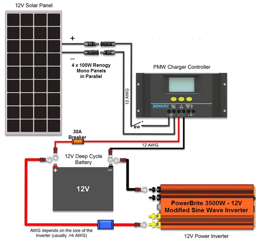
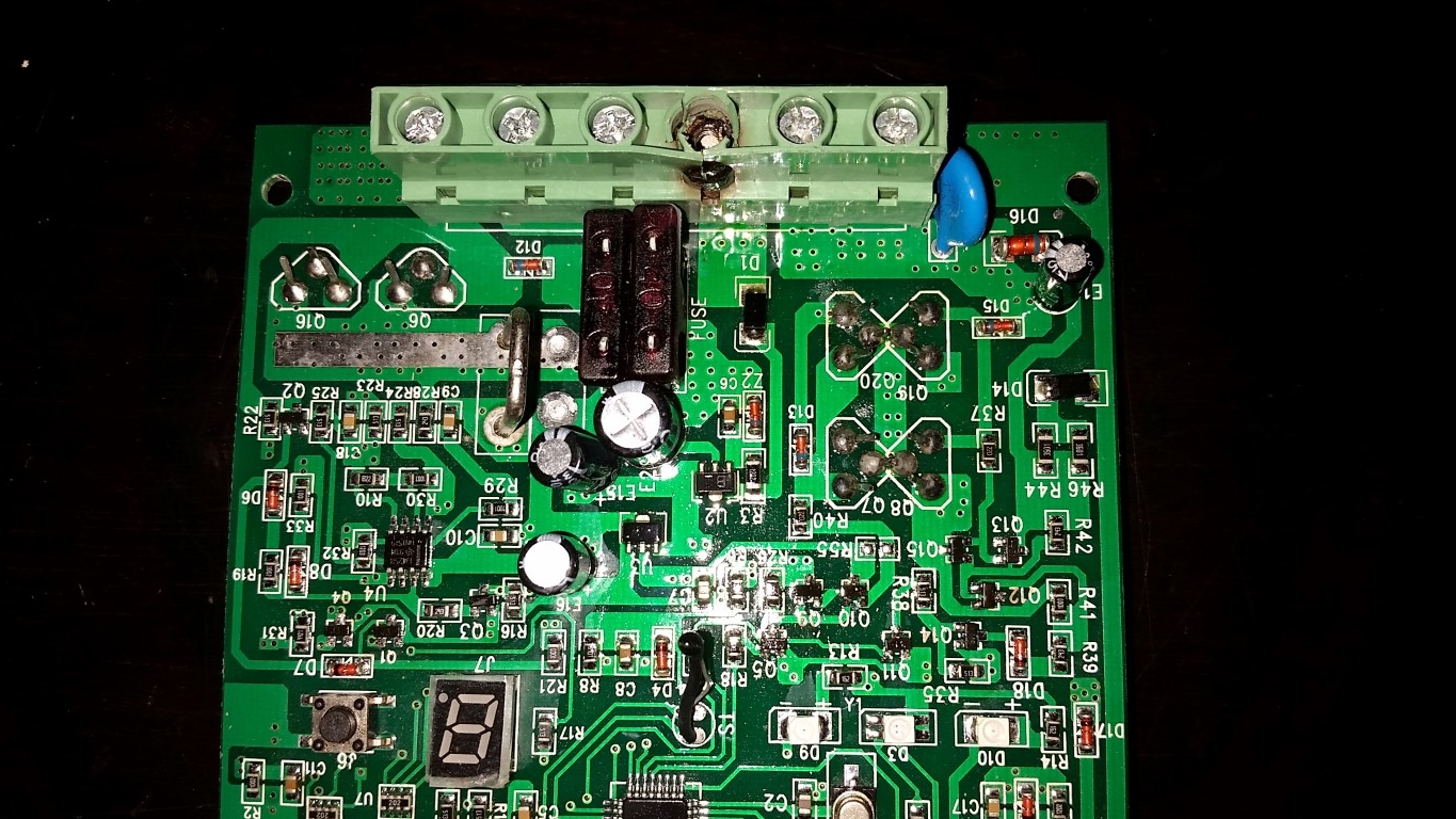
I have no idea what is giving the DC + input an over current, or melting, condition. Below is my configuration. Is there anything you can think of that would give me the problem of melting the DC Input? (see controller pictures below)
Solar Setup - 2016
(4) Renogy 100 Watt 12 Volt Monocrystalline Panels
- Parallel
- Less than 20 ft from Charge Controller
30A PWM Renogy Charge Controller
- 30A breaker on DC + input
- No fuse/breaker on Solar Panel + input
4 Duracell SLIGC115 6V @ 230AH
- Series and Parallel for 12V @ 460AH
Power Bright Power 3500 Watt 12V - Modified Sine Wave Inverter
- 200A Inline Fuse from battery to Invert + input
PWM 30A Charge Controller (DC + melted)
Any help would be greatly appreciated.
Comments
-
Hi tim..,
Thanks for posting the diagram and pic of the Charge Controller (CC).
Most often, these burned terminals are caused by a loose connection. Or, perhaps a horribly under-sized wire for the current flowing in the circuit. And, the same current should be flowing in the negative lead of the battery cable and at the negative battery terminal of the CC. Which might be a further indication of a loose connection at that burned terminal. However, there could be a situation where the battery negative and the PV negative are tied together outside of the CC which could, possibly, divide the negative output current between two terminals ... if the CC is not wired as shown in the diagram.
It is customary to torque connections, and re-torque them again in about 24 hours.
As an aside, MSW Inverters are often a poor choice for many applications, especially where they power motors ... AND, having a 3500 W inverter (of any kind) on a 12 V system is really not a good design choice. As the current demands on the batteries can be HUGE. Plus the amount of power consumed just to run the inverter (Tare or Idle power) on these inverters are often more than the average load that the inverter is trying to power.
It looks like you really should have more PV for the Capacity of the battery bank, and a few other things, but this will get things started.
More Later, Thanks, Vic
Off Grid - Two systems -- 4 SW+ 5548 Inverters, Surrette 4KS25 1280 AH X2@48V, 11.1 KW STC PV, 4X MidNite Classic 150 w/ WBjrs, Beta KID on S-530s, MX-60s, MN Bkrs/Boxes. 25 KVA Polyphase Kubota diesel, Honda Eu6500isa, Eu3000is-es, Eu2000, Eu1000 gensets. Thanks Wind-Sun for this great Forum. -
3 burned out controllers is definitely telling you something! But what...
400Wp into 12V using PWM as a ball park gets you (assuming these panels):
=4*5.75A =23A which ought to provide you enough leeway (PWM controllers generally dont like being run overspec).
I have no experience with these Renogy units, but ive always found that quality brand gear usually pays off in the long term. (The equivalent would be Midnite Brat, or Morningstar Prostar, Outback Smartharvest.)
However... Is that the Bat+ terminal thats heated? Does the controller still otherwise work? Normally for burned terminals i look first for loose connections, and correct wire size. Twenty amps through a marginally specified or inadequately torqued termination, or maybe with too small a wire causes heating, the heating causes expansion and contraction, that in turn causes deformation of the wire, which further loosens the connection causing higher resistance, causing more heating etc.
12AWG, lets say it was 4 feet long at 23A,
http://www.calculator.net/voltage-drop-calculator.html?material=copper&wiresize=5.211&voltage=12&phase=dc&noofconductor=1&distance=4&distanceunit=feet&eres=23&x=62&y=12
Which from a voltage drop point of view looks not overly bad, but it is very close, may even exceed the rated capacity of around 20A-30A, depending on the wire and ambient. Try a bigger wire there.
You were right to add circuit protection, and you might also consider whether that inverter is the right one for that system. Other than MSW, chinese etc, 3500W from 12V is really way over spec:
=3500W/11V/0.85 =375A. You wouldnt want to put that through 4AWG, which is only rated for about 80A,(and melts at 900A) .Suggest 4/0 would be better.
And 375A for your bank is:
=375A/460Ah = 0.8C, which is too high a discharge rate. Ok so you have it fused at 200A, which might help...a bit.
Not sure any of that answers your question, just my thoughts.
1.8kWp CSUN, 10kWh AGM, Midnite Classic 150, Outback VFX3024E,
http://zoneblue.org/cms/page.php?view=off-grid-solar -
Ok, Vics post crossed mine, but they are both on the same themes...
Re Vics point about PV to bank ratio, your charge rate is:
= 23A/460Ah= 0.05C. A good target there is always 0.1C.
You dont show how the panels are combined, but you need one breaker per string, and again a heavier guage wire from the combiner to the controller.
1.8kWp CSUN, 10kWh AGM, Midnite Classic 150, Outback VFX3024E,
http://zoneblue.org/cms/page.php?view=off-grid-solar -
loose connections or too small of wire is my guess
400w of pv @ 12V = 33A so you "could" be overloading 30A controllers. The wire needs to be no smaller than 8ga
If the controller won't accept 8ga, get a better controller.
Powerfab top of pole PV mount | Listeroid 6/1 w/st5 gen head | XW6048 inverter/chgr | Iota 48V/15A charger | Morningstar 60A MPPT | 48V, 800A NiFe Battery (in series)| 15, Evergreen 205w "12V" PV array on pole | Midnight ePanel | Grundfos 10 SO5-9 with 3 wire Franklin Electric motor (1/2hp 240V 1ph ) on a timer for 3 hr noontime run - Runs off PV ||
|| Midnight Classic 200 | 10, Evergreen 200w in a 160VOC array ||
|| VEC1093 12V Charger | Maha C401 aa/aaa Charger | SureSine | Sunsaver MPPT 15A
solar: http://tinyurl.com/LMR-Solar
gen: http://tinyurl.com/LMR-Lister , -
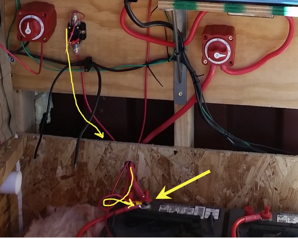
Thank you all for the great ideas and thoughts. Along with tech support at Renogy, most common thought process is that there is a loose connection somewhere, the BATT + on the CC is connected to the same terminal as the inverter, which it should be securely fastened to it's own lug.
As for the gauge of wire, I was using 10 ga on both the BATT +/-, but I might up that to 8 ga. Below is an image of where the CC would be wired to the battery bank....followed by the 4 panels, which are wired in parallel using one cable for pos/neg to the CC.

-
Ok creative assembly you got there. But see what youve done? Youve taken 4 panels which have a 12 guage wire, and combined them into one 12 guage wire. Logically theres going to be 4 times the current in the combined home run, thus needs a bigger wire. Its also (usually) a longer run and a bigger wire will help avoid loss in the cable.This is where the combiner comes in. Those piggybacked mc4 Y's got someone out of bind that day, but for lots of reasons you should use a combiner (with fuses for each string).
When in any doubt about the correct sized wire, hit the voltage drop calculator, (above).
1.8kWp CSUN, 10kWh AGM, Midnite Classic 150, Outback VFX3024E,
http://zoneblue.org/cms/page.php?view=off-grid-solar -
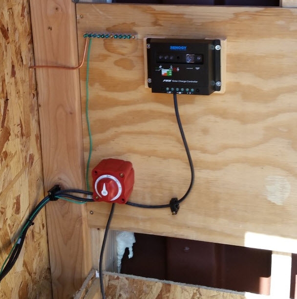
Do you have a ground-wire hooked up to the system and if... how is it wired up? Did your system had over voltage when it was was working?
If you hook up a ground wire to the minus of the solar panel and the minus of the battery, then you have ''shorted/ switched closed'' the controller regulation with your ground wiring. The regulation on most of those kind of controller is on the minus side on the board.
If you have the ground wires hooked up like I said then it will send full power at all times through the controller.
Notice that those panels could put out more than the rating in cooler weather, at least mine did when they where new, add to this a smaller wire and you may ave problems.
-
@zoneblue: You are right, in that sense that the way the wires are run, in hindsight I should have used a combiner box as I am using them in parallel instead of series. As I was so new to this, I tried to do as much research as possible, and based by pv wiring on Renogy's direct documentation for series and parallel wiring. By this winter, I will be adding two more panels and re-wiring that gaggle to have 2 sets of 3 panels in parallel. I would re-do my cable runs, but they are currently buried in the ground and then come up into the shed. Not that easy of a task, but maybe when I add panels later this year.zoneblue said:Ok creative assembly you got there. But see what youve done? Youve taken 4 panels which have a 12 guage wire, and combined them into one 12 guage wire. Logically theres going to be 4 times the current in the combined home run, thus needs a bigger wire. Its also (usually) a longer run and a bigger wire will help avoid loss in the cable.This is where the combiner comes in. Those piggybacked mc4 Y's got someone out of bind that day, but for lots of reasons you should use a combiner (with fuses for each string).
When in any doubt about the correct sized wire, hit the voltage drop calculator, (above).
@Johann: Hi Johann, good question, but yes...I have a ground rod outside the shed and a ground bus that ever component, ends up touching. The charge controller doesn't have a direct touch of the ground bar, because in theory the BATT NEG has a connection to it from the battery bank. It might be possible, when I pick my new CC, that I can add the chassis to the ground bar.
 Johann said:Do you have a ground-wire hooked up to the system and if... how is it wired up? Did your system had over voltage when it was was working?
If you hook up a ground wire to the minus of the solar panel and the minus of the battery, then you have ''shorted/ switched closed'' the controller regulation with your ground wiring. The regulation on most of those kind of controller is on the minus side on the board.
If you have the ground wires hooked up like I said then it will send full power at all times through the controller.
Notice that those panels could put out more than the rating in cooler weather, at least mine did when they where new, add to this a smaller wire and you may ave problems.
-
Yes, with a PWM the current is the same from the "combiner" all the way to the battery. So by increasing the size of the CC to bat wire, you also have to increase the size of the home run. OK, so buried is a pain. What i do when i bury anything, is also lay 4" flexible drain pipe (that i get used for almost nothing), in case i forget something. Which i always do.
Just a suggestion though, that when you do redo things later on, that you think about adding a disconnect to tidy up all the fusing in one place. If you dont want to spend the couple hundred on a MNDC, look at the Big Baby box, and a few MNEPV breakers for it. Will make things much cleaner, and safer.
Also... if you are expanding the array, you might like to ponder moving up to a MPPT controller, such as the Kid. Also something to think about. Good luck, solar is cool eh.
1.8kWp CSUN, 10kWh AGM, Midnite Classic 150, Outback VFX3024E,
http://zoneblue.org/cms/page.php?view=off-grid-solar -
@zoneblue
Thank you for your response. Yes, on the buried cable, I will rethink that in the long run, that part does suck and I should have been smarter. When you live 3 hours away, and only weekends to get things done, you tend to "make due", and in hindsight I might be paying for some of that now. ha.
I am really going to redo a lot of this setup, to include a new 2K pure sine wave inverter, a new MPPT controller (40A to adjust two additional panels), more bus bars to eliminate battery post connections, and more fusing/disconnects in between items. I am really looking forward to this new project. Hadn't planned on spending the additional money on this, but it will be 'new and improved' for sure.
Thanks to everyone on here, and if I get things all sorted out the weekend after this, then I will post photos and summarize the improvements.zoneblue said:Yes, with a PWM the current is the same from the "combiner" all the way to the battery. So by increasing the size of the CC to bat wire, you also have to increase the size of the home run. OK, so buried is a pain. What i do when i bury anything, is also lay 4" flexible drain pipe (that i get used for almost nothing), in case i forget something. Which i always do.
Just a suggestion though, that when you do redo things later on, that you think about adding a disconnect to tidy up all the fusing in one place. If you dont want to spend the couple hundred on a MNDC, look at the Big Baby box, and a few MNEPV breakers for it. Will make things much cleaner, and safer.
Also... if you are expanding the array, you might like to ponder moving up to a MPPT controller, such as the Kid. Also something to think about. Good luck, solar is cool eh.
-
That Renogy 30 amp PWM in the photo is positive "ground". That is unusual and perhaps part of the problem? I have one that I use with a small portable [100 watt] system but it is "floating" with respect to earth and not comparable to your installation.
-
Positive ground = dont bus the negatives anywhere.
1.8kWp CSUN, 10kWh AGM, Midnite Classic 150, Outback VFX3024E,
http://zoneblue.org/cms/page.php?view=off-grid-solar -
timsim00 said:@Johann: Hi Johann, good question, but yes...I have a ground rod outside the shed and a ground bus that ever component, ends up touching. The charge controller doesn't have a direct touch of the ground bar, because in theory the BATT NEG has a connection to it from the battery bank. It might be possible, when I pick my new CC, that I can add the chassis toJohann said:Do you have a ground-wire hooked up to the system and if... how is it wired up? Did your system had over voltage when it was was working?
If you hook up a ground wire to the minus of the solar panel and the minus of the battery, then you have ''shorted/ switched closed'' the controller regulation with your ground wiring. The regulation on most of those kind of controller is on the minus side on the board.
If you have the ground wires hooked up like I said then it will send full power at all times through the controller.
Notice that those panels could put out more than the rating in cooler weather, at least mine did when they where new, add to this a smaller wire and you may ave problems.timsim00 said:@Johann: Hi Johann, good question, but yes...I have a ground rod outside the shed and a ground bus that ever component, ends up touching. The charge controller doesn't have a direct touch of the ground bar, because in theory the BATT NEG has a connection to it from the battery bank. It might be possible, when I pick my new CC, that I can add the chassis to the ground bar.

I am confused/ not sure.Johann said:Do you have a ground-wire hooked up to the system and if... how is it wired up? Did your system had over voltage when it was was working?
If you hook up a ground wire to the minus of the solar panel and the minus of the battery, then you have ''shorted/ switched closed'' the controller regulation with your ground wiring. The regulation on most of those kind of controller is on the minus side on the board.
If you have the ground wires hooked up like I said then it will send full power at all times through the controller.
Notice that those panels could put out more than the rating in cooler weather, at least mine did when they where new, add to this a smaller wire and you may ave problems.
Is the battery minus hooked up to the ground bus bar and is the solar panel minus hooked up to the ground bus bar also ?
Can you post your own excact drawing the way you have everything hooked up, including the ground and the 2 switches and fuses?
-
Hello,
I didn't read everything but I can tell you at a quick glance you should be using an MPPT charge controller. Don't use that cheap one.
Second get rid of that inverter and get a pure sign wave inverter. Appliances do not like modified sign waves. A modified wave is square which is like saying power keeps getting turned off and on at a very fast rate. Electronics hate that. A pure sign wave is much better and healthier for your appliances and electronic items.
Another big tip. Make sure you are using the proper size wiring. Don't try taking a cheap way out with your wiring and components.
-
It tells me the controller has a design flaw.zoneblue said:3 burned out controllers is definitely telling you something! But what...
Perhaps the (-) solder traces on the board are fatter/wider allowing better heat dissipation (more places for negative to go to).
And the (+) is skinny/narrow thus marginal for the specified amperage.
And, once it opens up it becomes a mini-welder due to inverter inductance.
Surely the OP tightened all connections the same and got better skilled with each new controller.
Camden County, NJ, USA
19 SW285 panels
SE5000 inverter
grid tied -
Only thing I'll comment on, is the trench dug next to the concrete pier holding up the building.
Powerfab top of pole PV mount | Listeroid 6/1 w/st5 gen head | XW6048 inverter/chgr | Iota 48V/15A charger | Morningstar 60A MPPT | 48V, 800A NiFe Battery (in series)| 15, Evergreen 205w "12V" PV array on pole | Midnight ePanel | Grundfos 10 SO5-9 with 3 wire Franklin Electric motor (1/2hp 240V 1ph ) on a timer for 3 hr noontime run - Runs off PV ||
|| Midnight Classic 200 | 10, Evergreen 200w in a 160VOC array ||
|| VEC1093 12V Charger | Maha C401 aa/aaa Charger | SureSine | Sunsaver MPPT 15A
solar: http://tinyurl.com/LMR-Solar
gen: http://tinyurl.com/LMR-Lister ,
Categories
- All Categories
- 234 Forum & Website
- 142 Solar Forum News and Announcements
- 1.4K Solar News, Reviews, & Product Announcements
- 200 Solar Information links & sources, event announcements
- 901 Solar Product Reviews & Opinions
- 256 Solar Skeptics, Hype, & Scams Corner
- 22.5K Solar Electric Power, Wind Power & Balance of System
- 3.5K General Solar Power Topics
- 6.7K Solar Beginners Corner
- 1K PV Installers Forum - NEC, Wiring, Installation
- 2.1K Advanced Solar Electric Technical Forum
- 5.6K Off Grid Solar & Battery Systems
- 430 Caravan, Recreational Vehicle, and Marine Power Systems
- 1.1K Grid Tie and Grid Interactive Systems
- 656 Solar Water Pumping
- 817 Wind Power Generation
- 624 Energy Use & Conservation
- 624 Discussion Forums/Café
- 316 In the Weeds--Member's Choice
- 75 Construction
- 125 New Battery Technologies
- 108 Old Battery Tech Discussions
- 3.8K Solar News - Automatic Feed
- 3.8K Solar Energy News RSS Feed

