Please help me figure out this electrical box...
Comments
-
Re: Please help me figure out this electrical box...The 3 links in my .sig below, have many photos
Thank for the pics mike...
I see you have the morningstar fanless inverter...which relates to my set up..
What all are you running off it on average?
And how would you rate its performance?
--kaxe~1.5Kw PV in parallel
Morningstar MPPT-60 controllers (2) in parallel
3 Trojan tr-1275's in parallel 450ah total
Samlex 2,000 watt 12-volt inverter hardwired -
Re: Please help me figure out this electrical box...
If this was a real AC mains box, you would probably have a 6 awg minimum copper wire to the ground rod.
In this case, you have a relatively small AC inverter--So the grounding for the AC box only has to be large enough to manage a short ciruit current from the 1,500 Watt inverter (~13 amps or so). So a 14-12 AWG ground wire is sufficient.
The short to the Inverter Case is from your DC feed--So that ground wire has to be enough to "shunt/short" the DC power from battery bank (through the fuse and DC wiring).
To the ground rod itself, there is really not low enough resistance to the AC ground rod that you can get that much current through it. I think the worst case resistance to earth is ~25 Ohms:
120 VAC / 25 Ohms = 4.8 amps if you somehow got 120 VAC between the Ground rod and a cold water pipe.
We default to NEC code requirement of 6 AWG minimum... That seems to be a good minimum size for lightning strike (wire does not vaporize) and also mechanically strong enough for the wire to not fail (exposed to outside people/dogs/etc.) and also the minimum awg for direct burial.
Very roughly the fusing current for 6 AWG cable is on the order of 600 amps.
-BillNear San Francisco California: 3.5kWatt Grid Tied Solar power system+small backup genset -
Re: Please help me figure out this electrical box...Thank for the pics mike...
I see you have the morningstar fanless inverter...which relates to my set up..
What all are you running off it on average?
And how would you rate its performance?
--kaxe
The MS 300w/600surge inverter, a 200W panel, with the sunsaver MPPT, was the first array and battery charging station till the shop
and main array went in. Currently, the inverter has been running 24/7 for 3 years now, powering a string of cool white LED lights at the privy. I've not tried to run a fridge with it. But it's been a great inverter, and I have plans to use another one at a different site here.Powerfab top of pole PV mount | Listeroid 6/1 w/st5 gen head | XW6048 inverter/chgr | Iota 48V/15A charger | Morningstar 60A MPPT | 48V, 800A NiFe Battery (in series)| 15, Evergreen 205w "12V" PV array on pole | Midnight ePanel | Grundfos 10 SO5-9 with 3 wire Franklin Electric motor (1/2hp 240V 1ph ) on a timer for 3 hr noontime run - Runs off PV ||
|| Midnight Classic 200 | 10, Evergreen 200w in a 160VOC array ||
|| VEC1093 12V Charger | Maha C401 aa/aaa Charger | SureSine | Sunsaver MPPT 15A
solar: http://tinyurl.com/LMR-Solar
gen: http://tinyurl.com/LMR-Lister , -
Re: Please help me figure out this electrical box...
OK guys, I changed my mind about the samlex 1500 inverter (for now)
Instead I'm going to go with the Morningstar 'suresine' 300watt inverter that many here have experience with...
Anyway form reading the online owners manual from Morningstar it appears that this inverter is NOT neutral/ground bonded internaly --
So this means I have to do it in my BOX correct?
So thats my question....
Below is a photo of my actual set up so far -- as you can see I added a dedicated ground bar on the BOTTOM of the box where all the greens go - Now, all I have to do to get this to work with the Morningstar inverter is to add the GREEN 'bonding' screw in the 'bridge' of the neutral bar in the box right?
the screw goes through the bar into the metal casing of the box, thus 'bonding' to the ground bar also attached to the box at the bottom...do I have all this right?
Thanks everyone for your help-
--cupz
Attachment not found.~1.5Kw PV in parallel
Morningstar MPPT-60 controllers (2) in parallel
3 Trojan tr-1275's in parallel 450ah total
Samlex 2,000 watt 12-volt inverter hardwired -
Re: Please help me figure out this electrical box...
Bump.....,..........~1.5Kw PV in parallel
Morningstar MPPT-60 controllers (2) in parallel
3 Trojan tr-1275's in parallel 450ah total
Samlex 2,000 watt 12-volt inverter hardwired -
Re: Please help me figure out this electrical box...
Yes, and you need to add a green ground wire from the bottom ground bus to the ground rod/common system ground point (single point ground). Typically a 6 awg wire from ground bus to ground master ground rod.
A second 6 awg from battery negative ground common/bus to master ground rod (same rod as AC ground). This "negative ground common/bus" point is now both your DC Return common and DC safety ground green wire common connection point (basically just like you made your AC panel the common Return+Green wire ground point for all your AC power). Make sure you do not "touch"/"bond" AC and DC grounds together any place else in your system (this means your AC box and the next door charge controller sheet metal do not touch, and you should not connect Inverter Chassis to AC Panel with metal conduit)--This prevents multi-point ground connections.
If you install a additional ground rods, connect your 6 awg (minimum) cable from your "Master Ground Rod" to any additional rods (do not connect AC ground to one rod and DC ground to a second rod).
-BillNear San Francisco California: 3.5kWatt Grid Tied Solar power system+small backup genset -
Re: Please help me figure out this electrical box...Yes, and you need to add a green ground wire from the bottom ground bus to the ground rod/common system ground point (single point ground). Typically a 6 awg wire from ground bus to ground master ground rod.
A second 6 awg from battery negative ground common/bus to master ground rod (same rod as AC ground). This "negative ground common/bus" point is now both your DC Return common and DC safety ground green wire common connection point (basically just like you made your AC panel the common Return+Green wire ground point for all your AC power). Make sure you do not "touch"/"bond" AC and DC grounds together any place else in your system (this means your AC box and the next door charge controller sheet metal do not touch, and you should not connect Inverter Chassis to AC Panel with metal conduit)--This prevents multi-point ground connections.
If you install a additional ground rods, connect your 6 awg (minimum) cable from your "Master Ground Rod" to any additional rods (do not connect AC ground to one rod and DC ground to a second rod).
-Bill
Ok so ac and dc can ALL connect to the SAME master ground ???
So my rod is touching:
AC box bonded with neutral
DC chassises (controller, inverter)
DC battery negative terminal
Is this correct??~1.5Kw PV in parallel
Morningstar MPPT-60 controllers (2) in parallel
3 Trojan tr-1275's in parallel 450ah total
Samlex 2,000 watt 12-volt inverter hardwired -
Re: Please help me figure out this electrical box...So my rod is touching:
DC chassises (controller, inverter)
DC battery negative terminal
This part... This can be done by running a heavy ground cable (size of your DC inverter wiring) from Chassis ground to ground rod. And from DC battery - bus common to ground rod.
Or, you run heavy wire from DC Inverter Chassis to Battery Bus common ground; And a smaller (6 awg minimum) from DC battery - bus common to ground rod.
It does not matter too much where you make your single point of ground bonding--It can all be at the Master Ground Rod--Or you can create "local" common grounds (like the AC Neutral+Green Wire ground in your AC panel, and a second DC common ground at your battery negative Bus connection. And from each of those "common local grounds" run a single green wire (6 awg minimum) from the common "local ground" to the master ground rod.
The issue with mixing AC vs DC grounds is that the DC side may have 10x the current vs the AC side (example of 120 VAC vs 12 VDC inverter--10x more current on the DC side for the same power--Power=Voltage*Current)--So you have to be very careful that DC Fault Current does not somehow flow through AC grounding cable(s).
I.e., a 14 gauge wire can will have a 15 amp breaker per NEC. But the cable on the DC side of the inverter would need to be rated ~150 amps (actually, with losses and "worst case engineering" >~168 amps for a 1,200 watt AC 12 volt input inverter). You do not want a 175 Amp DC circuit to find a short circuit through your 14 AWG green wire AC grounding.
That is why you either need to keep your AC common ground "separate" from your DC common grounds. Or you need to cable (at least some) of your AC/Common grounding with much heavier cable. If you mix/match grounds, you could be forced to replace all your 14 AWG ground wires with 175 amp rated (2/O to 4/O) ground wire (again assuming a 1,200 watt 12 VDC input inverter)...
If you keep your DC side wiring separate from your AC side wiring--Then the AC side is "sized" for your 120 VAC AC currents and your DC side is sized for your ~10x larger currents.
Those two "local AC and DC grounds" are then connected to the Master Ground Rod with 6 AWG cable. Since no DC faults can flow through a separate AC power system, there is no DC Fault Current flowing through the 6 AWG cable at the ground rod (6 AWG is plenty heavy enough for most AC systems up to full grid connected AC mains).
If, for example, you connect your AC inverter Chassis Ground (which can short to the DC main input power) to the Master Ground Rod, then you need a similar sized cable from the master ground rod to the DC coming negative bus (to manage short circuit current). This may, worst case, mean you need a few feet more of the more expensive larger gauge cable.
Your first inverter was a 12 volt @ 1,500 watts--A pretty good sized inverter. I think now you are looking at a MorningStar 300 watt (600 watt for 10 minutes) which, if I recall correctly is a 6 AWG cable per their manual. So a 6 AWG DC Safety ground cable and the standard 6 AWG ground cable are the same with this smaller inverter.
300 watts * 1/0.85 inverter eff * 1/10.5 inverter battery cutoff * 1.25 NEC derating = 42 Amp branch circuit. 6 AWG is fine.
Now, if you plan on running the inverter closer to 600 watts for ~10 minutes, you might want to look at 4 AWG just to keep voltage drop lower and cabling cooler.
Sorry for the long explanation--Grounding is not simple subject. And proper grounding can be done using different methods--But each has its own "gotchas" you need to avoid.
My short answer/suggestion (after all of the above :roll:)--Create an AC main ground in your main AC panel-Connect with 6 AWG to master ground rod.
Make your DC negative battery bus your "common/local" DC ground. Run all DC safety grounds (and negative return cables) to this common/local DC ground. Then connect a 6 AWG cable from common/local DC ground to the Master Ground rod.
Any other "ground wires" (antenna grounds (that enter the home), metal water and propane plumbing, etc.) all have their single point ground connected to the master ground rod too (again, usually 6 AWG, although I have seen the phone companies use smaller gauge cable--That rule for "other grounds" would be the green wire to the ground rod should be at least as large as the cabling system you are grounding with 6 AWG being the maximum required).
When you ground your PV array (panel frames) and metal frame work). Run the 6 awg ground wire directly to the master ground rod (if pretty much a straight run down the roof and on the outside of the building to your master ground rod.
If the array is more than ~10 feet away (sideways) from the master ground rod, drive another ground rod local to the array. And (ideally) run another 6 awg ground cable from the remote ground rod to your main ground rod (ground rods are for lightning protection, 6 awg connection between local and remote ground is for electrical grounding in the case of short circuits, people nearby to avoid shocks).
Have I lost you yet--Or gone completely crazy myself and none of this makes any sense?
-BillNear San Francisco California: 3.5kWatt Grid Tied Solar power system+small backup genset -
Re: Please help me figure out this electrical box...This part... This can be done by running a heavy ground cable (size of your DC inverter wiring) from Chassis ground to ground rod. And from DC battery - bus common to ground rod.
Or, you run heavy wire from DC Inverter Chassis to Battery Bus common ground; And a smaller (6 awg minimum) from DC battery - bus common to ground rod.
It does not matter too much where you make your single point of ground bonding--It can all be at the Master Ground Rod--Or you can create "local" common grounds (like the AC Neutral+Green Wire ground in your AC panel, and a second DC common ground at your battery negative Bus connection. And from each of those "common local grounds" run a single green wire (6 awg minimum) from the common "local ground" to the master ground rod.
The issue with mixing AC vs DC grounds is that the DC side may have 10x the current vs the AC side (example of 120 VAC vs 12 VDC inverter--10x more current on the DC side for the same power--Power=Voltage*Current)--So you have to be very careful that DC Fault Current does not somehow flow through AC grounding cable(s).
I.e., a 14 gauge wire can will have a 15 amp breaker per NEC. But the cable on the DC side of the inverter would need to be rated ~150 amps (actually, with losses and "worst case engineering" >~168 amps for a 1,200 watt AC 12 volt input inverter). You do not want a 175 Amp DC circuit to find a short circuit through your 14 AWG green wire AC grounding.
That is why you either need to keep your AC common ground "separate" from your DC common grounds. Or you need to cable (at least some) of your AC/Common grounding with much heavier cable. If you mix/match grounds, you could be forced to replace all your 14 AWG ground wires with 175 amp rated (2/O to 4/O) ground wire (again assuming a 1,200 watt 12 VDC input inverter)...
If you keep your DC side wiring separate from your AC side wiring--Then the AC side is "sized" for your 120 VAC AC currents and your DC side is sized for your ~10x larger currents.
Those two "local AC and DC grounds" are then connected to the Master Ground Rod with 6 AWG cable. Since no DC faults can flow through a separate AC power system, there is no DC Fault Current flowing through the 6 AWG cable at the ground rod (6 AWG is plenty heavy enough for most AC systems up to full grid connected AC mains).
If, for example, you connect your AC inverter Chassis Ground (which can short to the DC main input power) to the Master Ground Rod, then you need a similar sized cable from the master ground rod to the DC coming negative bus (to manage short circuit current). This may, worst case, mean you need a few feet more of the more expensive larger gauge cable.
Your first inverter was a 12 volt @ 1,500 watts--A pretty good sized inverter. I think now you are looking at a MorningStar 300 watt (600 watt for 10 minutes) which, if I recall correctly is a 6 AWG cable per their manual. So a 6 AWG DC Safety ground cable and the standard 6 AWG ground cable are the same with this smaller inverter.
300 watts * 1/0.85 inverter eff * 1/10.5 inverter battery cutoff * 1.25 NEC derating = 42 Amp branch circuit. 6 AWG is fine.
Now, if you plan on running the inverter closer to 600 watts for ~10 minutes, you might want to look at 4 AWG just to keep voltage drop lower and cabling cooler.
Sorry for the long explanation--Grounding is not simple subject. And proper grounding can be done using different methods--But each has its own "gotchas" you need to avoid.
My short answer/suggestion (after all of the above :roll:)--Create an AC main ground in your main AC panel-Connect with 6 AWG to master ground rod.
Make your DC negative battery bus your "common/local" DC ground. Run all DC safety grounds (and negative return cables) to this common/local DC ground. Then connect a 6 AWG cable from common/local DC ground to the Master Ground rod.
Any other "ground wires" (antenna grounds (that enter the home), metal water and propane plumbing, etc.) all have their single point ground connected to the master ground rod too (again, usually 6 AWG, although I have seen the phone companies use smaller gauge cable--That rule for "other grounds" would be the green wire to the ground rod should be at least as large as the cabling system you are grounding with 6 AWG being the maximum required).
When you ground your PV array (panel frames) and metal frame work). Run the 6 awg ground wire directly to the master ground rod (if pretty much a straight run down the roof and on the outside of the building to your master ground rod.
If the array is more than ~10 feet away (sideways) from the master ground rod, drive another ground rod local to the array. And (ideally) run another 6 awg ground cable from the remote ground rod to your main ground rod (ground rods are for lightning protection, 6 awg connection between local and remote ground is for electrical grounding in the case of short circuits, people nearby to avoid shocks).
Have I lost you yet--Or gone completely crazy myself and none of this makes any sense?
-Bill
Mr. Bill -
Don't be sorry at all for rambling - I am practically following your suggestions word for word here! I MUCH appreciate your help AND your lengthy explanations for an eager, yet conscientious n00b such as myself. I am literally out in the desert heat right now in my speedos banging in the 8 foot grounding rods for the system...
Anyway - according to your instructions in your last post I made the attached diagram (see photo below)...
DO I FINALLY HAVE THIS CORRECT?
Thank you again Mr. Bill and others...
--C.Cakes~1.5Kw PV in parallel
Morningstar MPPT-60 controllers (2) in parallel
3 Trojan tr-1275's in parallel 450ah total
Samlex 2,000 watt 12-volt inverter hardwired -
Re: Please help me figure out this electrical box...
Looks perfect.
-BillNear San Francisco California: 3.5kWatt Grid Tied Solar power system+small backup genset -
Re: Please help me figure out this electrical box...Looks perfect.
-Bill
Sweet cupcakes I'm so glad...
Another question:
Does the #4 FROM the battery bus TO the grounding rod need to be "continuous" ...running from.the first rod acorn.to the second rod acorn??
Or can it just connect to the first acorn only???
Thanxxxx
--c~1.5Kw PV in parallel
Morningstar MPPT-60 controllers (2) in parallel
3 Trojan tr-1275's in parallel 450ah total
Samlex 2,000 watt 12-volt inverter hardwired -
Re: Please help me figure out this electrical box...
No--The "continuous" ground cable is from the Green Wire/Chassis bond to the first ground rod (as far as I know).
In "professional" installations (and checked by building inspectors), they do not want "bolt connections" that can be disconnected by somebody/somewhere and now the "safety ground" is compromised.
Even for "simple" green wire to chassis connections, the ground connection needs to be either dedicated, or if you have a threaded stud--You put the ground connection down first and then a washer and nut--Then stack the rest of the "non-Safety" ground connections on top.
Even the ground connections from each solar panel frame to the first earth ground needs to be continuous (per code) (or approved welding/crimp connections) from panel frame to earth.
-BillNear San Francisco California: 3.5kWatt Grid Tied Solar power system+small backup genset -
Re: Please help me figure out this electrical box...
Update:
I am up and running.
I'd like to thank everyone here who helped me... especially."BB"...
One final question...
Is the suresine300 supposed to make an audible clicking in standby mode each time the green LED blinks??
Reminds me if grandmas old pendulum clock?
Normal?
Thanxxx~1.5Kw PV in parallel
Morningstar MPPT-60 controllers (2) in parallel
3 Trojan tr-1275's in parallel 450ah total
Samlex 2,000 watt 12-volt inverter hardwired -
Re: Please help me figure out this electrical box...
It is turning on for 1/2 or 1 cycle (of 60 cycles per second) looking for a load--So I could understand hearing a small tick every time it does it.
But I don't own one, so I cannot deny or confirm... I am sure somebody else can.
How about some pictures and a small write up on your system and how it is working for you (after a few weeks) and any suggestions you may have for the next person.
You are very welcome.
-Bill Near San Francisco California: 3.5kWatt Grid Tied Solar power system+small backup genset
 -
Re: Please help me figure out this electrical box...
This thread scares the he** out of me.
The OP has a basic lack of electrical theory. Does not know the basic grounding, bonding and electrical safety procedures. He is making electrical connections without knowing the basic OCD and wiring load calculations.
This is an accident or worse waiting to happen. My advice to the OP is to hire a qualified and licensed electrician to inspect his system. It could save his property or even his life.23.16kW Kyocera panels; 2 Fronius 7.5kW inverters; Nyle hot water; Steffes ETS; Great Lakes RO; Generac 10kW w/ATS, TED Pro & Emporia System monitoring since 2011 -
Re: Please help me figure out this electrical box...This thread scares the he** out of me.
The OP has a basic lack of electrical theory. Does not know the basic grounding, bonding and electrical safety procedures. He is making electrical connections without knowing the basic OCD and wiring load calculations.
This is an accident or worse waiting to happen. My advice to the OP is to hire a qualified and licensed electrician to inspect his system. It could save his property or even his life.
Dan... seriously??
This forum is meant to HELP people.
I am a contractor by trade for decades... I'm not an electrician..
I asked on here for answers to my questions...or as you say 'my lack of basic understanding'...
BB and others gave me the answers...
The system is up..working..properly grounded and safe...
People aren't born knowing everything... that's why people ask questions...
BB took me to school and now I UNDERSTAND how everything works...
Thanks again to all that helped...I'm a n00b but not stupid or born yesterday ...point me in the right direction and I'll 'get it' soon enough...~1.5Kw PV in parallel
Morningstar MPPT-60 controllers (2) in parallel
3 Trojan tr-1275's in parallel 450ah total
Samlex 2,000 watt 12-volt inverter hardwired -
Re: Please help me figure out this electrical box...It is turning on for 1/2 or 1 cycle (of 60 cycles per second) looking for a load--So I could understand hearing a small tick every time it does it.
But I don't own one, so I cannot deny or confirm... I am sure somebody else can.
How about some pictures and a small write up on your system and how it is working for you (after a few weeks) and any suggestions you may have for the next person.
You are very welcome.
-Bill
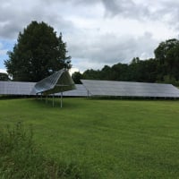
Heres some pics of the rods in the ground... as well as the system itself....
Thanks again Mr. Bill (BB)
Attachment not found.Attachment not found.Attachment not found.~1.5Kw PV in parallel
Morningstar MPPT-60 controllers (2) in parallel
3 Trojan tr-1275's in parallel 450ah total
Samlex 2,000 watt 12-volt inverter hardwired -
Re: Please help me figure out this electrical box...This thread scares the he** out of me.
...
This is an accident or worse waiting to happen. My advice to the OP is to hire a qualified and licensed electrician to inspect his system. It could save his property or even his life.
Its never bad advice to get an electrician to sign off your DIY job. If you ask around you can usually find a qualified solar friendly contractor who is happy to bill you a couple hours plus travel to look over your install. Money well spent if it means you sleep better at night knowing you and your loved ones are safe.1.8kWp CSUN, 10kWh AGM, Midnite Classic 150, Outback VFX3024E,
http://zoneblue.org/cms/page.php?view=off-grid-solar -
Re: Please help me figure out this electrical box...
Be very careful with advise from a general contractor licensed electrician... Many have areas of specialization (home, industrial, etc.).
Many do not have much experience with DC and high power DC systems (i.e., high current DC). A couple did not make the connection that 10 amps at 120 VAC is something like 120 Amps at 12 VDC (14 AWG wire can carry 1,200 watts just fine--Yes, at 120 VAC).
If they are willing to teach/explain, and you are willing to learn/ask questions--It can be very educational for you, and sometimes for the electrician. If they cannot/will not give a simple explanation of what/why the recommend something--Be careful.
I have a friend that is a machinist--And he has seen many electricians that have no idea how to wire up a 5 HP 1 or 3 phase motor with a contactor--Not even close to having a clue.
-BillNear San Francisco California: 3.5kWatt Grid Tied Solar power system+small backup genset

Categories
- All Categories
- 230 Forum & Website
- 137 Solar Forum News and Announcements
- 1.3K Solar News, Reviews, & Product Announcements
- 180 Solar Information links & sources, event announcements
- 892 Solar Product Reviews & Opinions
- 252 Solar Skeptics, Hype, & Scams Corner
- 22.5K Solar Electric Power, Wind Power & Balance of System
- 3.5K General Solar Power Topics
- 6.7K Solar Beginners Corner
- 1K PV Installers Forum - NEC, Wiring, Installation
- 2.1K Advanced Solar Electric Technical Forum
- 5.6K Off Grid Solar & Battery Systems
- 428 Caravan, Recreational Vehicle, and Marine Power Systems
- 1.1K Grid Tie and Grid Interactive Systems
- 656 Solar Water Pumping
- 816 Wind Power Generation
- 620 Energy Use & Conservation
- 622 Discussion Forums/Café
- 316 In the Weeds--Member's Choice
- 74 Construction
- 125 New Battery Technologies
- 107 Old Battery Tech Discussions
- 3.8K Solar News - Automatic Feed
- 3.8K Solar Energy News RSS Feed