Help with my project
Art
Solar Expert Posts: 32 ✭
Hi Guys,
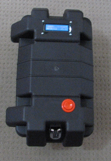
I'm putting together a portable camping system consisting of a single SLA battery,
a single solar panel, charge controller, inverter, and a custom made microcontroller
driven battery monitor with a 2 line x 16 character LCD screen.
Some details (with video) of the custom microcontroller part of the project are here:
http://www.freewebs.com/defxev/Sun.htm
So I don't have to explain that part again on a forum.
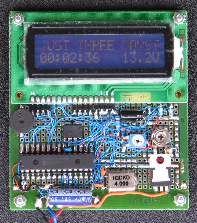
Sexy isn't it")
Now I also want my microcontroller circuit to know when the solar panel is charging the battery.
Rather than go to the trouble of including an ammeter in the circuit and programming,
I thought I'd use the LED of the solar charge controller as input for my circuit
(ie. just connect the pin for the charging indicator LED to an input pin of my micro).
I noticed (re: my solar charge controller) that the ground terminal for the battery
and the ground terminal for the load are common.
There is almost zero resistance between them while the charge controller is
powered on.
Since my circuit is powered from the load terminals of the charge controller,
it seems that only one connection to the charging indicator LED pin would be required.
My question is would this be safe for the controller?
Would it introduce any new loop that is not supposed to happen between the
battery and load terminals of the charge controller because they are now somehow
connected via my microcontroller circuit?
Or doesn't this matter, and why?
Cheers, Art.
I'm putting together a portable camping system consisting of a single SLA battery,
a single solar panel, charge controller, inverter, and a custom made microcontroller
driven battery monitor with a 2 line x 16 character LCD screen.
Some details (with video) of the custom microcontroller part of the project are here:
http://www.freewebs.com/defxev/Sun.htm
So I don't have to explain that part again on a forum.
Sexy isn't it
Now I also want my microcontroller circuit to know when the solar panel is charging the battery.
Rather than go to the trouble of including an ammeter in the circuit and programming,
I thought I'd use the LED of the solar charge controller as input for my circuit
(ie. just connect the pin for the charging indicator LED to an input pin of my micro).
I noticed (re: my solar charge controller) that the ground terminal for the battery
and the ground terminal for the load are common.
There is almost zero resistance between them while the charge controller is
powered on.
Since my circuit is powered from the load terminals of the charge controller,
it seems that only one connection to the charging indicator LED pin would be required.
My question is would this be safe for the controller?
Would it introduce any new loop that is not supposed to happen between the
battery and load terminals of the charge controller because they are now somehow
connected via my microcontroller circuit?
Or doesn't this matter, and why?
Cheers, Art.
Comments
-
Re: Help with my project
A schematic would be a help.
Your microcontroller should be able to read a logic level somewhere. Perhaps you will need an I/O and latch.
If your LED voltage is sufficient to trigger your logic state, then it should be adequate for a signal. You don't spec your parts, and I am too old to try to read fuzzy brands.
As regards common grounds, that would be a default to star them all together.
If you have power noise on your logic ground, well then you will have some fun. -
Re: Help with my project
It's a Microchip Pic 16F876.
I'm using an ADC pin to read the voltage from the same line as the power supply
before it is regulated for the microcontroller.
A resistor voltage divider corrects the range before the ADC input pin sees it.
So right now, the circuit connects very neatly via only the two wires that power the circuit.
I did a schematic of that part for another forum:
Yes, I know the micro can read a logic level from the solar charge controller's LED pin.
I have no doubt that would work, it's just whether or or not it's good for the controller
(ie. when the controller shuts off the load, maybe there is leakage through the micro or something like that).
It's just that I have limited knowledge of how the solar charge controller works.
The two grounds are only connected together when the controller is powered on BTW.
It has it's own soft power on/off button switch. -
Re: Help with my project
Just use a 20K resistor in series from the PIC IO pin and your logic sense, this will protect the pin -
Re: Help with my projectSolar Guppy wrote: »Just use a 20K resistor in series from the PIC IO pin and your logic sense, this will protect the pin
I'm not worried about protecting the microcontroller in my circuit.
Any supply the solar charge controller uses to power the indicator LED will not harm my circuit,
and the pin it is connected to will always be an input.
and even if it blew up, there's plenty more where that one came from:
It's the charge controller I'm worried about.
I would typically connect the LED pin on the controller directly to the pic IO pin,
and tie it to ground with a 10K resistor to pull down to ground when the pin is not live. -
Re: Help with my project
The off state leakage of your controller should not be affected by a logic load or a 10k Resistor load.
And if a microcontroller with a 1k series ESD resistor wins a battle with the controller for EOS then you have a lousy controller. -
Re: Help with my project
Fair enough, I'll see how I go then, thanks guys.
The program of mine could be a lot smarter with this information.
Keeping track of charging time, relative battery condition, etc. could all be calculated
as I'm sure there are systems already out there that do this and more.


Categories
- All Categories
- 233 Forum & Website
- 140 Solar Forum News and Announcements
- 1.3K Solar News, Reviews, & Product Announcements
- 181 Solar Information links & sources, event announcements
- 895 Solar Product Reviews & Opinions
- 252 Solar Skeptics, Hype, & Scams Corner
- 22.5K Solar Electric Power, Wind Power & Balance of System
- 3.5K General Solar Power Topics
- 6.7K Solar Beginners Corner
- 1K PV Installers Forum - NEC, Wiring, Installation
- 2.1K Advanced Solar Electric Technical Forum
- 5.6K Off Grid Solar & Battery Systems
- 428 Caravan, Recreational Vehicle, and Marine Power Systems
- 1.1K Grid Tie and Grid Interactive Systems
- 656 Solar Water Pumping
- 816 Wind Power Generation
- 621 Energy Use & Conservation
- 623 Discussion Forums/Café
- 316 In the Weeds--Member's Choice
- 74 Construction
- 125 New Battery Technologies
- 108 Old Battery Tech Discussions
- 3.8K Solar News - Automatic Feed
- 3.8K Solar Energy News RSS Feed