Wiring Diagram

maddyhughes27
Registered Users Posts: 4 ✭
Would love to hear any input on my wiring diagram! My main questions right now:
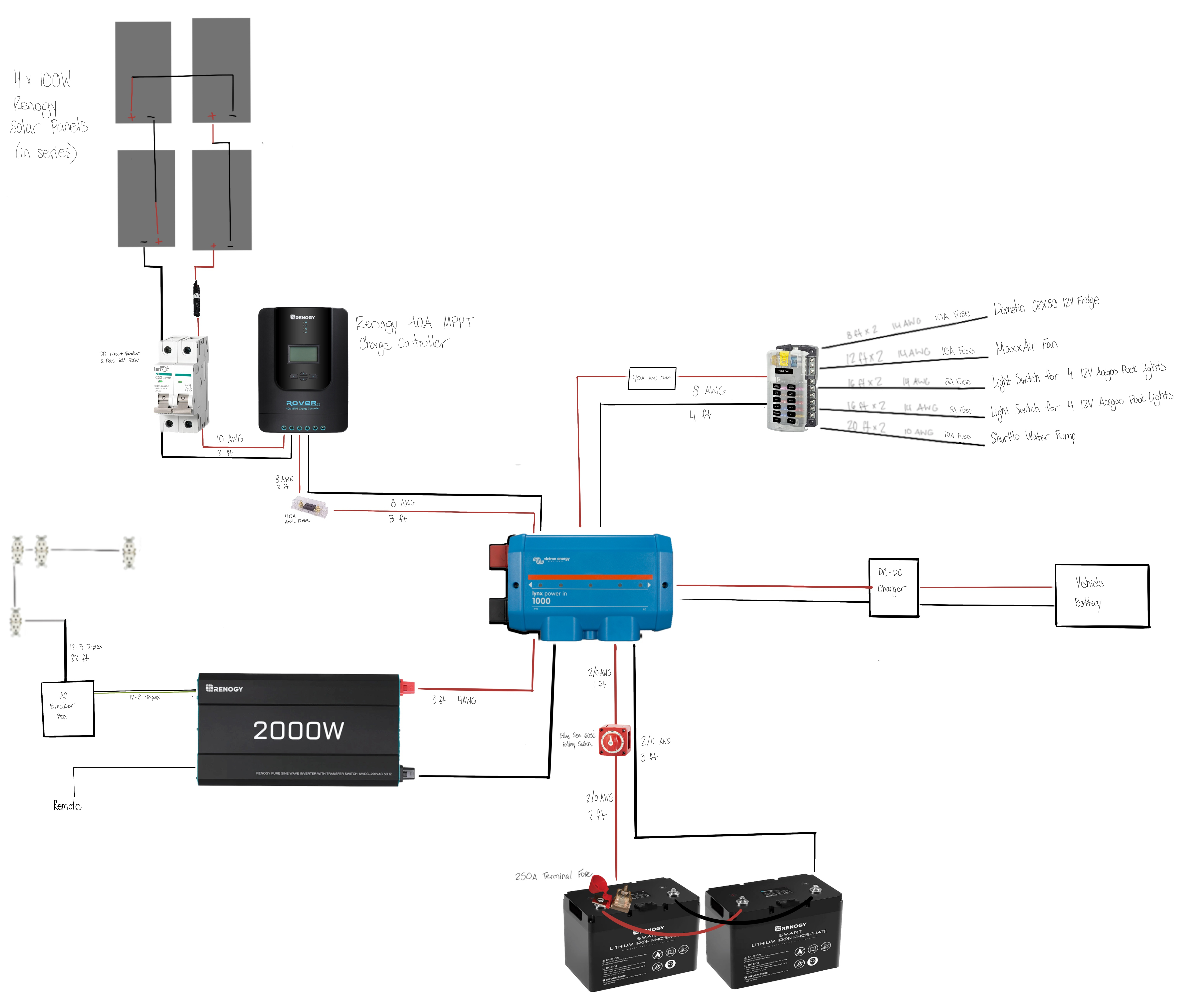
1. How do you determine wire gauge for grounding the system? Also, should I ground from the inverter and the negative bus bar, or is just the negative bus bar enough since the inverter will already be connected to it?
2. Any suggestions on AC breaker boxes to use?
3. Any suggestions for DC-DC chargers for a 2015 Ford Transit 250? I initially wasn’t going to have alternator charging but decided it might be a good idea so I’m just startging to look into how to add that in here.
4. Do I need switches or fuses anywhere else?
Comments
-
A quick set of comments (late at night here):
Generally, 6 AWG is a good choice for minimum grounding cable size for up to a 150 Amp service (National electric code). For a 250 Amp service, then 2 AWG is technically required:
https://learnmetrics.com/ground-wire-size-chart-nec-grounding-conductor-size-chart/
Generally, you only want single point grounding for power wiring. If you do multi-point grounding (say negative bus bar, and negative terminal to AC inverter), then you have current flow split between the negative power cable, and the "system grounding"... You normally design a system so that there is no current flow through the ground system, except if there is a short circuit.
There are times to do multi-point grounding--But that is usually for larger home/commercial installations and using multiple earth ground rods. Does not apply here.
Don't forget to ground electrical devices with metal chassis. For example, on your 2 kWatt you should see a chassis grounding screw or stud to attach the (green) ground wire too... Use this especially if the inverter is mounted to, for example, a wood panel for proper safety grounding.
For AC Breaker boxes (and circuit breakers), you can just go by your local hardware store and pickup a smaller box (typically, for 120 VAC power in the USA, 15 amps @ 14 AWG cable is the minimum circuit rating. You could with the "smallish" 2 kWatt inverter use 2-4 circuits... One to a large heavy load (such as an induction cook top and an electric water heater... Plus another to your AC outlets, lightning, etc.
I don't have any specific DC to DC charge controllers--Victron makes one (at least). An alternative is to mount a second alternator for the house battery bank. With lithium batteries, they can take 100-200+ amps for charging (depending on the exact batteries you have).
Regarding switches/breaker/fuses...
For the solar array--Do you have both a fuse in the "red wire" and a double pole circuit breaker? You generally avoid using both fuses and breakers in "series". It is duplicative and makes debugging a bit of a pain (did the breaker pop, or did the fuse).
Also, when you have a negative ground battery bank, you really only need fuses/breaker in the positive cable. The double pole breaker is "over kill". And in this case, you really do not need a fuse/circuit breaker in this array configuration. The solar panels will not "overheat" a shorted 10 AWG cable.
Your 400 Watt array is probably around Vmp-array~72 VDC Vmp and 5.56 Amps Imp and 7 amps Isc. 10 AWG is good for 30 amps (NEC):
https://lugsdirect.com/WireCurrentAmpacitiesNEC-Table-301-16.htm
In solar power systems... Many times use circuit breakers instead of fuses or fuses+switches (to turn off power, reset controllers, servicing).
And regarding DC power systems--Make sure your breakers, switches, and fuses are rated for XXX volts @ YY Amps DC. Direct Current is much more difficult to "break" (switch) vs AC. An AC rated breaker can arc internally and even catch fire when switching DC current. https://www.youtube.com/watch?v=Zez2r1RPpWY
Not a fan of "Marine DC Switches". You could replace the rotary switch + Blue Sky DC fuse (this is a nice fuse assembly with a single 250 Amp circuit breaker for both over current protection and an on/off switch.
I could not see the ratings/model of the lithium batteries. This are "smart batteries" with a built in BMS (Battery management system). Make sure they are rated for your planned DC loading (and charging) currents.
Check your DC power cabling from the battery. Using 250 Amp breakers with 2/0 cable but only 4 AWG to the AC inverter (good for around 95 amps max from NEC chart above). If connected to 250 amp bus, and no addition breaker protection to 4 AWG cable.
Also, a 2,000- Watt inverter draws:- 2,000 Watts * 1/0.85 AC inverter eff * 1/10.5 volts battery cutoff voltage = 224 Amps max continuous draw.
If you plan on using > 1,000 Watts, you probably need heavier than 4 AWG cable.
As always, review the installation manual to ensure you have things wired correctly (using NEC numbers are a bit on conservative side...).
Also there is the issue of voltage drop. You have to calculate voltage drop vs AWG size vs cable length. On long 12 VDC wire runs, frequently need larger AWG cables to keep voltage drop reasonable (can do another post if you need more information).
-BillNear San Francisco California: 3.5kWatt Grid Tied Solar power system+small backup genset -
Thank you Bill! Appreciate your thorough feedback.BB. said:A quick set of comments (late at night here):
Generally, 6 AWG is a good choice for minimum grounding cable size for up to a 150 Amp service (National electric code). For a 250 Amp service, then 2 AWG is technically required:
https://learnmetrics.com/ground-wire-size-chart-nec-grounding-conductor-size-chart/
Generally, you only want single point grounding for power wiring. If you do multi-point grounding (say negative bus bar, and negative terminal to AC inverter), then you have current flow split between the negative power cable, and the "system grounding"... You normally design a system so that there is no current flow through the ground system, except if there is a short circuit.
There are times to do multi-point grounding--But that is usually for larger home/commercial installations and using multiple earth ground rods. Does not apply here.
Don't forget to ground electrical devices with metal chassis. For example, on your 2 kWatt you should see a chassis grounding screw or stud to attach the (green) ground wire too... Use this especially if the inverter is mounted to, for example, a wood panel for proper safety groundingI’m still a bit unclear on grounding. You mention wanting single point grounding, but then you say not to forget to ground all electrical devices. If I ground from the bus bar and the inverter, wouldn’t that be multi-point grounding? Sorry if this is a daft question, but it’s all new to me! -
With "automotive" electronics such as radios and such... Many just have a positive terminal and use the chassis of the device as the negative terminal. So you cannot avoid "multi-point" grounding.
For high power DC devices and other solar DC appliances, usually they have three terminals. Positive, Negative, and Chassis (Safety) Ground.
There are the negative power connections between the battery and the devices. Just like the positive connections.
The Negative bus is connected (bonded) to the vehicle chassis ground (or for homes and cabin ground rod, water pipes, gas appliances, etc.). This is the "single point" safety grounding I am talking about.
Connecting the green wire safety ground to multiple solar device chassis grounding screws is just fine.
It is usually a good plan to run "green wire" safety grounds from the Battery Bank Negative to Chassis ground point to each high amperage device you are connecting.
The idea is that if there is (for an example) of a short inside an AC inverter to the chassis, the short circuit to chassis current follows the green wire back to the "ground bonding point".
You could use the chassis mounting bolts to fan sheet metal as the safety ground--But the problem is that sheet metal pieces (roof, walls, floors, etc.) just are not properly electrically connected throughout the vehicle.
For example, you may find the vehicle battery is grounded to the vehicle frame. But the vehicle body is attached to frame using rubber washers/dampers to keep vibration and road noise down. If you look hard enough you may find a "ground jumper" from frame to body to make better electrical ground connections.
For people with HAM/Short Wave radios, they can connect jumpers between major body items such as doors, hood, hatches and such. This is done to reduce radio noises/interference because of the poor chassis component grounding connections.
-BillNear San Francisco California: 3.5kWatt Grid Tied Solar power system+small backup genset -
Hi Bill - thanks again. This has been very helpful. I think I’m getting it now, but just to be clear. I will connect the Negative bus to the vehicle chassis ground. Then, I will connect the inverter chassis ground “green cable” to the same ground point on the bus bar? Or will I connect it to the bolt on my chassis (the same one the ground cable from my negative bus bar is connected to)?BB. said:With "automotive" electronics such as radios and such... Many just have a positive terminal and use the chassis of the device as the negative terminal. So you cannot avoid "multi-point" grounding.
For high power DC devices and other solar DC appliances, usually they have three terminals. Positive, Negative, and Chassis (Safety) Ground.
There are the negative power connections between the battery and the devices. Just like the positive connections.
The Negative bus is connected (bonded) to the vehicle chassis ground (or for homes and cabin ground rod, water pipes, gas appliances, etc.). This is the "single point" safety grounding I am talking about.
Connecting the green wire safety ground to multiple solar device chassis grounding screws is just fine.
It is usually a good plan to run "green wire" safety grounds from the Battery Bank Negative to Chassis ground point to each high amperage device you are connecting.
The idea is that if there is (for an example) of a short inside an AC inverter to the chassis, the short circuit to chassis current follows the green wire back to the "ground bonding point".
You could use the chassis mounting bolts to fan sheet metal as the safety ground--But the problem is that sheet metal pieces (roof, walls, floors, etc.) just are not properly electrically connected throughout the vehicle.
For example, you may find the vehicle battery is grounded to the vehicle frame. But the vehicle body is attached to frame using rubber washers/dampers to keep vibration and road noise down. If you look hard enough you may find a "ground jumper" from frame to body to make better electrical ground connections.
For people with HAM/Short Wave radios, they can connect jumpers between major body items such as doors, hood, hatches and such. This is done to reduce radio noises/interference because of the poor chassis component grounding connections.
-Bill
I hope that makes sense! Appreciate all your help. -
With larger solar powered DC systems, the Inverter can pull several hundred Amperes of current at full load (depending on DC input voltage and AC loads)... Vehicle sheet metal is just not capable of carrying this level of current.
So all of your grounding cables should attach directly to some sort of grounding bolts/bus bars/etc. And the connection of the chassis can be one of the bus bar bolts, or even a cable from the ground bus bar to the chassis. If you want to "stack" ground connections (chassis, gnd cable A, ground cable B, etc... That should work too).
For example, most (all?) AC inverters have a chassis ground bolt... Normally, you would attach your green wire cable from the chassis grounding stud/bolt to the "system grounding bus bar". Yes, you could simply bolt the inverter to the vehicle chassis (sheet metal) and have a ground connection... However using the grounding cable is much more reliable vs sheet metal.
Your equipment manuals (such as the AC inverter, solar charge controllers, etc.) should have electrical documentation for power and grounding connections (cable AWG, lengths, etc.)... Although, some manuals are better than others.
-BillNear San Francisco California: 3.5kWatt Grid Tied Solar power system+small backup genset -
Thank you Bill!
Categories
- All Categories
- 233 Forum & Website
- 140 Solar Forum News and Announcements
- 1.3K Solar News, Reviews, & Product Announcements
- 181 Solar Information links & sources, event announcements
- 894 Solar Product Reviews & Opinions
- 252 Solar Skeptics, Hype, & Scams Corner
- 22.5K Solar Electric Power, Wind Power & Balance of System
- 3.5K General Solar Power Topics
- 6.7K Solar Beginners Corner
- 1K PV Installers Forum - NEC, Wiring, Installation
- 2.1K Advanced Solar Electric Technical Forum
- 5.6K Off Grid Solar & Battery Systems
- 428 Caravan, Recreational Vehicle, and Marine Power Systems
- 1.1K Grid Tie and Grid Interactive Systems
- 656 Solar Water Pumping
- 816 Wind Power Generation
- 621 Energy Use & Conservation
- 623 Discussion Forums/Café
- 316 In the Weeds--Member's Choice
- 74 Construction
- 125 New Battery Technologies
- 108 Old Battery Tech Discussions
- 3.8K Solar News - Automatic Feed
- 3.8K Solar Energy News RSS Feed