wiring diagrame for both 110vac out / and 240vac for Schenedier conect 4024 inverter

 Hey peeps.
 For those who own the Scheneider sw 4024 inverter can you share a diagram . to wire up both 110vac out AND 240ac out.
Honestly for now all i want to hook up (wire up ) is out 110ac standard outlet to run my portable ac unit 1300watts.
I like pictures , this was it's dumbs it down fer me. Thankyou peeps.
Neil.
ps. from what i see in the manual there is not showing how to wire this up. I"ve ever done this before.
i understand it 4 wires needed. So how am i to wire 4 wires - and output to a standard 3wire 110vac plug outlet? (for the plug only uses 3 wires)
so i think i may understand / L1 is hot 1 and L2 is hot 2 and N (neutral) and ground / so what gives me the 240 volt ac OUT.
is that correct?
Comments
-
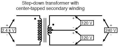
The 120/240 VAC Split phase is "generated" by a center tapped transformer (in general). Something like this:

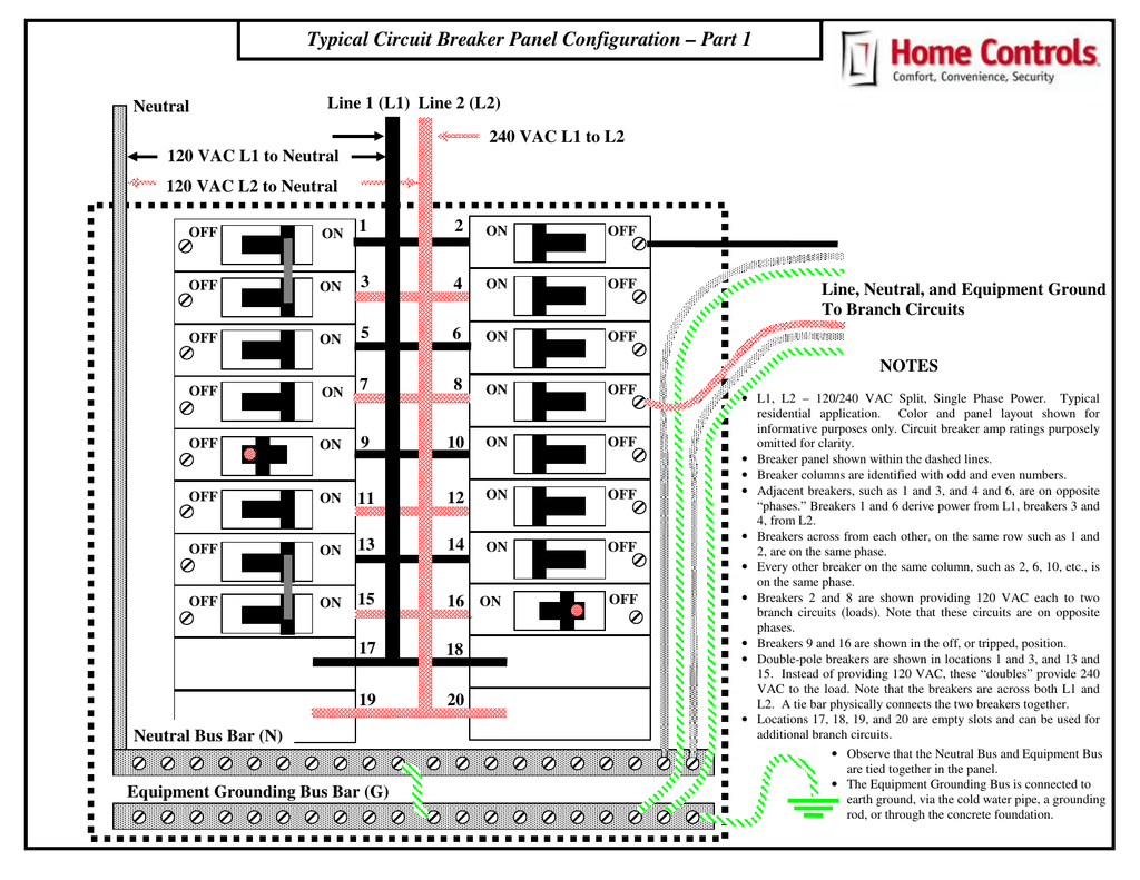
You have 120 VAC only loads that take L1+N or L2+N... You can have 240 VAC loads that take L1+L2 connections (these are usually protected in the main breaker panel with 2-Pole circuit breakers (if one breaker trips because of too much current, their handles are paired together so that second breaker trips too--Killing L1 and L2 power to the loads (safer disconnect).
A 120/240 VAC split phase breaker panel can look like this (schematic):
Note the location of the Ground to Neutral Bond jumper... You have to look closely at your Inverter Manual to make sure you install the Ground to Neutral Bond in the correct location. This gets "messy" because there (may be) a GN bond in the main breaker panel, in the AC output of the Inverter, and in a backup genset (typically larger wattage inverters & generators (>3,000 Watts or so--My guess) can be defaulted with G+N bonds--And in the "operational" home AC wiring, you only want G+N bond in one locations.
This may be addressed by "lifting extra" bonds in AC inverter output and Genset output--Or the inverter may have an internal N+G switch to address the variable locations possible of N+G bonding.
Note that the "breakers" in the above drawing are all single pole breakers--Technically only used for 120 VAC circuits. With 240 VAC circuits, the breakers are in "pairs" (Black and Red) so that the 2 pole breaker will supply power to the 240 VAC load.
When wiring your home/cabin... You have a choice of using 2 wire ROMEX (Black+White+Safety Ground). Used for 120 VAC circits.
And you have the option of using 3 wire ROMEX. Black+Red+White+Ground. You can wire a 240 VAC load (Black+Red) or two 120 VAC circuits (Black+White+ground to one circuit/load; Red+White+ground to second circuit/load).
That is a quick overview... But as always, the details can bite you (I used ROMEX, but there are other wiring methods too such as conduit, etc.).
It is not rocket surgery--But you want to make sure you follow code/good practices to be safe. (other issues such as using GFI outlets near sinks/water/outside. Some locations require Arc Fault breakers in box--Kind of a pain for other reasons).
Feel free to ask more questions--But I am not the Code Guy/Electrician here.
-Bill
Near San Francisco California: 3.5kWatt Grid Tied Solar power system+small backup genset -
In a typical 110/220 breaker panel the breaker you are connecting to it determines whether you get a single phase, 110 Vac or 220 Vac split phase The 220 breaker is a two pole breaker and is connected to both legs instead of a single pole breaker putting out 110 volts. The way the breaker panel is constructed is with one phase buss alternating with the other phase's buss.so when you snap in a 220 breaker into the panel it will grab both buss bars giving you your 220. Sorry for the crude terminology I'm sure someone here can explain it more elegantly.
2.1 Kw Suntech 175 mono, Classic 200, Trace SW 4024 ( 15 years old but brand new out of sealed factory box Jan. 2015), Bogart Tri-metric, 460 Ah. 24 volt LiFePo4 battery bank. Plenty of Baja Sea of Cortez sunshine.
-
BB. said:
you have the option of using 3 wire ROMEX. Black+Red+White+Ground. You can wire a 240 VAC load (Black+Red) or two 120 VAC circuits (Black+White+ground to one circuit/load; Red+White+ground to second circuit/load).
question bill what awg / gauge wire? 10/3( 30 amps) / 8/3 (up to 45amps).
so i want run wire from my inverter to load center. HOnestl i'm thinking 8/3 wire 182.00 cnd plus tax 10 metres.
now i may have a dumb question but i 've done some thinking.
so in the pic your shared with wiring load center i was wondering when i connect a circuit say a small electric heater 1500watts (on it's own circuit)
now
i also run i dunno some other power hungrydevice on separate circuit / say dehumifiyer. so now i have the total of both devices going thru load center back to inverter . you with me so far?
so am i right in buying the 8/3 wire for it's good for up to 45amps. Hope that makes sense?
Ty Neii
-
I am not the code guy here... So others may have other/better answers than I. My first cut:
You have to look at the temperature (environment) and the temperature rating of the wire, etc... For non-ROMEX, this is a basic chart:
https://lugsdirect.com/WireCurrentAmpacitiesNEC-Table-301-16.htm
And ampacity rating for ROMEX (NM cable) is not a "simple answer". There is an "override" for 14/12/10 AWG conductors, and must use 60C insulation rating:
https://forums.mikeholt.com/threads/romex-ampacity-on-a-c-unit.38042/
From first link:
*Section 240.4(D) shall be refrenced for conductor overcurrent protection limitations, except as modified elsewhere in the Code
So 14/12/10 AWG is rated for 15/20/30 amp limit (I never could figure why 240.4(D) basically knocked 5 amps off the wire rating (would have been 20/25/35 in other charts).
It appears that 8 AWG NM is rated for 40 amps max (not 45 amps).
A 1,500 Watt heater:- 1,500 Watts / 115 VAC = 13 amps (roughly).
In the town I grew up in (just south of San Francisco), they have a (non-standard?) requirement all electrical circuits require a minimum of 12 AWG and 20 Amp breakers---The added cost, stiff wire, and room in boxes--Electricians have bad words to say.
The other thing to look at is voltage drop.... More or less, looking at a suggested maximum of 3% voltage drop (0.03 * 115 VAC = 3.45 volt max drop). This is also a ~3% loss of power (1,500 Watts * 0.03 voltage drop = 45 Watts). Typically don't bother trying for less than 1% drop--That is just a lot of copper cost $$$.
Say you want 13 amps @ 115 VAC on a 20 foot @ 14 AWG circuit:
https://www.calculator.net/voltage-drop-calculator.html?necmaterial=copper&necwiresize=0&necconduit=pvc&necpf=1&material=copper&wiresize=0.4066&resistance=1.2&resistanceunit=okm&voltage=115&phase=ac&noofconductor=1&distance=20&distanceunit=feet&eres=13&x=29&y=19&ctype=necResult
Voltage drop: 1.62
So for a 20-40 Foot 14 AWG run, you will be 3% or less voltage drop.
Voltage drop percentage: 1.41%
Voltage at the end: 113.38
You could use 12 AWG (less resistance, less drop), and a 20 Amp breaker--Not unusual (you can get 15/20 Amp sockets at the hardware store)
https://pennaelectric.com/15-amp-vs-20-amp-outlet/
The "T" shape supports both vertical 15 amp and horizontal 20 amp blades.
I have run into very few (maybe none?) "residential" equipment with a 20 amp @ 120 VAC plug.
Note that 14 AWG cable and 15 Amp circuit breakers are rated to "not trip" at 80% of 15 amps (12 amps) and will trip at 100+% of rated current (maybe minutes, hours, or longer).
Most home equipment only runs for minutes or 10's of minutes (blender, mixer, electric heater) and very unlikely to trip at 15 amp current for short periods of time.
Things like a battery charger for your bank--Charging a battery can take hours at max rated charger current/power. So, for "continuous current" applications, the NEC uses an 80% derating. For example a 15 amp input to a battery charger:- 15 amp continuous load * 1/0.80 NEC derating = 18.75 Amps ~ 20 Amp branch circuit (wiring+breaker) suggested
Say you want to power 13 amps (heater) + 12 amps (dehumidifier) = 25 amps total current (just to pick some numbers) for 33 feet (10 meters). And 10 AWG cable rated for 30 amps):
https://www.calculator.net/voltage-drop-calculator.html?necmaterial=copper&necwiresize=2&necconduit=pvc&necpf=1&material=copper&wiresize=0.4066&resistance=1.2&resistanceunit=okm&voltage=120&phase=ac&noofconductor=1&distance=33&distanceunit=feet&eres=25&x=42&y=28&ctype=necResult
Voltage drop: 1.96
Voltage drop percentage: 1.63%
Voltage at the end: 118.04That gives you ~2 volts drop on 10 AWG, and if your 14 AWG circuits are less than 20 feet--Then the total drop is probably less than 3% or 3.45 volt drop.
The dehumidifer may have high starting surge (>600 Watts) but a steady state power draw of less than 150 Watts (for simple/smallish unit).
As always, you should measure your loads if you are going to cut things close (for solar power, don't over size the solar system). A Kill-a-Watt or similar brand meter is very nice to have:
https://www.amazon.com/kill-a-watt/s?k=kill-a-watte
In general, "power hungry" devices are not great loads for off grid solar... Finding the "most efficient" appliances is usually a good idea. Almost always "cheaper to conserve energy than to generate it".
For example, I know that this window A/C unit is very efficient (for a smaller A/C system)--It is inverter based (low surge current, can have low run current). And it has a dehumidify mode. If it would work for your needs--Might be worth looking at:
Their U-Shape units (you can close your window "thru" the unit except fo the last 2 inches or so:
https://www.midea.com/us/air-conditioners/window-air-conditioners
https://forum.solar-electric.com/discussion/355789/midea-u-inverter-window-air-conditioner#latest
Electric heaters do burn a lot of power. A heat pump based mini-split can be upwards of 1/3rd the power vs electric resistance heating:=
https://forum.solar-electric.com/discussion/23007/mini-split-update-for-offgrid/p1
-Bill
Near San Francisco California: 3.5kWatt Grid Tied Solar power system+small backup genset
Categories
- All Categories
- 234 Forum & Website
- 142 Solar Forum News and Announcements
- 1.4K Solar News, Reviews, & Product Announcements
- 200 Solar Information links & sources, event announcements
- 901 Solar Product Reviews & Opinions
- 256 Solar Skeptics, Hype, & Scams Corner
- 22.5K Solar Electric Power, Wind Power & Balance of System
- 3.5K General Solar Power Topics
- 6.7K Solar Beginners Corner
- 1K PV Installers Forum - NEC, Wiring, Installation
- 2.1K Advanced Solar Electric Technical Forum
- 5.6K Off Grid Solar & Battery Systems
- 430 Caravan, Recreational Vehicle, and Marine Power Systems
- 1.1K Grid Tie and Grid Interactive Systems
- 656 Solar Water Pumping
- 817 Wind Power Generation
- 624 Energy Use & Conservation
- 624 Discussion Forums/Café
- 316 In the Weeds--Member's Choice
- 75 Construction
- 125 New Battery Technologies
- 108 Old Battery Tech Discussions
- 3.8K Solar News - Automatic Feed
- 3.8K Solar Energy News RSS Feed
