Add Solar Panels to charge battery bank for inverter

Hello All,
I have a 24v inverter, outback vfx3024 with 200Ah battery bank for now, used as backup when there is a power cut ( frequent in Bangladesh).
I am planning to add solar panels to charge batteries. I have a PWM controller at hand, EPsolar Viewstar VS5048N, spec attached.
I am thinking of buying the panels locally, 4x 150w, 36cell panels, they locally manufactured, spec below.
Peak power = 150 watt: A grade mono crystalline.
Maximum power current(Imp) =8.16 A
Maximum power voltage(Vmp) =18:38v
Short Circuit Current( Isc)=8.81A
I have at my disposal, 6mm2 pv cable to run from the roof of 3 story building to ground floor where the inverter and batteries are located.
I am thinking of 2 panels in series and then parallel, terminate in a combiner box, then to CC. I am worried about voltage drops on the long run from the panels to CC, about 35ft one way.
How best to wire the panels for best performance with what I have?
Do I need a breaker/fuse for each panel or each string?
How to find the best angle without someone changing it or sun tracker?
Any help will be appreciated.

Comments
-
Welcome to the forum Roks1,
Regarding the best angle and direction... Typically it is your latitude of your city for best year round performance. If you need more power in summer, a pointing the array higher (~+15 degrees) to get summer sun works well (suggest a minimum of 5 degree tilt so that rain will wash off dust and leaves). Pointing down towards the horizon (-15 degrees) will get winter sun better.
If you have summer afternoon thunderstorms, pointing the array slightly more east (south easterly), will get you more energy than facing westerly.
If you have several strings of panels, facing some south east and other south west will harvest almost the same energy, and you will get "more hours of sunlight" -- Longer charging times is very nice for lead acid batteries (i.e., instead of 6 hours of charging, closer to 8+ hours of charging time spread out during the day)... Sometimes called "virtual tracking" (vs a real mechanical tracker).
Here is nice/simple website that should work for you:
http://www.solarelectricityhandbook.com/solar-irradiance.html
Regarding wiring, 6mm^2 (USA 10 AWG) -- Longer distances can be a pain--lots of voltage drop. Say you have 8.16 amps per string, and 10 meters (33 feet) one way wire run--The voltage drop would be:
10 AWG:
Voltage drop: 0.54
Voltage drop percentage: 1.85%
Voltage at the end: 28.46
I would not want much more voltage drop than that (perhaps 3% maximum).
If you have longer distances/more current, then looking at an MPPT (maximum power point tracking) solar charge controller would let you use smaller diameter and/or longer cable with less voltage drop. MPPT controllers are more expensive, and there are a lot of "cheap MPPT" controllers that are really PWM (pulse width modulation) type.
With an MPPT controller, you could (for example, depends on specifications of controller and panels), put your panels in series (Vmp-array is now 72 volts and array current is 8.16 amps total--Power=Voltage*Current -- Double the voltage and 1/2 the current = same power).
Generally, 2 panels or 1 panel in series does not need a fuse/breaker. 3 panels or more in parallel, then you need a fuse/breaker per panel.
Using circuit breakers makes it easier to work on your system. You can turn off the array when working on controller. Or if you have 2+ breakers, you can turn off one string at a time to find a "weak performing" set of panels (each string should be the same amount of current).
-Bill
Near San Francisco California: 3.5kWatt Grid Tied Solar power system+small backup genset -
Thanks Bill for your informative post.
I've got load of telecom beakers, rated at 25A 125v DC, think they are Carling or something, I'll put one on each string.
I've got plenty of 6mm2 cable, I could run each string straight to CC or double up from the combiner box, that should help with voltage drop?
If the CC receives 28.46v, will it be enough to charge the battery? ie will the cc boost the voltage 28.8v?
Worst case, the CC says max pv voltage 96v so I should be able to connect 3x 18v panels in ser to get 54v, right?
That solar irridiance calculator is very helpful, but I have flat roof. It states all year round optimal angle is 65degrees from verticle, so I worked our 25degrees from horizontal. Panels facing to the south.
-
The Vmp of your solar panels should be around Vmp~18 volts.
2xVmp gives you around Vmp-array=36 volts. Note that solar panel Vmp voltage falls as the panels get hot (full noon-time sun on a warm day). Worst case, roughly Vmp*0.81 temp derating = 14.58 volts...
The "knee" of the Vmp*Imp curve is rounded. Current will not "stop" if the panels run at 14.58 volts on a hot+sunny day.
-Bill
Near San Francisco California: 3.5kWatt Grid Tied Solar power system+small backup genset -
On the voltage drop calculator, do plug in 36v or 29,16v?
Thanks
-
It depends...
In reality, the % is the voltage drop/bus voltage.
- 0.54 volt drop / 29.0 volts (input to PWM battery charging assuming 0 volt PWM drop) = 0.0186 = 1.86% drop
- 0.54 volt drop / 36 Vmp-array (input to MPPT controller) = 0.015 = 1.5% drop
Same voltage drop in either case--But you really need to look at the "absolute" operating voltages to figure out what is best.
Vmp=~35-36 volts is a 72 cell panel (or 2x 36 cell panels in series--Vmp-cell~0.5 volts per cell). This is usually the average "optimum" for a PWM controller charging a 24 volt lead acid battery bank.
For a MPPT controller, you really should have 1.3 volts * Vbatt for your Vpanel input:
- 1.3 * 29 volts charging = 37.7 volt minimum for charge controller
Assuming 81% working Vmp-hot, then the Vmp-std (standard temperature) for your array with an MPPT controller:
- 1.3 MPPT min voltage * 29 volts nominal battery charging voltage * 1/0.81 Vmp-hot derate = ~46.5 volts Vmp-array-STD
Typically, if you have h "higher end" MPPT controller with Vpanel input max ~ 150 volts, in a very cold climate (Voc and Vmp rise as it gets below freezing), then Vmp-array-std~100 VDC max...
- 100 VDC Vmp-array max / 18 volts Vmp for "12 volt panel" = 5.6 panels in series ~ 5x "12 volt" panels in series maximum
- 3 * 18 volts Vmp-std = 54 volts Vmp-array-min with 3x "12 volt panels" in series.
If you lived on a sunny Caribbean island where it never got below 75F (25C or Standard Temperature) then, your max series array would be:
- 140 VDC (some controller's max input) / 18 Volts Vmp-std = 7.8 ~ 7 panels in series
Sounding like a broken record, the details matter, a lot, for solar power system design.
Some solar charge controller mfg. make programs or websites that let you design a system and check against the Mfg. specifications for proper design:
http://www.midnitesolar.com/sizingTool_kid/index.php (smaller 30 amp Kid controller from Midnite)
http://www.midnitesolar.com/sizingTool/index.php (larger ~80 amp Classic controller from Midnite)
You can do the calculations by hand too... Or put in a spreadsheet to make things easier (and you cannot make any mistakes).
Also, look at the size of your array (Watts) and what type of panels are best for you... "12 volt" solar panels (in the USA) tend to run around $2 per Watt (~140 Watt or smaller panels). They are smaller and easier to ship.
And there are panels that are used for larger solar installations (Grid Tied Systems typically)--These are ~200 Watts and above, and have Vmp-array in the 30-36 volt, or higher, range. And tend to be less than $1 per Watt. These are pretty good size, and need to be shipped on pallets to be cost effective and not broken in shipment.
For solar power systems, typically smaller systems (400 Watt or smaller array), tend to be "cheaper" with 12 volt panels (expensive) and PWM controllers (cheap).
For solar power systems that are larger (typically >800 Watts), for various reasons, MPPT controller systems and GT panels are cheaper (MPPT controller more expensive, >200 Watt panels are cheaper)--Plus with MPPT systems, you can mount the solar array farther away from the charge controller.
DO NOT BUY ANY HARDWARE YET until you have done a full pencil and paper design (probably a few of them). There are specific solar panels (Vmp~50-80 volts) that do not work with a 48 VDC battery bank. Do your research and design(s) first, then buy the hardware based on what is available in your local area (and/or what you can cost effectively ship/carry as personal baggage on the airliner)
-Bill
Near San Francisco California: 3.5kWatt Grid Tied Solar power system+small backup genset -
Hi Bill,
Thank you again for the informative post, I like these kind of broken record 😃.
I can carry small items with me but the panels I'll have to get locally, its about $0.50 per watt.
I've not bought anything substantial yet, the CC, cables, breakers got for knock down price, chap was clearing shop.
For the time being its going to be a 600w or of panels.
-
One more question,
would it be of any benefit (electrically) to contain the cables between panel and controller in side a conduit pipe? or is that going to create heat and mate it worse?
-
Placing cables in conduit--Keeps the sun and weather off them. But it also lowers heat transfer and cables run hotter (In the US, our electrical code has deratings for this). It "forces" you to use higher temperature insulation and/or larger diameter copper cable.
If you have lightning in your area, metal conduit can also reduce the effects of a nearby strike.
And, if you have lots of little creatures that chew--Building nests under solar arrays and eating wire insulation is a common issue that needs to be addressed.
Metal conduit can also reduce radio frequency noise too... Very handy if you are a HAM (amateur radio) operator.
-Bill
Near San Francisco California: 3.5kWatt Grid Tied Solar power system+small backup genset -
No codes round here 🙂, I dont thing I'll be using metal pipes, maybe the pvc pipes, will see.
These cables are PV cables, made in UK rated at 90'c, so should cope with 40'c odd in the summer months in Bangladesh.
Thanks.
-
Regarding earthing, can I run a bare copper wire from the panels to the earth bus bar at the inverter or do I need a dedicated earthing?
Like I said there is no code requirements solar panels, just for my peace of mind.
Thanks.
-
Do you have lightening there? If so I would run a bond wire from panel to panel then down the outside of the dwelling to a good earth ground. Lightening is the biggest danger with aluminum framed low voltage panels and systems. Maybe 6 ga wire and an 8 foot copper coated ground rod. But that's the standard for U.S. , but I do not know what is required or is the practice there. You don't want to invite the lightening inside!
2 Classic 150, 2 Kid, 5 arrays 7.5 kw total 2ea. 2S6P Sharp NE-170/NE-165, 1ea. 12P Sanyo HIT 200, 2ea. 4/6P Sanyo HIT 200, MagnaSine MS4024AE, Exeltech XP-1100, 2 Banks L-16 battery, Rolls-Surette S-530 and Interstate Traction, Shunts with whizbangJr and Bogart Tri-Metric, iCharger i208B dc-dc buck/boost converter with BMS for small form lithium 8S 16650 or LiFePO4, -
Hi Tecnodave,
There is an burried earth rod and the copper wire runs to the meter outside the house.
Can I attach the earth from the panels to this earth block next to the meter?
Or do I need a seperate earth rod?
There is not requirement locally.
-
Can you run the ground cable from the array to the ground rod straight down?
If you have to do a horizontal run, the longer the run, the more likely the lightning will leave the cable and find another easy to earth (lightning will follow 6 AWG cable not much more than 10 feet or so).
If you do need a second behind rod, connect a 6 AWG cable between the two ground rods (for 120/240 vac safety grounding of any short circuits).
Bill
Near San Francisco California: 3.5kWatt Grid Tied Solar power system+small backup genset -
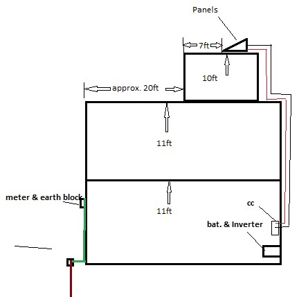
No, the meter is at the front of the house and the panels will be at the rear, on the roof of the stair case room (you could call it 3floor).
I've done a very rough sketch of where things are located, measurements are approximate.
-
Roks1
take your panels ground straight to the ground as close as possible. Lightening will jump off a bend! Use big radaii to bend the wire. There should be no need to bond the array ground to the AC ground as no AC is at the panel array.
2 Classic 150, 2 Kid, 5 arrays 7.5 kw total 2ea. 2S6P Sharp NE-170/NE-165, 1ea. 12P Sanyo HIT 200, 2ea. 4/6P Sanyo HIT 200, MagnaSine MS4024AE, Exeltech XP-1100, 2 Banks L-16 battery, Rolls-Surette S-530 and Interstate Traction, Shunts with whizbangJr and Bogart Tri-Metric, iCharger i208B dc-dc buck/boost converter with BMS for small form lithium 8S 16650 or LiFePO4, -
There is DC power in both the array and the home (j-boxes, conduit, etc.).
And most DC and AC power systems in north America are ground referenced. And few (if any) solar charge controllers are isolated between Vpanel and Vbatt.
For example if Varray + is shorted to the array mounting, a person could get electrocuted if they walk in wet grass and touch the array mounting frame.
Tying the array ground rod to the home's ac&dc ground rod would short the + array cable to DC ground.
Earth ground does not have low enough resistance to do this.
Bill
Near San Francisco California: 3.5kWatt Grid Tied Solar power system+small backup genset -
Thanks for the input guys, just realised I did not attach the artful picture.
So basically I need a separate earth rod close to the panels...ie straight as possible run/drop from the panels.
Or have I got this all wrong 😀
-
That's how mine is done. I really ought to tie the array ground plate to the cabin plate, but the ground is really rocky and the array isn't reachable by someone walking in wet grass.
The wire runs off the left edge of the structure:
Off-grid.
Main system ~4kw panels into 2xMNClassic150 370ah 48v bank 2xOutback 3548 inverter 120v + 240v autotransformer
Night system ~1kw panels into 1xMNClassic150 700ah 12v bank morningstar 300w inverter -
-
My suggestion... One rod at the base of the array, (and surge protection in box where DC wiring enters the home). Run 6 AWG between all ground rods.
https://www.solar-electric.com/search/?q=surge+protection
-Bill
PS, I should add running a 6 AWG minimum from battery ground bus to nearest ground rod too.
Near San Francisco California: 3.5kWatt Grid Tied Solar power system+small backup genset -
And, a general warning. Most PSW/TSW (pure/true sine wave) inverters have an isolated AC output which can have the "neutral" ground bonded/ground referenced.
And most MSW (Modified sine/square wave) inverters do not have isolated AC output. And you cannot ground reference one of the AC outputs and the DC negative bus... That creates a short circuit through the AC inverter's switching transistors--And will ruin the inverter.
-Bill
Near San Francisco California: 3.5kWatt Grid Tied Solar power system+small backup genset


Categories
- All Categories
- 234 Forum & Website
- 142 Solar Forum News and Announcements
- 1.4K Solar News, Reviews, & Product Announcements
- 200 Solar Information links & sources, event announcements
- 901 Solar Product Reviews & Opinions
- 256 Solar Skeptics, Hype, & Scams Corner
- 22.5K Solar Electric Power, Wind Power & Balance of System
- 3.5K General Solar Power Topics
- 6.7K Solar Beginners Corner
- 1K PV Installers Forum - NEC, Wiring, Installation
- 2.1K Advanced Solar Electric Technical Forum
- 5.6K Off Grid Solar & Battery Systems
- 430 Caravan, Recreational Vehicle, and Marine Power Systems
- 1.1K Grid Tie and Grid Interactive Systems
- 656 Solar Water Pumping
- 817 Wind Power Generation
- 624 Energy Use & Conservation
- 624 Discussion Forums/Café
- 316 In the Weeds--Member's Choice
- 75 Construction
- 125 New Battery Technologies
- 108 Old Battery Tech Discussions
- 3.8K Solar News - Automatic Feed
- 3.8K Solar Energy News RSS Feed