I need help about cut-off voltage, Wire length and size from CC to battery
ausman
Registered Users Posts: 3 ✭
I have got 150 AH Flooded lead acid battery, 2x180 watts solar panels and a 40A EP Solar 4210 RN MPPT charge controller. The controller is an old model which doesn't have any custom settings. You have to select one of the three predefined settings for your specific battery. The screenshot is attached from the manual for better elaboration.
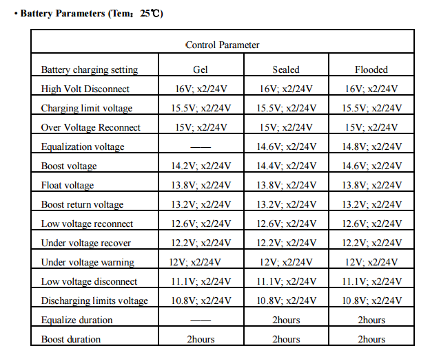
After reading all about the lead acid battery, I am really confused what should be the optimum cut-off voltage, especially in the case where I can't manually change the settings. From cut-off voltage, I mean the absorption voltage / boost voltage. Some experts say it should be 14.4 volts, some say 14.6 as it is mentioned the same in the manual, and some say it should be 13.8. Some say if you want to get the maximum output from the battery it should be charged above 14.8, while others say it causes corrosion. According to this article, corrosion is more dangerous than sulfation and corrosion can only be avoided if we don't overcharge the battery.
Another thing which I want to know about is the wire length and size coming from the charge controller to the battery. What should be optimum length and size of the wire and what happens if we attach a long wire from charge controller to the battery?? One thing is for sure that the voltage at the battery terminal will drop but how much is dependent on many factors. Now the main question is how Charge controller handles this voltage drop?? I am asking this question because I want to lower the absorption voltage for the battery from 14.6 to 14.3 or 14.2 to minimize the corrosion and I can't manually change the voltage parameters from my charge controller.
After reading all about the lead acid battery, I am really confused what should be the optimum cut-off voltage, especially in the case where I can't manually change the settings. From cut-off voltage, I mean the absorption voltage / boost voltage. Some experts say it should be 14.4 volts, some say 14.6 as it is mentioned the same in the manual, and some say it should be 13.8. Some say if you want to get the maximum output from the battery it should be charged above 14.8, while others say it causes corrosion. According to this article, corrosion is more dangerous than sulfation and corrosion can only be avoided if we don't overcharge the battery.
Expressed in volts per cell, corrosion of the positive grids is for all intents and purposes zero below 2.15 volts. Corrosion proceeds extremely slowly at 2.25 volts. It becomes noticeable at 2.35 volts, more noticeable at 2.45 volts and significant at 2.55 volts. Corrosion becomes pronounced above 2.65 volts.
Another thing which I want to know about is the wire length and size coming from the charge controller to the battery. What should be optimum length and size of the wire and what happens if we attach a long wire from charge controller to the battery?? One thing is for sure that the voltage at the battery terminal will drop but how much is dependent on many factors. Now the main question is how Charge controller handles this voltage drop?? I am asking this question because I want to lower the absorption voltage for the battery from 14.6 to 14.3 or 14.2 to minimize the corrosion and I can't manually change the voltage parameters from my charge controller.
Tagged:
Comments
-
The problem with using resistance (a long wire) to achieve voltage drop is that the voltage drop will be negligible as the charging current tapers off during absorb. The battery will get to the same high voltage, but it will take longer to get there and it will spend less time at that high voltage.
Don't get too phobic about high voltage... you do need to stir the electrolyte every week or so to prevent stratification. Stratification will cause both sulfation and corrosion.
--vtMaps
4 X 235watt Samsung, Midnite ePanel, Outback VFX3524 FM60 & mate, 4 Interstate L16, trimetric, Honda eu2000i -
If it stirs the electrolyte after a week, i would be happy. But it does so everyday for 2 hours.
Can't i use a diode to lower the voltage?? I was just reading about diodes so am asking here. -
No--More than likely adding a diode will just confuse the controller even more (controller may not turn on or could even select wrong battery voltage with diode in series. You would need to run a resistor to bypass the diode to (probably) wake the controller up.
What voltage do you see on the battery bank for those 2 hours? While not ideal, 2 hours at 14.6 volts is not the worst thing. And equalize at 14.8 volts is not usually high enough to be a "real problem" (equalize for a few hours per month, not 2 hours per day).
If your controller is not doing what you need--Then purchasing a new brand may be your next choice if your battery is being over charged.
-Bill
Near San Francisco California: 3.5kWatt Grid Tied Solar power system+small backup genset
Categories
- All Categories
- 233 Forum & Website
- 140 Solar Forum News and Announcements
- 1.3K Solar News, Reviews, & Product Announcements
- 181 Solar Information links & sources, event announcements
- 894 Solar Product Reviews & Opinions
- 252 Solar Skeptics, Hype, & Scams Corner
- 22.5K Solar Electric Power, Wind Power & Balance of System
- 3.5K General Solar Power Topics
- 6.7K Solar Beginners Corner
- 1K PV Installers Forum - NEC, Wiring, Installation
- 2.1K Advanced Solar Electric Technical Forum
- 5.6K Off Grid Solar & Battery Systems
- 428 Caravan, Recreational Vehicle, and Marine Power Systems
- 1.1K Grid Tie and Grid Interactive Systems
- 656 Solar Water Pumping
- 816 Wind Power Generation
- 621 Energy Use & Conservation
- 623 Discussion Forums/Café
- 316 In the Weeds--Member's Choice
- 74 Construction
- 125 New Battery Technologies
- 108 Old Battery Tech Discussions
- 3.8K Solar News - Automatic Feed
- 3.8K Solar Energy News RSS Feed