OutBack Flexmax Solar Controller Wiring Question

56Nomad
Registered Users Posts: 7 ✭
Hello all,
I’m almost finished with my solar installation on my Class A motorhome. On the roof of my motorhome there are (3) 300 Watt Panels (rated current 8.26 Amps, rated voltage 36.6 Volts). From those solar panels are the #10 wires that come down to breakers in the solar combiner box.
I purchased an Outback FLEXmax 80 solar controller and it was recommended that I also purchase and install the the OutBack PV Ground-Fault Detector Interupter (PNL-GFDI-80) and the OutBack Panel Mount Breaker/Switch (PNL-80-DC)
If anyone has good knowledge of these Outback products, would you be kind enough to advise me if my wiring diagram below is correctly wired. I also attached the OutBack schematic for the OutBack PV Ground-Fault Detector Interupter (PNL-GFDI-80)
Many thanks!
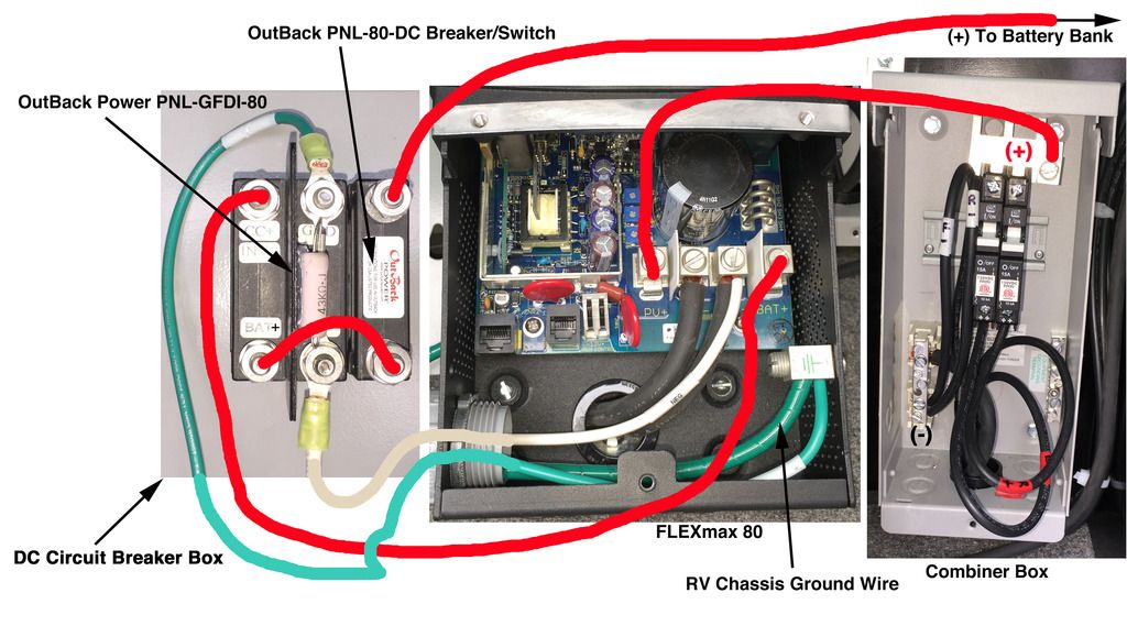

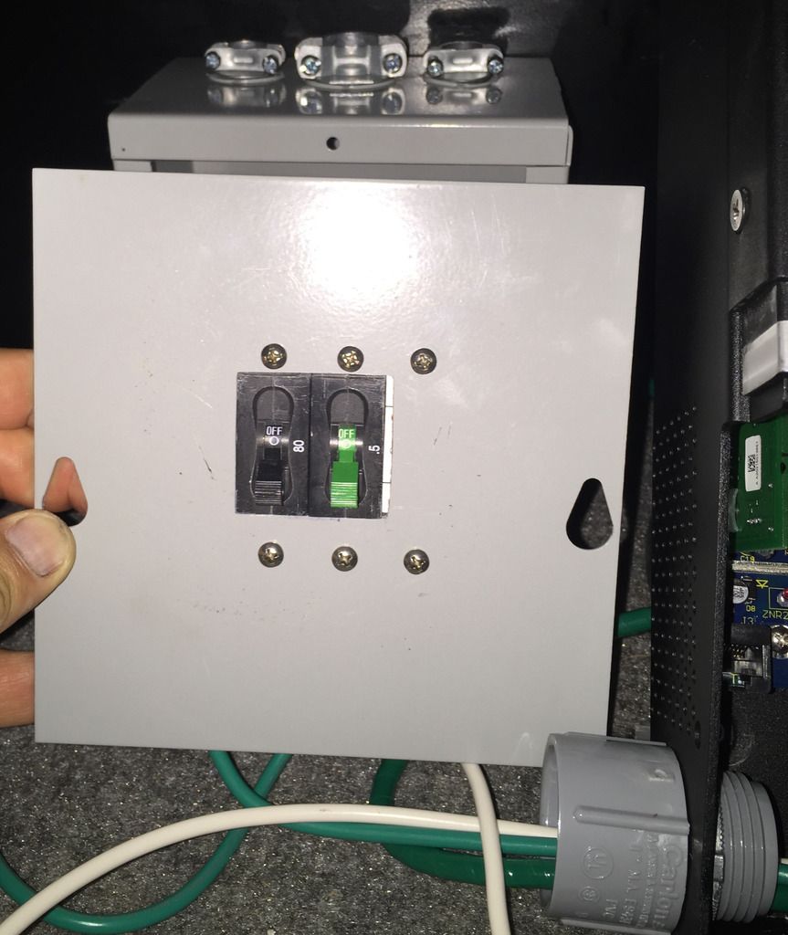
Here is a photo of the front of the mounted OutBack PV Ground-Fault Detector Interupter (PNL-GFDI-80) and the OutBack Panel Mount Breaker/Switch (PNL-80-DC)
I’m almost finished with my solar installation on my Class A motorhome. On the roof of my motorhome there are (3) 300 Watt Panels (rated current 8.26 Amps, rated voltage 36.6 Volts). From those solar panels are the #10 wires that come down to breakers in the solar combiner box.
I purchased an Outback FLEXmax 80 solar controller and it was recommended that I also purchase and install the the OutBack PV Ground-Fault Detector Interupter (PNL-GFDI-80) and the OutBack Panel Mount Breaker/Switch (PNL-80-DC)
If anyone has good knowledge of these Outback products, would you be kind enough to advise me if my wiring diagram below is correctly wired. I also attached the OutBack schematic for the OutBack PV Ground-Fault Detector Interupter (PNL-GFDI-80)
Many thanks!


Here is a photo of the front of the mounted OutBack PV Ground-Fault Detector Interupter (PNL-GFDI-80) and the OutBack Panel Mount Breaker/Switch (PNL-80-DC)

Comments
-
According to these drawings:
http://www.outbackpower.com/downloads/documents/wiring_diagram/North_American_FP2_Grid-tie_with_single_inverter.pdf
http://www.outbackpower.com/downloads/documents/1401103030655Ground_Fault_Detector_Interrupter_REV_A.pdf
You do not need to use the second circuit breaker unless you have a second charge controller. Also, as per your drawing, NEC 2008 and beyond says to put the DC GFCI between controller and battery bank (as you have yours wired--per second link above).
First--I believe the the DC GFCI as implemented is unsafe (can discuss, if you wish).
Second, in general, don't put two cables (battery negative and DC GFCI) cables into one connector on the charge controller. Find a different place (like the DC Return Bus) to put the DC GFCI sense connection.
I will note that there are issues with many DC circuit breakers in that they are polarity sensitive when they break (open). Having a second breaker wired "backwards" to the first can be a solution for using two polarized breakers in a DC application (I just don't know if this is Outback's solution).
-BillNear San Francisco California: 3.5kWatt Grid Tied Solar power system+small backup genset -
According to these drawings:
http://www.outbackpower.com/download...e_inverter.pdf
http://www.outbackpower.com/download...pter_REV_A.pdf
You do not need to use the second circuit breaker unless you have a second charge controller. Also, as per your drawing, NEC 2008 and beyond says to put the DC GFCI between controller and battery bank (as you have yours wired--per second link above).
First--I believe the the DC GFCI as implemented is unsafe (can discuss, if you wish).
Second, in general, don't put two cables (battery negative and DC GFCI) cables into one connector on the charge controller. Find a different place (like the DC Return Bus) to put the DC GFCI sense connection.
I will note that there are issues with many DC circuit breakers in that they are polarity sensitive when they break (open). Having a second breaker wired "backwards" to the first can be a solution for using two polarized breakers in a DC application (I just don't know if this is Outback's solution).
-Bill
Thanks Bill,
Since I'm not connecting this system to an inverter nor do I have a second charge controller, and in light of your comments, do you think I can make this a safe system by simply removing the OutBack PV Ground-Fault Detector Interupter (PNL-GFDI-80) and just rely on the OutBack Panel Mount Breaker/Switch (PNL-80-DC)?
Howard
-
One thing to verify is the 80 Amp circuit breaker rating... Typically for standard circuit breakers, an 80 Amp breaker would be reated for:
- 80 * 1/1.25 NEC derating = 64 amps maximum continuous branch circuit
http://www.outbackpower.com/outback-products/integration-hardware/item/panel-mount- Panel mounted hydraulic-magnetic type breakers
- Rated for 100% continuous duty cycle
- Not affected by high ambient temperatures
- Non-polarized for use in any wiring orientation
- Can be used for input, output or load circuits
- Contact OutBack for additional information
For example, if 100% of rated current:- 80 amps * 1.25 NEC derating = 100 Amp rated branch circuit wiring.
Regarding DC GFCI--My personal preference is to hard ground the DC battery negative (return) Bus to the chassis ground on the RV. Otherwise, you should use two pole breakers (hot/return) on all DC power leads. Dual breakers are really needed for proper fire/over current safety on "floating" power supplies. But few people do that.
The problem is a single short circuit (say Battery + to chassis ground) now turns the floating system into a positive ground system. And if you have one breaker/fuse in the positive lead, it means that all negative leads now have no protection. If there is one more short circuit (negative to ground in an LED wiring run, for example, you now have a good chance of starting a fire in that unfused run).
Small systems, tend to float and "don't care". But if you have a large battery bank, short circuits scare me (100's to 1,000's of amps into a dead short). Fuses & Breakers, properly installed, help me to sleep at night.
-Bill
Near San Francisco California: 3.5kWatt Grid Tied Solar power system+small backup genset -
Bill,
What you said is really way over my head .. I’'m OK with simpler wiring, but this project now has me stumped.
Believe it or not, Outback does not include the owners manual with their products as they claim to be a green company. Instead, they give you a “cheat sheet” which is shown below in the second attachment. I just went online to see the owners manual and found this installation diagram for my FLEXmax 80 charge controller. Using that diagram, they do not show the need for the Ground-Fault Detector Interupter (PNL-GFDI-80). I'd love to return it as it was a $52 item.
Would you recommend using (2) Breaker/Switches (PNL-80-DC) and not using the GFDI (PNL-GFDI-80)?
Also, could you show me what a “shunt” as illustrated in the owners manual diagram? And, do I really need a shunt?
Thanks
Owners Manual Installation Diagram: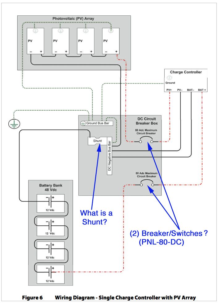
Quick Start Guide Diagram (cheat sheet):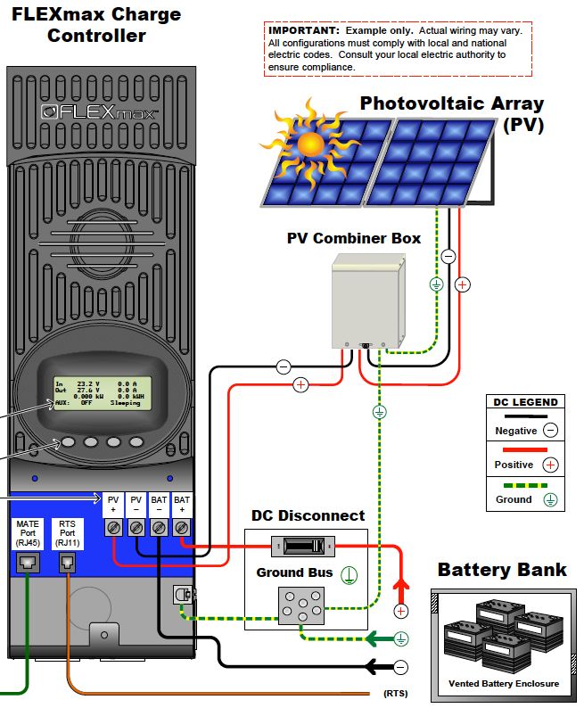
Am I getting closer?: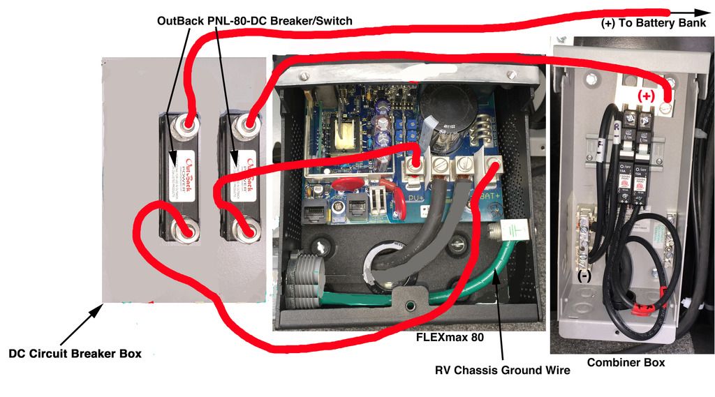
-
Hi Nomad..,
I am not Bill, but here is a pic of a common Shunt used in battery systems:
http://www.solar-electric.com/batteries-meters-accessories/metersmonitors/mkb-500-50.html
A Shunt is a precision very low resistance resistor that allows measuring currents. In the case of battery-based systems, it allows on to monitor current flowing into and out the battery. It can be very useful, and is an essential part of a good Battery Monitor, but not really essential for all battery power systems.
Vic
Off Grid - Two systems -- 4 SW+ 5548 Inverters, Surrette 4KS25 1280 AH X2@48V, 11.1 KW STC PV, 4X MidNite Classic 150 w/ WBjrs, Beta KID on S-530s, MX-60s, MN Bkrs/Boxes. 25 KVA Polyphase Kubota diesel, Honda Eu6500isa, Eu3000is-es, Eu2000, Eu1000 gensets. Thanks Wind-Sun for this great Forum. -
I worked with my solar dealer and we decided that I did not need to use the OutBack PV Ground-Fault Detector Interupter (PNL-GFDI-80) so this is the final solution to what I will be doing........
-
The breaker from the Solar Combiner Box to the Charge Controller Vpanel input is redundant... You really don't need it (you can keep it if that single breaker is easier to access than the combiner box is if you need to service the system).
-BillNear San Francisco California: 3.5kWatt Grid Tied Solar power system+small backup genset


Categories
- All Categories
- 229 Forum & Website
- 136 Solar Forum News and Announcements
- 1.3K Solar News, Reviews, & Product Announcements
- 179 Solar Information links & sources, event announcements
- 892 Solar Product Reviews & Opinions
- 252 Solar Skeptics, Hype, & Scams Corner
- 22.5K Solar Electric Power, Wind Power & Balance of System
- 3.5K General Solar Power Topics
- 6.7K Solar Beginners Corner
- 1K PV Installers Forum - NEC, Wiring, Installation
- 2.1K Advanced Solar Electric Technical Forum
- 5.6K Off Grid Solar & Battery Systems
- 428 Caravan, Recreational Vehicle, and Marine Power Systems
- 1.1K Grid Tie and Grid Interactive Systems
- 655 Solar Water Pumping
- 816 Wind Power Generation
- 620 Energy Use & Conservation
- 622 Discussion Forums/Café
- 316 In the Weeds--Member's Choice
- 74 Construction
- 125 New Battery Technologies
- 107 Old Battery Tech Discussions
- 3.8K Solar News - Automatic Feed
- 3.8K Solar Energy News RSS Feed