My 7.5kWh micro Inverter (Build In Progress)
Comments
-
Re: My 7.5kWh micro Inverter (Build In Progress)
Reason why bare copper is used: it's cheaper.
Normally that's all there is to it. Why use insulation if it's not needed? Ground wires carry zero current unless something goes wrong, then they are expected to carry full current just long enough to trip the circuit protection.
Weird thing: NEC allows the use of metal conduit as a ground conductor, despite the fact it can come loose at junctions and be a poor conductor as a result. Oh but if you splice a ground wire it has to be a 'permanent' splice.
Above all else any wiring has to pass inspection by whomever is doing the inspecting, and they can have different interpretations of the same rules. -
Re: My 7.5kWh micro Inverter (Build In Progress)
There are a few methods for GEC .
enphase shows a diagram of GEC 6AWG coming into the nearest weather proof rain box. However if you chose to do that method then material and install costs rise because the conduit has to be up sized to fit 6awg, and once in the box then you have to use 6awg stranded because you can't pull solid bare through 100' plus of conduit, it's labor intensive and almost close to impossible.
So when installing the GEC I tend to install to the exterior of the IMC conduit, and zip tie the 6 AWG bare solid to pipe with stainless steel straps so there is continuity through out the entire run to ground electrode/service panel/conduits/solar racking. Stainless steel zip ties save a lot of critical installation rather than pulling wire that gauge size. -
Re: My 7.5kWh micro Inverter (Build In Progress)
 I must not be understanding this as there is no reason to specify 6 AWG ground conductor on what is a <20 Amp branch circuit. Sounds like bureaucrats got their fingers in the design again.
Or is the 6 AWG specified for panel frame/mount grounding? In that case I'd do exactly as you describe - but then I'd make the inspectors mad and take that ground directly to an Earthing rod outside the building. -
Re: My 7.5kWh micro Inverter (Build In Progress)Cariboocoot wrote: » I must not be understanding this as there is no reason to specify 6 AWG ground conductor on what is a <20 Amp branch circuit. Sounds like bureaucrats got their fingers in the design again.
Or is the 6 AWG specified for panel frame/mount grounding? In that case I'd do exactly as you describe - but then I'd make the inspectors mad and take that ground directly to an Earthing rod outside the building.
6awg is for racking/panel GEC.
Enphase shows a diagram of racking and panel GEC into rain proof box. It's deceptive looking at the diagram. Because inverter system ground is 12AWG, yet following code racking/panel is 6awg.
The non IG micro inverters require a 6 or 8awg install based on local jurisdiction, but this method can as well be bypassed using Wiley electronic weebs between rack and inverter. -
Re: My 7.5kWh micro Inverter (Build In Progress)
Thanx solar_powered
So the enphase install plan page 41 showing the Green (I assumed bare copper) lines running from panel to panel and inverter and then running to ground is not necessary technically as the inverter is already grounded. So if you ground panels and racking to inverter technically that is what the diagram is showing? Not running the bare copper to junction box & ground?
http://enphase.com/global/files/M215_Installation_Manual_NA.pdf -
Re: My 7.5kWh micro Inverter (Build In Progress)Thanx solar_powered
So the enphase install plan page 41 showing the Green (I assumed bare copper) lines running from panel to panel and inverter and then running to ground is not necessary technically as the inverter is already grounded. So if you ground panels and racking to inverter technically that is what the diagram is showing? Not running the bare copper to junction box & ground?
http://enphase.com/global/files/M215_Installation_Manual_NA.pdf
lets simplify your question. Are your inverters IG or non IG?
non IG inverters will have a ground lug on the top of the inverters that requires you to continuously ground each inverter to the racking system. -
Re: My 7.5kWh micro Inverter (Build In Progress)
They are M215-60-2LL-S22. No integrated ground. They do have a ground lug on top. -
Re: My 7.5kWh micro Inverter (Build In Progress)
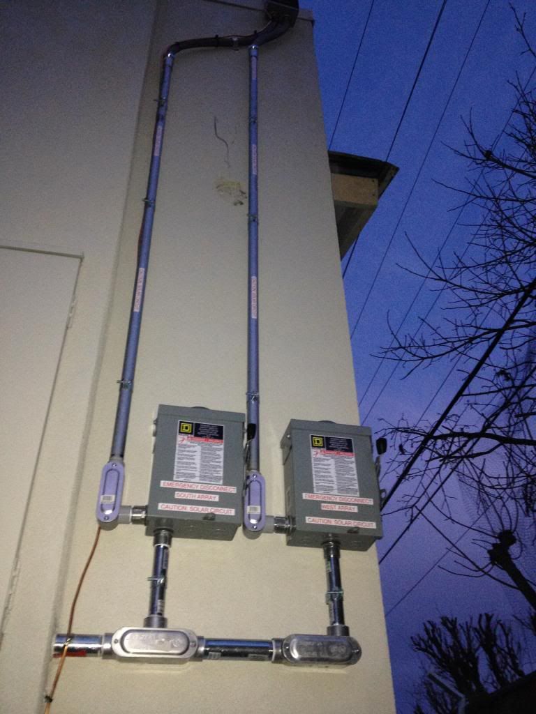
O.K so your connection should look like it does in this pic for GEC grounding.
As you can see the solid 8 and 4awg are separated from the 12awg AC "branch" ground which is in the conduit.
As you can see I said 4awg, reason being they are 2 disconnects, 2 separate systems, so according to code, if 6awg is the bare minimum, I would of had to use double as the call out in the code is 6awg "per" system ground, and I can run a continuous 4awg with no questions from inspectors or PG&E about the minimum code rule.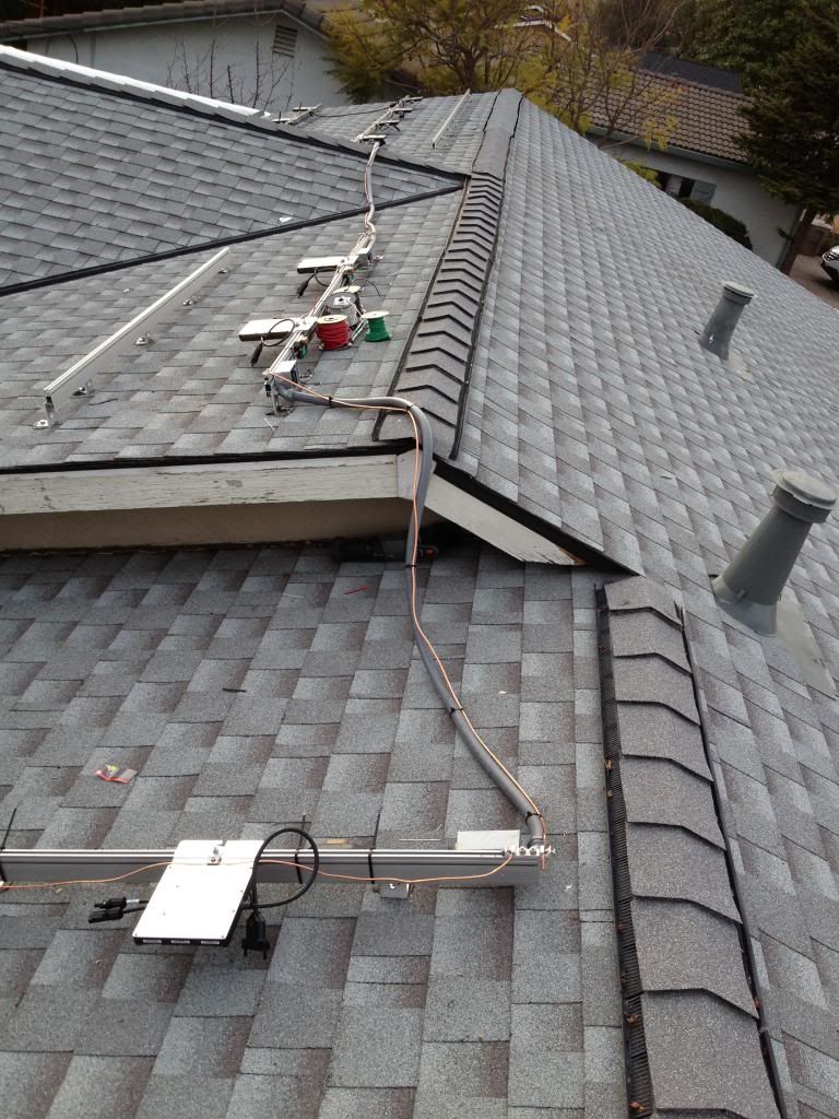
-
Re: My 7.5kWh micro Inverter (Build In Progress)
Rhetorical question*: How did they arrived at that ground wire sizing (since technically it is much larger than it actually needs to be)?")
*One that neither expects nor requires an answer. -
Re: My 7.5kWh micro Inverter (Build In Progress)
Thanx. That makes sense. Bare copper it is.
Much appreciate your knowledge. -
Re: My 7.5kWh micro Inverter (Build In Progress)Cariboocoot wrote: »Rhetorical question*: How did they arrived at that ground wire sizing (since technically it is much larger than it actually needs to be)?
*One that neither expects nor requires an answer.
Not that this is an answer. But I think you hit the nail on the head with the posed discussion of the lightening arrestor a few weeks back, I believe enphase does what they do to argue the warranty.
Hypothetically once the inverter makes contact with the rack (hypothetically) it is grounded.
As for use of my 4awg, I was tired of arguing with jurisdictions of installing more 6awg than needed, and getting delays for finals having to run more 6awg than needed, so for 2 or more systems I just run 4 awg, and it saves me the headache. Stupid reasoning but for some purpose to the madness, it ends stupid political debates that become controversial for the AHJ, and inspectors that have no engineering clue how things work. -
Re: My 7.5kWh micro Inverter (Build In Progress)SolarPowered wrote: »As for use of my 4awg, I was tired of arguing with jurisdictions of installing more 6awg, and getting delays for finals having to run more 6awg than needed, so for 2 or more systems I just run 4 awg, and it saves me the headache. Stupid reasoning but for some purpose to the madness, it ends stupid political debates that become controversial for the AHJ, and inspectors that have no engineering clue how things work.
Talk about hitting the nail on the head ...
-
Re: My 7.5kWh micro Inverter (Build In Progress)Cariboocoot wrote: »Talk about hitting the nail on the head ...
I've come to the realization that for the extra .18 per foot of 4awg VS the 6awg, it not only saves me the headache of arguing with jurisdictions and utilities, it ultimately has saved me an average of $260 that would come out of my pocket to run that extra 6awg bare, wait for finalization, final payment, the time, money, labor, and a dissatisfied client waiting to energize. These can be a very discouraging feelings. 4awg is my savior. -
Re: My 7.5kWh micro Inverter (Build In Progress)
Plus if the array should suddenly produce 150 Amps current dead short into the frames .... <JOKE -
Re: My 7.5kWh micro Inverter (Build In Progress)Cariboocoot wrote: »Plus if the array should suddenly produce 150 Amps current dead short into the frames .... <JOKE
No really though thats what inspectors believe. Just like they don't know a spec for a 200 amp breaker when it calls out for 10,000 amp RMS SYM and there fore tell me that is the reason why they want my breakers installed at the very bottom of the distribution panel instead of the top of the distribution. They believe in mythical dragons..... Seriously -
Re: My 7.5kWh micro Inverter (Build In Progress)SolarPowered wrote: »...and there fore tell me that is the reason why they want my breakers installed at the very bottom of the distribution panel instead of the top of the distribution. They believe in mythical dragons..... Seriously
That's because we all KNOW that solar power is more efficient traveling uphill since it comes from the sun and heat rises. <JOKEOff-Grid in Central Florida since 2005, Full-Time since June 2014 | 12 X Sovello 205w panels, 9 X ToPoint 220w panels, 36x ToPoint 225w panels (12,525 watts total) | Custom built single-axis ground mounts | Complete FP2 Outback System: 3 x FM80, 2 x VFX3648, X240 Transformer, FLEXnet-DC, Mate-3, Hub-10, FW500 AC/DC | 24 x Trojan L16RE-B Batteries 1110ah @ 48v | Honda EU7000is Generator and a pile of "other" Generators | Home-Made PVC solar hot water collector | Custom data logging software http://www.somewhatcrookedcamp.com/monitormate.html -
Re: My 7.5kWh micro Inverter (Build In Progress)
Solar powered,
One final question as I come down the stretch to finish my wiring. See the picture above.
Do I have to have 2 separate disconnects for separate strings?
Can I combine them at my 60 AMP 2 pole Disconnect?
Do I then put a (2)x20 amp fuse in the 60 amp disconnect on each pole?
Then on to a single 40amp 2 pole breaker in my panel?
http://www.affordable-solar.com/store/ac-dc-disconnect-enclosures/d222nrb-60-amp-safety-switch
This is the disconnect I have purchased and installed. -
Re: My 7.5kWh micro Inverter (Build In Progress)
I just have to say this.
No home without solar is required to have a disconnect for the grid power. But put solar on the roof and suddenly it's not safe. If there were a disconnect for the grid power all you have to do is shut that down and the standard GTI system will stop functioning. It makes no difference if it were a central inverter or micro inverters. Technically, killing the grid feed will bring down either type of inverter; no additional disconnect is needed. Disconnecting the array is therefor redundant in such cases.
If it is a hybrid or off-grid inverter it would need an accessible battery disconnect (I know: don't give them any ideas). That is the only way to shut one of those down so that nothing in the house is powered.
Moreover, merely disconnecting the array(s) from whatever type of inverter doesn't stop the arrays from outputting power; you could still have 300+ Volts in the wiring on the roof.
Some of these regulations are stupid. They are written by people who do not understand what they are dealing with. They add no real amount of safety. They do add to the price and hassle of installation. -
Re: My 7.5kWh micro Inverter (Build In Progress)Cariboocoot wrote: »I just have to say this.
No home without solar is required to have a disconnect for the grid power.
Isn't that what the breaker box is for (among other things)? -
Re: My 7.5kWh micro Inverter (Build In Progress)
The original requirement was for an AC disconnect between the GT inverter and the AC main panel.
The Utilities did not trust that the GT inverters would shut down if the grid went away (protect their linemen). It was not a "requirement" that you had an AC disconnect on the outside/accessable wall... It was just that the utility reserved the right to pull/lock off your main meter. Thought being you would rather go without solar power vs loss of power to the whole home.
Now, with new codes/inverter design requirements, many utilities are dropping the AC disconnect requirement.
However, there are new requirements for fire safety around the array (access to the roof to ventilate in case of fire), panel disconnects to reduce chances of arc faults/fires/etc.
Are they better--Sometimes it is debatable.
In the recent codes, the construction companies have removed the requirements for fire reistant walls/hallways, etc. Allows them to build ~6-10 story tall buildings/condos with wood frame--Assuming that sprinkler systems will save the day.
In SF Bay area, we have now had several major developments catch fire during construction (welder in last SF fire) and take out the entire development--Sprinklers were not installed/charged/capable of stopping raw wood without sheet rock.
Sometimes two steps forward, one step back.
-BillNear San Francisco California: 3.5kWatt Grid Tied Solar power system+small backup genset -
Re: My 7.5kWh micro Inverter (Build In Progress)Isn't that what the breaker box is for (among other things)?
No, it isn't.
Breaker boxes are usually located inside, out of the weather. This makes them inaccessible as far as utilities and other agencies (such as fire department) are concerned. Whereas it is true the mains power can be shut off with the main breaker and likewise he solar, you have to go inside the house to do it and you never know quite where it will be. If the building is on fire, you don't want to spend the time to find out either.
So the meter is pulled. This shuts down the mains power and the solar. But the people who write the regulations do not understand this and have burdened homeowners/installers with the redundant and useless external disconnect for solar. It does nothing but make the system more expensive and complex. -
Re: My 7.5kWh micro Inverter (Build In Progress)
Cariboocoot,
Any comment on my situation would be appreciated.
Does that sound correct, that I can combine the strings at my 60 amp disconnect and then use a single 40amp 2-pole breaker. -
Re: My 7.5kWh micro Inverter (Build In Progress)Cariboocoot,
Any comment on my situation would be appreciated.
Does that sound correct, that I can combine the strings at my 60 amp disconnect and then use a single 40amp 2-pole breaker.
Electrically I would say yes. When you consider that a 'branch' of micro-inverters is several paralleled on the AC output and another 'branch' would be the same thing and both would connect to the main service panel it doesn't really matter where they are connected together.
Except for the need to observe limits on current and over-current protection. This is why there are 'so many' micro-inverters to a 'branch'; limit, for example, 17. At ~1 Amp each that pretty much maxes out a 20 Amp circuit. If you were to put more than 17 together the wiring and breaker would have to be large enough to handle the total.
So in theory two '20 Amp' branch circuits could come together at the 60 Amp disconnect and from there feed to the main service panel through a 40 Amp breaker (2*20 Amp).
Now in reality you will be up against an AHJ who may not understand this at all. Many of them think that '20 Amp' on a breaker means that's how much power is there, not the limit, and when you have multiple current ratings along a line they want it all to be the same (i.e. they may require you to have two separate 20 Amp breakers for the solar at the main service panel as well). They might think that because the disconnect is capable of handling 60 Amps that means there is 60 Amps and then tell you you need a 60 Amp breaker in the main service to handle the two, thus exceeding the bus bar rating unless you put in a smaller main breaker. At that point they probably won't understand how that works either. Funny because they seem to understand power flow in the other direction.
If you come up against such a dimwit there's nothing we can do to help. Maybe point out the NEC section regarding double-deratings (this just happened with another poster days ago) but we can't make the AHJ understand. -
Re: My 7.5kWh micro Inverter (Build In Progress)
Thanx Caroboocoot,
I have bought and installed another disconnect. So each string has its own disconnect. Don't want to mess with the AHJ. -
Re: My 7.5kWh micro Inverter (Build In Progress)
OK. I have a problem. The AHJ was out to look at my set up and immediately started going at me over the grounding.
He has two issues, This is the gist of his comments.
- He wants the bare copper ground run all the way to the breaker panel.
- The bigger issue is he wants me to put a 20 amp fuse cartridge in the 60 amp disconnect. He is concerned about the 12 Ga wire upstream. The smallest fuse I can find for my 60 amp disconnect is 35 amps at Homedepot. All my arguments that the 20 amp breaker in the panel is my OCPD and the 40 amp fuse in the disconnect is just a circuit connection fell on deaf ears.
I can't believe my entire set up is stuck over the disconnect.
Help! any solutions. -
Re: My 7.5kWh micro Inverter (Build In Progress)OK. I have a problem. The AHJ was out to look at my set up and immediately started going at me over the grounding.
He has two issues, This is the gist of his comments.
- He wants the bare copper ground run all the way to the breaker panel.
- The bigger issue is he wants me to put a 20 amp fuse cartridge in the 60 amp disconnect. He is concerned about the 12 Ga wire upstream. The smallest fuse I can find for my 60 amp disconnect is 35 amps at Homedepot. All my arguments that the 20 amp breaker in the panel is my OCPD and the 40 amp fuse in the disconnect is just a circuit connection fell on deaf ears.
I can't believe my entire set up is stuck over the disconnect.
Help! any solutions.
If it is just a disconnect then use one of these instead perhaps.
http://www.ebay.com/itm/3-GE-THN3361-HEAVY-DUTY-SAFETY-DISCONNECT-SWITCHES-30-AMPS-600-VAC/291127138083
Just an example BTW -
Re: My 7.5kWh micro Inverter (Build In Progress)
Oh no! The double-derating again!
I swear the qualification for being an inspector is proof you don't understand what you are doing!
There is NO WAY the output of the inverters can exceed their maximum. It CAN NOT happen. Just because the disconnect is rated to handle 60 Amps maximum DOES NOT mean there will be 60 Amps in the circuit! Good grief! You are absolutely correct that the breaker is the OCPD for the whole circuit. CIRCUIT is the key word: loop. Weakest point in the loop (the breaker) gives up first NO MATTER WHAT the rating of the rest of it is. Once that happens the current is ZERO.
Will someone please go dig up the appropriate NEC section AGAIN regarding this? I think I'd smack the guy. Yeah, I get really upset about dummies dictating rules.
I don't understand the bare copper ground idea either. NEC allows bare copper or insulated copper as a ground conductor. It even allows the use of metal conduit as a ground conductor (although this is in my opinion a bad idea as the joints can come loose making it a poor ground conductor).
Not even duct tape can fix stupid. But it can muffle the sound. -
Re: My 7.5kWh micro Inverter (Build In Progress)
Thanx for that option solar dave, but those don't look like NEMA-3 boxes. Or am I missing something. I might be forced to buy new disconnects it looks like. Ugh!!
My disconnect sits on my exterior wall.
I purchased and installed 2 of these below. Originally planned on using just 1 as combiner but was advised to keep the strings separate.
http://www.civicsolar.com/product/square-d-d222nrb
WRT the Bare copper he wants to see it exposed all the way to the panel. I'm not sure why. -
Re: My 7.5kWh micro Inverter (Build In Progress)
Not sure which cartridges fit in your disconnect but: http://www.homedepot.ca/product/20-amp-crn-cartridge-fuse/905925 or http://www.homedepot.ca/product/600volt-cartridge-fuse-20-amp/905917 or http://www.homedepot.ca/product/20-amp-mp-nrn-cartridge-fuse/905920
If those will satisfy the idiot put 'em in. Just be sure to change them back afterwards because you want the breaker doing the OCP.
The bare ground wire issue is sheer stupidity. Maybe you should talk to this dummy's supervisor. These people are not properly trained and do not understand what they are doing.
Otherwise you end up needing a local licensed EE and a lawyer. -
Re: My 7.5kWh micro Inverter (Build In Progress)
Just as an FYI, my install required an EE sign off on the design drawings along with the AHJ acceptance.


Categories
- All Categories
- 230 Forum & Website
- 137 Solar Forum News and Announcements
- 1.3K Solar News, Reviews, & Product Announcements
- 181 Solar Information links & sources, event announcements
- 892 Solar Product Reviews & Opinions
- 252 Solar Skeptics, Hype, & Scams Corner
- 22.5K Solar Electric Power, Wind Power & Balance of System
- 3.5K General Solar Power Topics
- 6.7K Solar Beginners Corner
- 1K PV Installers Forum - NEC, Wiring, Installation
- 2.1K Advanced Solar Electric Technical Forum
- 5.6K Off Grid Solar & Battery Systems
- 428 Caravan, Recreational Vehicle, and Marine Power Systems
- 1.1K Grid Tie and Grid Interactive Systems
- 656 Solar Water Pumping
- 816 Wind Power Generation
- 620 Energy Use & Conservation
- 623 Discussion Forums/Café
- 316 In the Weeds--Member's Choice
- 74 Construction
- 125 New Battery Technologies
- 108 Old Battery Tech Discussions
- 3.8K Solar News - Automatic Feed
- 3.8K Solar Energy News RSS Feed