My 7.5kWh micro Inverter (Build In Progress)
SolarPowered
Solar Expert Posts: 626 ✭✭✭
Hello forum members,
Thought I would include pics of my solar build from start to finish.
I consulted and designed this project for a client. The objective was to optimize a ROI by year 6 at the latest.
Client chose to invest into a TESLA S with charge station so we filed with PG&E to offset the price structure so that the bill remains in tier 1 to optimize that return, instead of being billed higher into tier 2 at peak hours of use.
Also assumed the average kWh consumption of the Tesla -S for daily commute driving would not exceed 15kWh within a 24 hour day range. The car alone will offset fossil fuel cost on the mile per gallon which helps to accelerate the return.
We've removed any appliance from the home that converts electricity to heat such as 240V cloths dryer, and electric stove range. All appliance units have been converted to gas, and for that reason client removed the 50 gallon water tank and replaced with (2) 9.5GPM tankless water heaters both exterior installations.
The system specs 29 canadian solar CS6P-260M, coupled with enphase M215 micro Inverter.
Both Client and I have high hopes for this system. I calculated the PVwatts predictions after DeRate @ 78%, 1% above the 77% default, the AC CEC should be roughly at 5.9kWh according to PV watts predictions. Optimal efficiency at 1000m2 the system can effectively/mechanically operate at 91% even after all conductor derates, however very doubtful that a phenomenon like that would probably only occur maybe 4 days out of the year.
We have high expectations after further reviewing harvest efficiency of micro inverter and that the incoming grid voltage for the inverters to sample is at a healthy 122.5V per pole. (244V single phase). I contacted enphase to get the maximum power output of the micro inverter. It was confirmed that the M215 can perform to a maximum power output of 226watts.
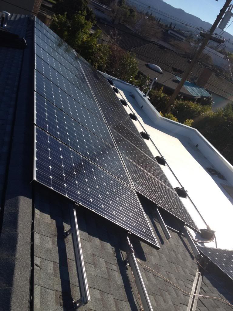
South bound azimuth is 165.5*, array Tilt @ 18.2* 12 panels 15 AMP over current protected.
West Bound azimuth is 255.5*, array tilt @ 18.2* 17 panels 20 AMP over current protected.
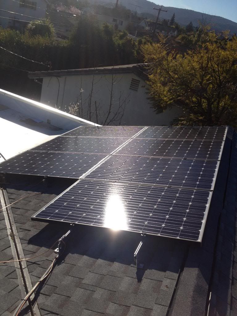
We engineered a flat portion of the roof angled at 9.5* to utilize white PTFE roofing to reflect additional solar radiation to roughly 90% of the west bound array and 60% of the south bound array 30% of the south bound unfortunately will have shading issues from a tree that the client did not want to cut down. The impact of that shading occurs for roughly 30% of south azimuth panels whihc will affect the PV watts daily average for those panels/micro inverters.
If any beginners or contractor have any Q&A's feel free to ask.
Please see attached pics, that I have so far, I will keep you all updated.
Kindest Regards
Thought I would include pics of my solar build from start to finish.
I consulted and designed this project for a client. The objective was to optimize a ROI by year 6 at the latest.
Client chose to invest into a TESLA S with charge station so we filed with PG&E to offset the price structure so that the bill remains in tier 1 to optimize that return, instead of being billed higher into tier 2 at peak hours of use.
Also assumed the average kWh consumption of the Tesla -S for daily commute driving would not exceed 15kWh within a 24 hour day range. The car alone will offset fossil fuel cost on the mile per gallon which helps to accelerate the return.
We've removed any appliance from the home that converts electricity to heat such as 240V cloths dryer, and electric stove range. All appliance units have been converted to gas, and for that reason client removed the 50 gallon water tank and replaced with (2) 9.5GPM tankless water heaters both exterior installations.
The system specs 29 canadian solar CS6P-260M, coupled with enphase M215 micro Inverter.
Both Client and I have high hopes for this system. I calculated the PVwatts predictions after DeRate @ 78%, 1% above the 77% default, the AC CEC should be roughly at 5.9kWh according to PV watts predictions. Optimal efficiency at 1000m2 the system can effectively/mechanically operate at 91% even after all conductor derates, however very doubtful that a phenomenon like that would probably only occur maybe 4 days out of the year.
We have high expectations after further reviewing harvest efficiency of micro inverter and that the incoming grid voltage for the inverters to sample is at a healthy 122.5V per pole. (244V single phase). I contacted enphase to get the maximum power output of the micro inverter. It was confirmed that the M215 can perform to a maximum power output of 226watts.
South bound azimuth is 165.5*, array Tilt @ 18.2* 12 panels 15 AMP over current protected.
West Bound azimuth is 255.5*, array tilt @ 18.2* 17 panels 20 AMP over current protected.
We engineered a flat portion of the roof angled at 9.5* to utilize white PTFE roofing to reflect additional solar radiation to roughly 90% of the west bound array and 60% of the south bound array 30% of the south bound unfortunately will have shading issues from a tree that the client did not want to cut down. The impact of that shading occurs for roughly 30% of south azimuth panels whihc will affect the PV watts daily average for those panels/micro inverters.
If any beginners or contractor have any Q&A's feel free to ask.
Please see attached pics, that I have so far, I will keep you all updated.
Kindest Regards


Comments
-
Re: My 7.5kWh micro Inverter (Build In Progress)
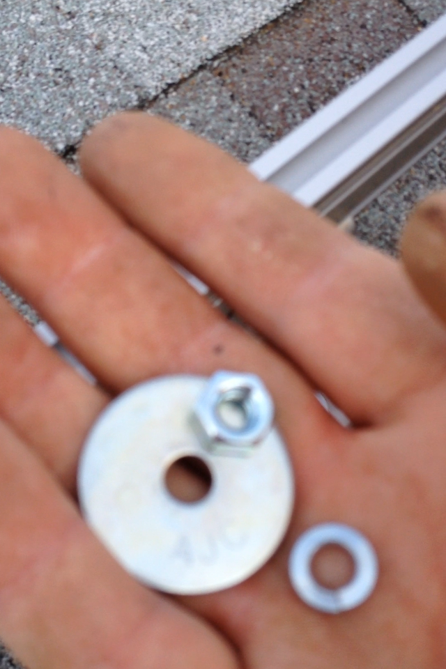
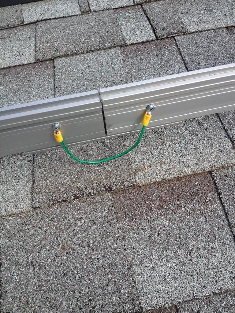
Additional racking and grounding pics!!!
Disconnects to be installed monday.
Panels and commissioning on wednesday!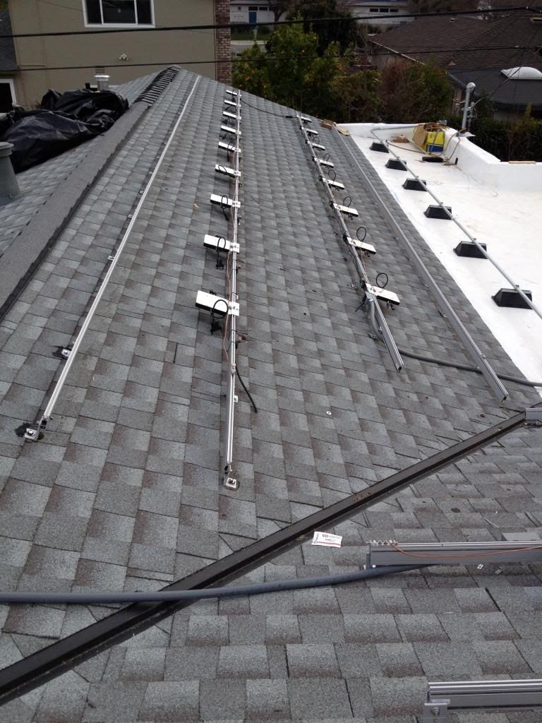
-
Re: My 7.5kWh micro Inverter (Build In Progress)
While you can save money ( 50-100% on racking ) with a L-Bracket's screwed down onto asphalt shingles it won't pass code here or considered acceptable attachment. Each roof penetration must have a flashing and the bracket attached to a Standoff. The cost of each penetration is $50- $70.
Attachment not found. -
Re: My 7.5kWh micro Inverter (Build In Progress)Blackcherry04 wrote: »While you can save money ( 50-100% on racking ) with a L-Bracket's screwed down onto asphalt shingles it won't pass code here or considered acceptable attachment. Each roof penetration must have a flashing and the bracket attached to a Standoff. The cost of each penetration is $50- $70.
Attachment not found.
That's not entirely true.
It has to be an engineered and approved method. Which in almost every jurisdiction I have been in California the method works. I also have an engineer that will sign off on the means and method every time if I have an issue with a jurisdiction.
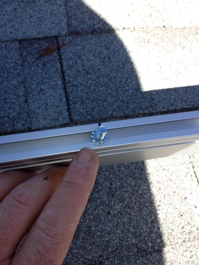
Mine is a 4 part means and method.
-Drill hole
-Fill hole with henry's 208(R) tar
-Apply butyl tape to the base of L feet
-Install Lag screw In/LBs~Ft/Lb's call out according to rack manufacturer.
This is the instruction and pic I send off to every AHJ.
Attachment not found.
I've installed solar myself for 6 years, consulted for 9 years, using this method, which I took from another firm that used this method minus the henry's 208R tar to fill the holes, when I was just a construction manager. This firm I worked for also did this means and methods on projects for out of state. Its an acceptable method as long as the shake roof is new, if its old it just crumbles apart, and who installs solar n a old shake roof????
The tar and butyl tape when compressed makes a liquid tight seal.
No leaks and will last, I use butyl tape for leak proof spill seals at a bio diesel refinery its good stuff.
I'm glad you caught what I did, means you are a meticulous person, alot of people wouldn't of caught that. -
Re: My 7.5kWh micro Inverter (Build In Progress)
I wasn't just nit picking, If it works for you and for them I'd go for it to. Here isn't California and every code is different as we see posted in here daily. Neat Install. -
Re: My 7.5kWh micro Inverter (Build In Progress)Blackcherry04 wrote: »I wasn't just nit picking, If it works for you and for them I'd go for it to. Here isn't California and every code is different as we see posted in here daily. Neat Install.
I know you weren't being nit picky those are the kinds of q&a's I like people to ask or state.
As far as install time and the savings on flashing and standoff its roughly a 16% savings between labor and material cost, for the racking/structural scope of work.
For foam composite and or steel roofs in the farm industry I use the same method however henry's 208R tar has to be spec changed/substituted to use NP1 or a polyurethane of "door and window" spec. -
Re: My 7.5kWh micro Inverter (Build In Progress)
I see you have multiple horizons on the install. Did you calculate each array separately when making you output claims? -
Re: My 7.5kWh micro Inverter (Build In Progress)
Yes I did.
Micro inverter calcs are a little tricky for the NET metering since everything calculated independently as units per inverter.
The unit value per inverter annualized comes out to 208 watt hours CEC AC or (.208kWh CEC AC), which I believe is a reasonable assessment.
So with PV watts I calculated for a south azimuth array, and a west azimuth array.
Then from there a division process divided by 12 for south azimuth, and another division process divided by 17.
For the south bound I left all the numbers the same at the higher value, my client always has the option to chop his tree down.;) -
Re: My 7.5kWh micro Inverter (Build In Progress)
Thank you very much for posting this.
I'm getting ready to install a very similar system also with Enphase in Kansas City.
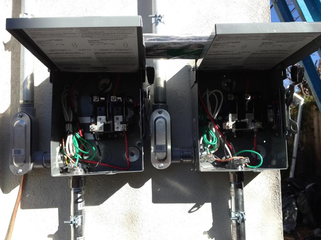
If you don't mind I have a couple of questions on the wiring.
1. What is the purpose of the flex conduit? I was planning to install my J-Box on the racking but your j-box appears to be set some ways away.
2. How many strings do you have. It looks like the discontinuous rows are being wired together or are they each a separate string.
3. Is that THWN 10 Ga or 12 Ga stranded. I’m getting all kinds of conflicting advice.
4. I plan to use PVC instead of EMT. Is there some reason you prefer EMT.
Sorry lots of questions. -
Re: My 7.5kWh micro Inverter (Build In Progress)
My responses in red for clarity in communication.Thank you very much for posting this.
I'm getting ready to install a very similar system also with Enphase in Kansas City.
If you don't mind I have a couple of questions on the wiring.
1. What is the purpose of the flex conduit? I was planning to install my J-Box on the racking but your j-box appears to be set some ways away.
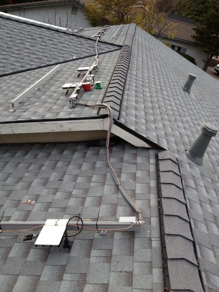
It was engineered that way for a few reasons.
1) I could of used enagage extension trunk cable however the trunk cable would of been exposed to the sun, so hypothetically on a 80~90* ambient temperature summer day in full sun, black trunk cable will absorb that solar radiant light and the cable can reach tempratures 20* higher than that ambient temperature so it can increase voltage drop just in that 6' exposed run.
2) I already purchased 200' of 10AWG THHN for the south and west bound home runs( the ground THHN still remains 12AWG) as that is how the system is calculated. 10AWG was used to reduce voltage drop for the 80' homerun, not accounting for the sub array gaps to the south bound system.
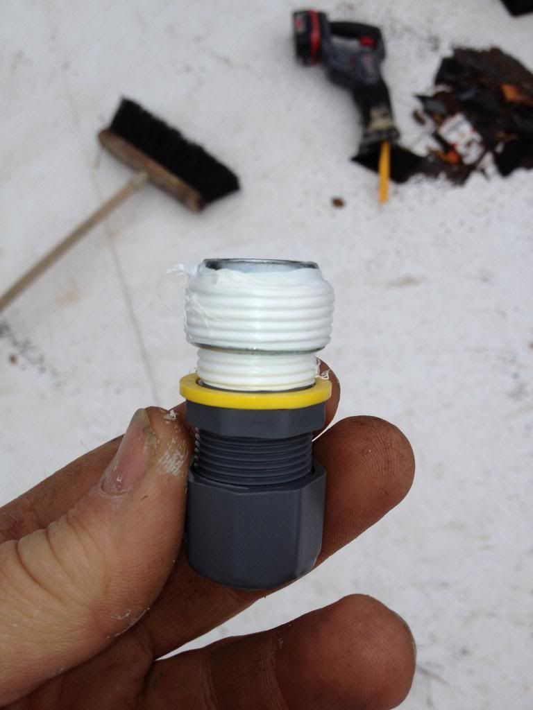
3) 3/4" shielded liquid tight(flex) was as well used because of the pack and fill of conduit sizing, and to help reduce thermal inefficiency.
2. How many strings do you have. It looks like the discontinuous rows are being wired together or are they each a separate string.
3 sub arrays make up the south bound portion, the west bound is one solid array. The south bound has a total of 12 west bound is at its maximum of 17. South bound is overcurrent protected @ 15amps, west bound is over current protected @ 20amps.
3. Is that THWN 10 Ga or 12 Ga stranded. I’m getting all kinds of conflicting advice.
Enphase trunk cable comes in 12AWG THHN~THWN rating, the 10AWG I purchased for between sub arrays and home run is THHN. The ground conductor for homerun and sub arrays is 12AWG THHN.
4. I plan to use PVC instead of EMT. Is there some reason you prefer EMT.
I use IMC "Inter Mediate Conduit" with rigid couplers. I do not use PVC or EMT as a contractor that has to warranty for 10 years. EMT fails with compression couplers, in the hot sun EMT expands and the compression fitting over time separate. According to much regulation with solar, PVC is not recommended in most circumstance (unless underground connections in either dB120 or sch40), most local jurisdictions in california do not allow it. I IMC everything, unless if its traffic rated which then I step up to RMC (Rigid Metal Conduit). Long term IMC is the way to go if not commercial or traffic rated, the systems that last the full 25 year warranty are the ones built with threaded fittings, the cost savings over the life time of the solar system, between EMT and IMC is enormous. Just to spend the little extra time and funds to invest into IMC will reduce future costs in repairs from either depreciation or liable damage. For me its a must do, the end result is my clients see the extra effort I put in for the .987 cents per watt, and don't mind investing into the better material.
Sorry lots of questions.
No problem, its still a learning curve for me.")
-
Re: My 7.5kWh micro Inverter (Build In Progress)
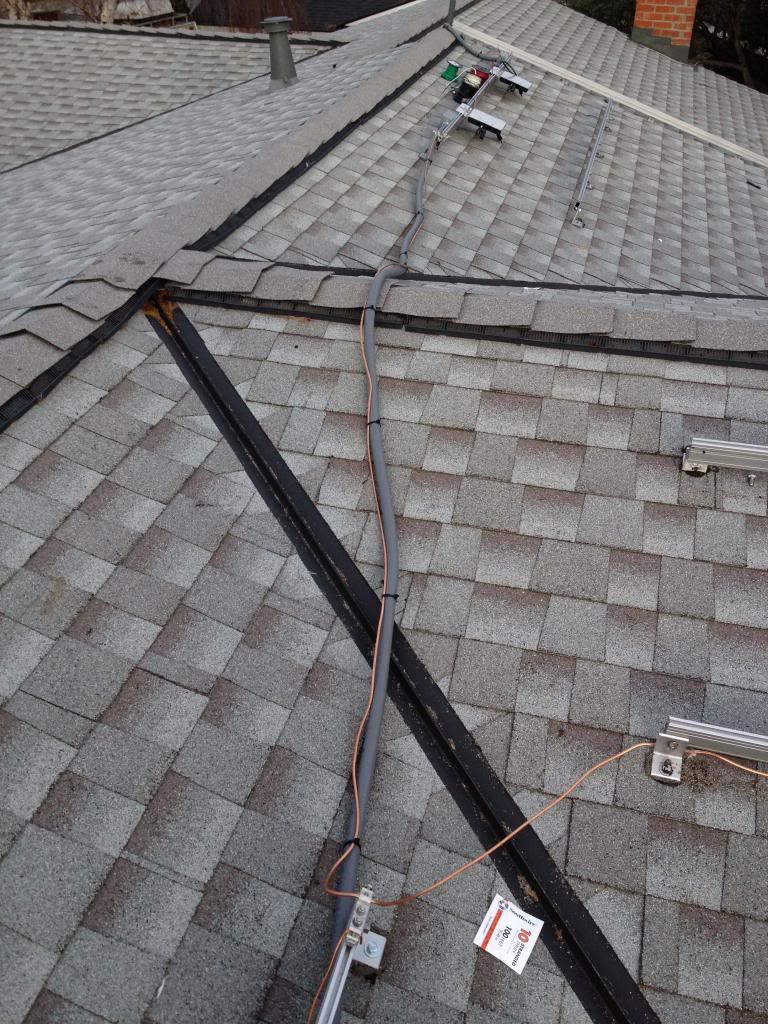
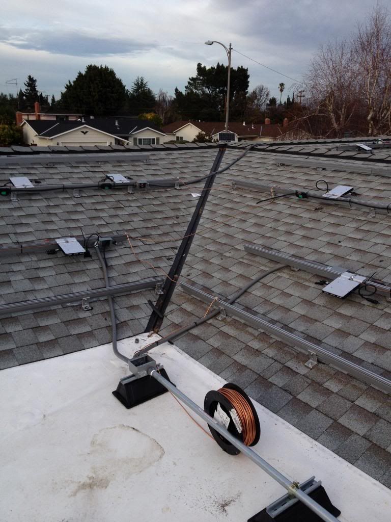
More pics of grounding and disconnect installation.
In the process of commissioning at the moment so I am short on time. Will get back to every one this sunday, when I have some time to relax.
Enjoy!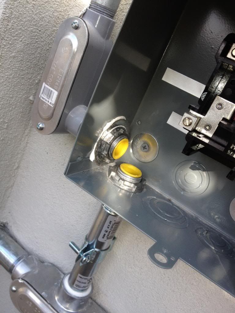
-
Re: My 7.5kWh micro Inverter (Build In Progress)
Commissioning the system for the next 48hours. Since I worked by myself installing 29 panels, the liability of VOC/ISC testing was too risky working alone on a 18.2* pitched roof so I am trusting the enphase enlighten system to weed out the bad apples. I will take the base average of watts divide by 29 panels, any wattage of panel that falls below 5% if any do I will have to disconnect and trouble shoot. If you see the jagged curve from 9am, until 1:12pm that was me installing each panel 1 by 1. I will be monitoring tomorrow, told client its O.K to charge his car for now, but to shut the system down at disconnects at 5pm. Will incorporate tomorrows results.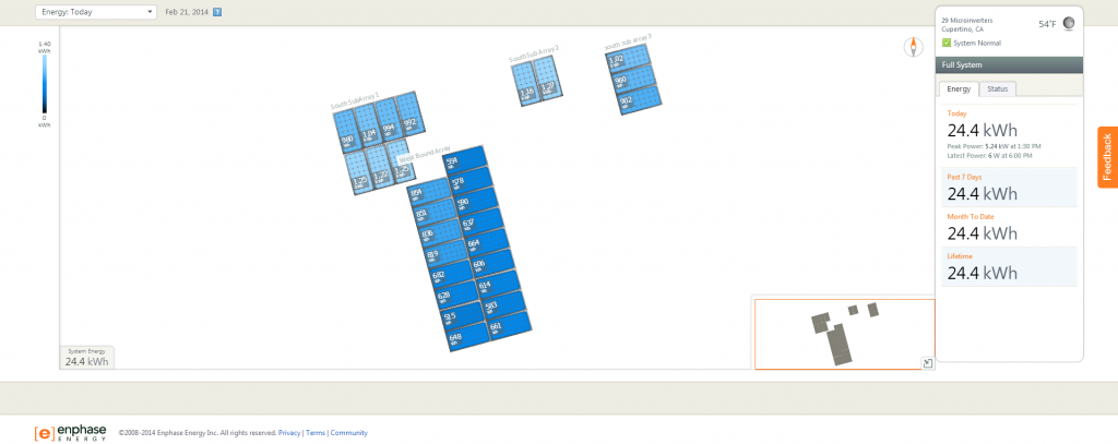
-
Re: My 7.5kWh micro Inverter (Build In Progress)
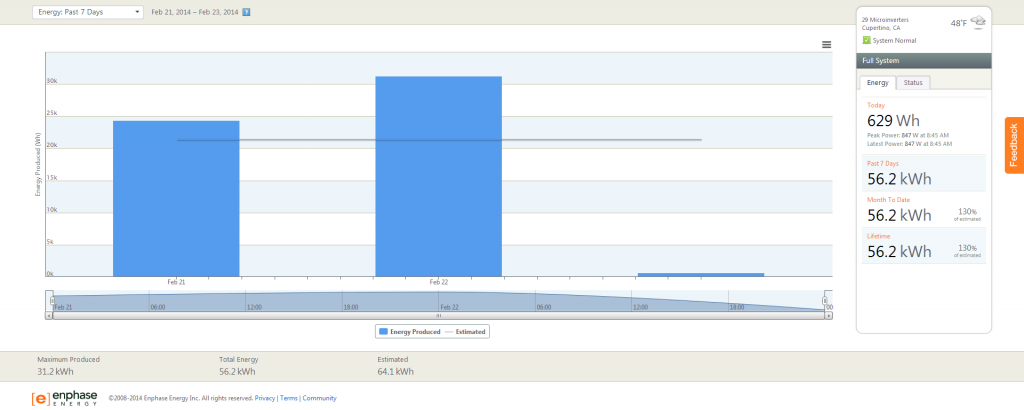
Results from commissioning yesterday gave alot of data.
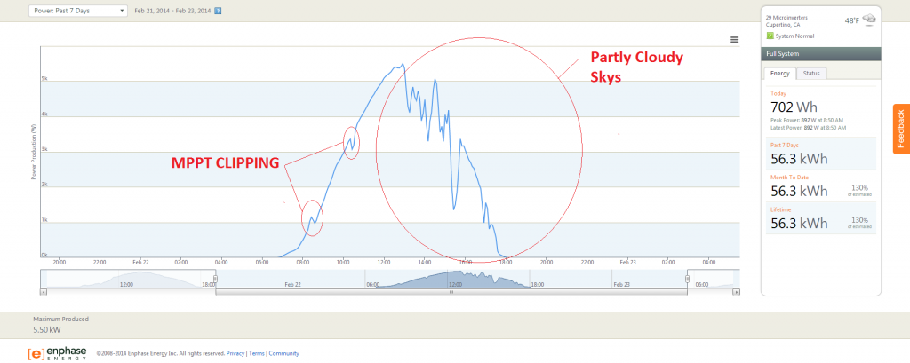
There were partly cloudy sky's from 1:30 until standby which occurs roughly @ 6pm.
Collecting the data for the total days range there will be 2 panels that I need to disconnect on monday and work on VOC/ISC as I believe they fall below the 5% power tolerance of the panels, either that theory, or the inverters are not operating correctly within the MPPT range.
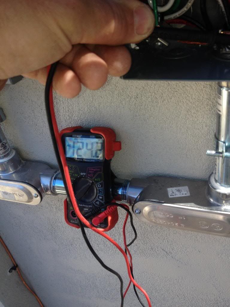
This system is a very powerful system. Grid voltage recorded prior to solar install was 122.5V per pole, grid voltage after the installation of solar was 124.1V per pole.
Enphase inverters do all they can to operate outside the 190~270watt MPPT range (this is one of the plethora of reasons why micro inverter is far superior to grid tie string inverters), as you can see from the snap shots the system begins operation @ 1 watt. PVwatts only accounts for efficiency range of operations as if any other operation is standby. There is apparently whats called MPPT "clipping" that once the inverter does find that range of operation it has to ramp up and up convert amps to volts to match grid voltage.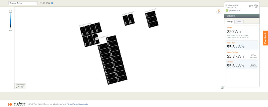
-
Re: My 7.5kWh micro Inverter (Build In Progress)
Does white PTFE composite roofing improve system performance?
Unlike Solyndra that never verified proof of this, I would have to say yes it does...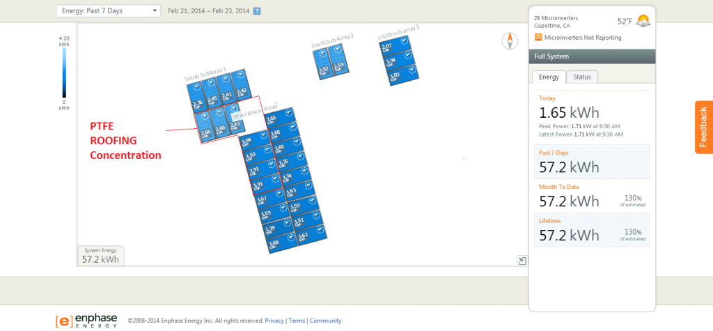
-
Re: My 7.5kWh micro Inverter (Build In Progress)
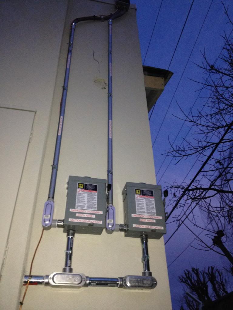
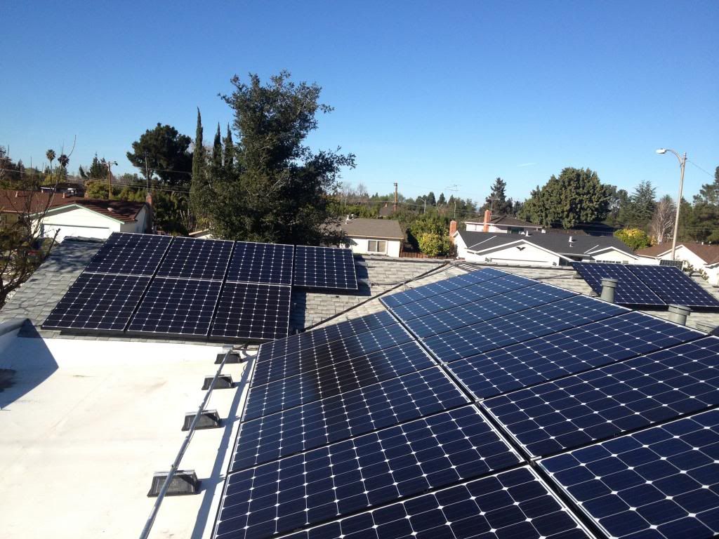
Here is the final product. Lots of blood and sweat on this one. Was stuck getting the project done myself. Client was impressed with every aspect of my means and methods of my installation. I won the bid for this job VS 2 other competitive bids not only because of price, but because I was a construction manager for a few large firms, was a QA coordinator, and handle patent R&D for new products in development or under development, my client believed he would get a better performing and quality result. To say the least he was thoroughly impressed.
The only aspect both I and the client were upset about was that we were promised (IG) micro inverters from distribution and that wasn't what we received and had to spend the extra money on 8AWG bare solid copper for grounding.
Hope you all enjoyed viewing. There will be updates in the future as this project will be the home base for updating and improving my PV watts estimates for the latitude and longitude of this area.
Any Q&A's feel free to ask.
Cheers!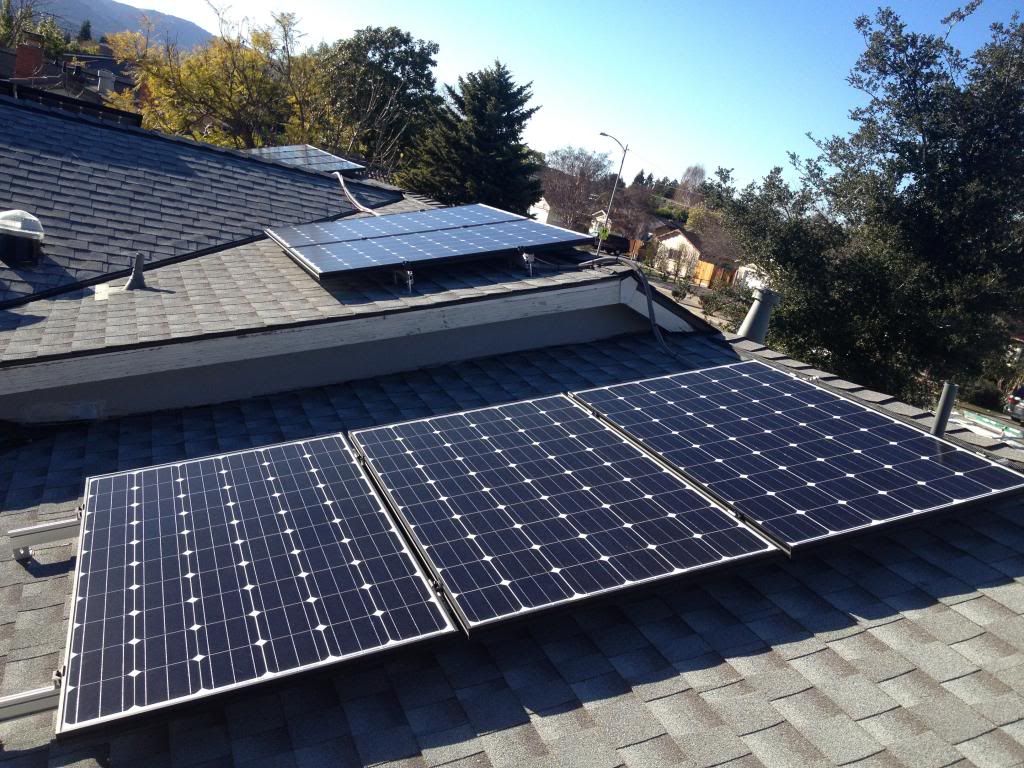
-
Re: My 7.5kWh micro Inverter (Build In Progress)
Hi,
If you could answer one more question I'd appreciate it.
I noticed in your pictures that some panels have access from the ridge and some panels access from the eave. If you had to make a choice which is better. Esp. without a flat roof portion. Hope that is not a confusing question. The reason I ask is that I have to make this choice on my install and am conflicted. -
Re: My 7.5kWh micro Inverter (Build In Progress)Hi,
If you could answer one more question I'd appreciate it.
I noticed in your pictures that some panels have access from the ridge and some panels access from the eave. If you had to make a choice which is better. Esp. without a flat roof portion. Hope that is not a confusing question. The reason I ask is that I have to make this choice on my install and am conflicted.
My permits for this project processed last year prior to the new set back regulations.
New set back regulations is to have 3' on all sides if you pull permits for this year. Its so the NFPA, and the local fire department jurisdictions have access for draft opportunity which are to be 3'X3', with isle pathways to be minimum 3' for that access and draft opportunity.
Chances are it will be hard for you to design around the new set back regulations. Just saying because it was going to be difficult for myself if I didn't process the plan set last year. My client would of lost 1560 kWh of panels. I wasn't going to let that happen, and when I promise a desired optimum power output, I had to be my own advocate to make it happen. -
Re: My 7.5kWh micro Inverter (Build In Progress)
Theo1000,
Here is the explination as to why you can't do what I did...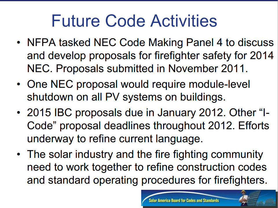
this is the basic design layout.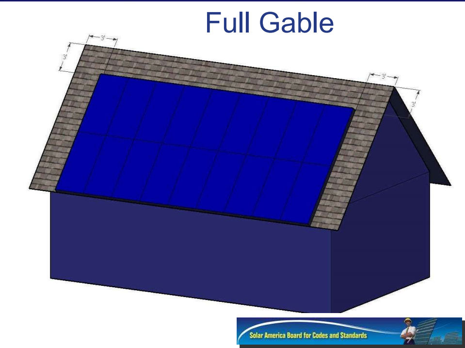
Everything you need to know can be found here.
http://www.nfpa.org/~/media/Files/proceedings/PhotoVoltaicBrooks.pdf -
Re: My 7.5kWh micro Inverter (Build In Progress)
You know even at my age I can swing an axe through a solar panel and/or its mounts and reduce it to insignificant rubble. In fact I can do that much faster than I could chop a hole through a roof.
More unnecessary regulations invented by the uninformed.
Biggest problem with "whole panel" roofing is that it is a pain in the anatomy to construct in the first place and even worse to work on later (no easy access to mounts and wiring connections). -
Re: My 7.5kWh micro Inverter (Build In Progress)
Most roofs (including my own) have a north facing roof flat that is completely panel free--And in my case, faces the street for access.
If venting is such a beneficent (and the few times I have discussed with fire fighters, it is), then make the darn code require pop-up smoke/vent hatches/cupula and call it a day. It would save time and walking on roofs during poor weather/visibility.
I agree with Marc, it seems it would be a lot easier to put an ax through a couple panels vs trying to cut through all of the different roofing materials/systems out there.
-BillNear San Francisco California: 3.5kWatt Grid Tied Solar power system+small backup genset -
Re: My 7.5kWh micro Inverter (Build In Progress)I agree with Marc, it seems it would be a lot easier to put an ax through a couple panels vs trying to cut through all of the different roofing materials/systems out there.
Any chance of putting that ax into 400 volts DC? --vtMaps4 X 235watt Samsung, Midnite ePanel, Outback VFX3524 FM60 & mate, 4 Interstate L16, trimetric, Honda eu2000i -
Re: My 7.5kWh micro Inverter (Build In Progress)Any chance of putting that ax into 400 volts DC? --vtMaps
No worries. A few sparks and it's over. The building is on fire anyway, and the axe has a fibreglass handle. -
Re: My 7.5kWh micro Inverter (Build In Progress)
Thank you for the detailed reply. Sounds like yet another regulation complication. Fortunately I have already pulled my permit from a less 'experienced' midwest jurisdiction. No access requirements were specified.
In any case I'm sorting my panels into double columns with access aisles all the way to the ridge. The only place I have an issue is at the Eave or Ridge where I have to choose between providing a 3' access aisle at the Eave or the ridge. Maybe there is no set answer. Just collecting opinions from experienced folks. -
Re: My 7.5kWh micro Inverter (Build In Progress)
In any case I'm sorting my panels into double columns with access aisles all the way to the ridge. The only place I have an issue is at the Eave or Ridge where I have to choose between providing a 3' access aisle at the Eave or the ridge. Maybe there is no set answer. Just collecting opinions from experienced folks.
Fire fighters prefer the ridge for access, the highest peak ridge allows for the best drafting. My cousin is a firefighter for sacramento fire department.
I agree with caribocoot that it is an uninformed group of bureaucrats that make it difficult with all this regulation but from the firefighters end, you have to consider how jellybrain a firefighter gets after working split shifts and on call for 24hours. My cousin tells me that on call, there is literally no sleep. It has to suck for that group of people and you have to think that some of them throw the thought process out the window and what its going to take to spray some water on the situation. -
Re: My 7.5kWh micro Inverter (Build In Progress)SolarPowered wrote: »Both Client and I have high hopes for this system. I calculated the PVwatts predictions after DeRate @ 78%, 1% above the 77% default, the AC CEC should be roughly at 5.9kWh according to PV watts predictions. Optimal efficiency at 1000m2 the system can effectively/mechanically operate at 91% even after all conductor derates, however very doubtful that a phenomenon like that would probably only occur maybe 4 days out of the year.
Correction, Now that I am an official enphase installer enphase contacted me so that my PV-Watts De-Rates can be adjusted much more accurately.
The calculator should be set for 86.5%.
Attachment not found.
Here is the whole PDF article.
http://enphase.com/global/files/Enphase_PVWatts_Derate.pdf -
Re: My 7.5kWh micro Inverter (Build In Progress)SolarPowered wrote: »
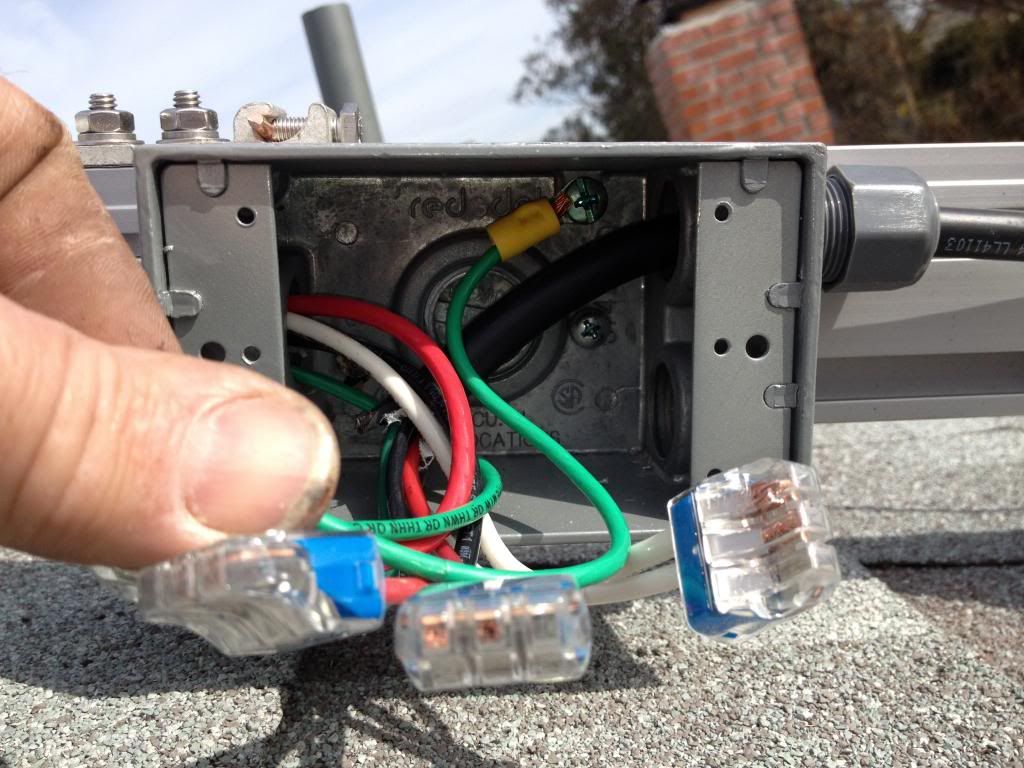
I have another question on this image if you don’t mind.
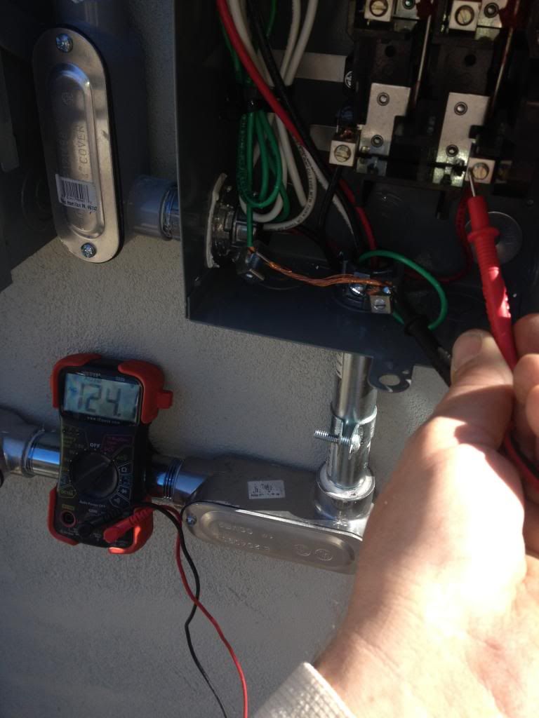
It looks like the Green neutral is being grounded to the box. Is this what is required by the jurisdiction. From what I can discern the custom here is to run the Green neutral to the neutral bar seperately and run a separate bare copper as grounding to the junction boxes and equipment. Is there some reason the Bare copper grounds the equipment but not the box/conduits?
Thanx very much for any response. -
Re: My 7.5kWh micro Inverter (Build In Progress)I have another question on this image if you don’t mind.
It looks like the Green neutral is being grounded to the box. Is this what is required by the jurisdiction. From what I can discern the custom here is to run the Green neutral to the neutral bar seperately and run a separate bare copper as grounding to the junction boxes and equipment. Is there some reason the Bare copper grounds the equipment but not the box/conduits?
Thanx very much for any response.
In standard colour-coding of wiring green is ground, white is neutral. -
Re: My 7.5kWh micro Inverter (Build In Progress)I have another question on this image if you don’t mind.
It looks like the Green neutral is being grounded to the box. Is this what is required by the jurisdiction. From what I can discern the custom here is to run the Green neutral to the neutral bar seperately and run a separate bare copper as grounding to the junction boxes and equipment. Is there some reason the Bare copper grounds the equipment but not the box/conduits?
Thanx very much for any response.
its code and also a requirement in enphases instruction manual.
lets say hypothetically it wasn't solar, let's just say that box would be a serviceable GFCI "hypothetically". Any exterior metallic box should be grounded to GEC. Many people confuse this. Ground is ground whether GEC or not, point is for safety concerns you can never be to safe. Most inspectors will fail you if you don't ground system ground to boxes. Remember it's all alternating current you are dealing with, and it's not a DC side grounded system where the inverter will determine ground fault detection if it were negative or positive grounded to GEC.
enphase inverters are awesome in the fact that if a solar panel is negative or positive grounded, the patent IG system is compatible for either type of solar panel(I.E) solar worlds are positive grounded, Canadian solars are negative grounded. -
Re: My 7.5kWh micro Inverter (Build In Progress)
Thanks Caribocoot, I mess up there. Learning as I go….
OK. So the Green is Ground and the Bare copper is also ground but they should not meet until the grounding bar. The White is neutral.
So I should not join the Green to the Bare copper anywhere earlier right?
I was trying to ground the bare copper to the j-box and then run the bare copper within the conduit to the neutral bar. Cleaner look.
So can I still run the copper through the conduit ? just not connect it to the green ground? -
Re: My 7.5kWh micro Inverter (Build In Progress)
Bare copper ground tends to be solid wire. It's not being used here because the cable going in and out of the box is flexible, so it includes multi-strand green insulated wire for grounding. There is no problem with tying one ground wire to another anywhere within the system, so long as it doesn't 'loop back'.
The thing that caught my attention was your use of "green neutral"; I had visions of someone connecting neutral to ground in more than one location, which is to be avoided. -
Re: My 7.5kWh micro Inverter (Build In Progress)
This is why I’m not an electrician. :-) There are a fewer older homes around here where the neutral is the ground. Not sure if it is up to code. You can usually tell by the winking lights.
So the bare copper does not have to run all the way to ground?
I run a loop connecting all the racking, panels, inverter.
And then the green ground from the inverter grounds the box/conduit/connections (said inverter connects to the bare copper anyway).
I would prefer this as then I don't have to deal with the bare copper inside the conduit etc.


Categories
- All Categories
- 234 Forum & Website
- 142 Solar Forum News and Announcements
- 1.4K Solar News, Reviews, & Product Announcements
- 200 Solar Information links & sources, event announcements
- 901 Solar Product Reviews & Opinions
- 256 Solar Skeptics, Hype, & Scams Corner
- 22.5K Solar Electric Power, Wind Power & Balance of System
- 3.5K General Solar Power Topics
- 6.7K Solar Beginners Corner
- 1K PV Installers Forum - NEC, Wiring, Installation
- 2.1K Advanced Solar Electric Technical Forum
- 5.6K Off Grid Solar & Battery Systems
- 430 Caravan, Recreational Vehicle, and Marine Power Systems
- 1.1K Grid Tie and Grid Interactive Systems
- 656 Solar Water Pumping
- 817 Wind Power Generation
- 624 Energy Use & Conservation
- 624 Discussion Forums/Café
- 316 In the Weeds--Member's Choice
- 75 Construction
- 125 New Battery Technologies
- 108 Old Battery Tech Discussions
- 3.8K Solar News - Automatic Feed
- 3.8K Solar Energy News RSS Feed