Another Grounding Question

Fatawan
Solar Expert Posts: 71 ✭✭✭
I am installing a 48 panel array, ground mounted, with Enphase inverters. This will be located 25-65' from the meter and existing ground rod. Mount will be made of galvanized steel pipe and aluminum extrusion. Will I need a ground rod at the array, and run a single copper ground wire through the Enphase modules, as well as a separate ground wire to each panel and to the ground rod? What other options might I have? I have to speak with the inspector before starting, so I would like to be ready.
Comments
-
Re: Another Grounding Question
actually by wiles' crazy rules at the nec you need to run the ground lead into your home along with the pv leads and run backwards through your equipment to the home breaker box and then to the ground rod. talk to your inspector and complain to him that for a lightning strike, or even the emp of a nearby strike, a ground rod is needed at the pvs and should be tied underground to the main utility ground rod, and not backwards through the house, with at least a #6 bare solid copper wire buried about a foot or more to prevent accidental breakage. as wiles would have you do it, he would allow separate ground rods, but that sets up dissimilar grounds and dangerous ground loops and would still allow the lightning a direct entrance to the home. -
Re: Another Grounding Question
Agreed, I would never run the wiring from another rod directly into the breaker box or other equipment. All rods should have common tie point on the utility ground and a single bond from that common tie point into the house. The surge protector on the DC wiring from the PV array should also be connected to this common tie point.
I just looked up his diagram on PV grounding. The PV ground rod needs a direct bond to the other rods and not loop thru the disconnect and inverter. You don't want the current from GPR looping into the inverter.
http://el-mag.biofutur.org/2010/02/pv-grounding-continued/Ground-mounted PV arrays should have an additional grounding electrode at the array location. It is connected to the equipment-grounding system for the module frames and the array structure. Not only is this a code requirement (due to the location of the PV array away from the inverter), it will enhance the ability of the system to deal with lightning surges. This supplementary DC grounding electrode does not have to be bonded directly to the main DC grounding electrode. It is connected indirectly to the main DC grounding electrode through the equipment-grounding conductors. Grounding is a complex subject, and the information here covers only the high points. For more information, see the suggested references in Access.
I can't see his reason for this. -
Re: Another Grounding Question
So in my case, using Enphase microinverters, the inverters could be grounded to the same rod as the panels, which in turn should be bonded to the ground rod located near the ComEd meter? -
Re: Another Grounding Question
fatawan,
i strongly urge you to consult either your inspector or a good electrician on this as grounds can be tricky. i am also unfamiliar with enphase particulars, but did dig this up,
http://www.builditsolar.com/Projects/PV/EnphasePV/Wiring.htm
now in that example they have a distribution panel outside and it is directly grounded there outside. most of us have a distribution panel inside the home and therein lies the problem of bringing lightning and emp into the home before it is then routed to the outside utility ground.
thank you nsaspook for digging up that diagram as it does illustrate how the nec dictates things to be grounded. although the ground rod is there for the pvs the potentials will still travel towards the equipment and other ground rod too via that ground wire going into the home. a difference exists with enphase in that the inverters are outside instead of inside, but that ground wire will still go to the home's interior even with the enphase system. what i like is to have the pvs grounded to a rod as per the diagram, but the inverter grounds will also need to go to the exterior ground rod (and here is where i differ with the nec) with no ground wire running side by side with the hot wires to an interior distribution box. instead the ground lead for that should go directly to the outside ground rod. the wire will also go from that ground rod and then to the distribution panel. see the difference?
it seems complicated and it can be difficult to explain, but the idea is to prevent lightning or the emp going into the home needlessly through that ground wire. it should go to ground rod outside. i should reiterate that 2 separate ground rods tied with wire above ground is not properly grounded and a difference of potential (ground loops) will develop between the 2 ground rods. to avoid the potential ground loops, those rods need tied together underground rather than in the air and no ground wire should be allowed to enter a home needlessly.
now the way i state it should go violates the nec and the nec is violating a properly grounded and protected system from being realized by bringing the ground wire into the home and introducing ground loops by more than 1 ground rod not being correctly intertied. you need an inspector's approval to overide the nec and go with my better method. -
Re: Another Grounding QuestionSo in my case, using Enphase microinverters, the inverters could be grounded to the same rod as the panels, which in turn should be bonded to the ground rod located near the ComEd meter?
Well... according to the Enphase manual:
http://docs.google.com/viewer?a=v&q=cache:oVK8hXSsvFwJ:www.enphaseenergy.com/downloads/M200_M175_User_Manual_20081110.pdf+wiring+enphase&hl=en&gl=us&pid=bl&srcid=ADGEEShfhyOewE3pLSYPr92aEb77PwYhZVwLTyQAgnypU5R7G1-JHnEc2zsGvvyjF5EZyWQQlbRwD8m79g_7rOU9H5H_50t-fdLKo40i6lekN0Tt5IzPBTjCTZud4TcfTfmEVQEuAOeB&sig=AHIEtbTNbDrHLNIrJGDpTms49V-0c_kXBA
The external chassis ground lug on the Enphase inverter is for a GEC. The manual states:
"Step 4 – Grounding the System
Each Enphase Micro-inverter comes with a ground clip that can accommodate a 6-10 AWG conductor.
a. Route a continuous GEC through each of the Micro-inverters and AC
branch circuit junction box to the NEC approved AC grounding electrode.
NOTE: The AC output neutral is not bonded to ground inside the Micro-
inverter."
In other words, an unbroken wire all the way back to the main electrical panel ground rod.
However, the Enphase is in a gray area in the code because A) is has no AC EGC (equipment grounding conductor) connection, and") it does have a DC GEC (grounding electrode conductor) connection. So for some doofy reason, it is permitted to combine both into a single wire. Wiles addresses that here:
it does have a DC GEC (grounding electrode conductor) connection. So for some doofy reason, it is permitted to combine both into a single wire. Wiles addresses that here:
http://docs.google.com/viewer?a=v&q=cache:yvjGTkEWTU8J:www.nmsu.edu/~tdi/Photovoltaics/Codes-Stds/WIRING%2520ENPHASE%2520MICROINVERTERS-12.pdf+enphase+grounding&hl=en&gl=us&pid=bl&srcid=ADGEESjdP4f_Fxus1hcjfbnxKfg8uPRKX4n_BCIUfoi8a8r2q2rWLaK8MSsdW_tk3LJpcbdRLxoS0dBQmk455_W0wxIuGr9uT2cX9ILUNP8xXoj-8Ij32K6OLMMXFUtq4SzK5UvlfMcX&sig=AHIEtbQXZIA7Guq6U8MguTAyXjutMjIKMw
He describes how it can be done, starting at Paragraph 17. -
Re: Another Grounding QuestionI can't see his reason for this.
Because the array ground rod is supplemental. It's not even required unless the array is separate from the building.
The connection from the inverter though the disconnect to the supplemental ground rod is really just to serve as an EGC, so it can be routed as would any other EGC and isn't required to be continuous or unbroken as would a GEC.
That's how it looks to me anyway. -
Re: Another Grounding QuestionBecause the array ground rod is supplemental. It's not even required unless the array is separate from the building.
The connection from the inverter though the disconnect to the supplemental ground rod is really just to serve as an EGC, so it can be routed as would any other EGC and isn't required to be continuous or unbroken as would a GEC.
That's how it looks to me anyway.
Bonding in this case in not for simple electrical safety but for lighting surge protection what the NEC seems to have no idea about. Think of the PV array like a TV cable system to your house, it's grounded on the cable company supply side but the proper way to ground it at your house is on the utility ground before it comes in the house. For proper surge protection ANY external cable ground should be bonded at the GEC and then EGC wires can connect equipment. -
Re: Another Grounding QuestionFor proper surge protection ANY external cable ground should be bonded at the GEC and then EGC wires can connect equipment.
And is that not exactly what is happening in that drawing? The ground wire from the inverter to the array IS bonded to a GEC.
It's just not bonded to the AC GEC except though the EGC. -
Re: Another Grounding QuestionAnd is that not exactly what is happening in that drawing? The ground wire from the inverter to the array IS bonded to a GEC.
It's just not bonded to the AC GEC except though the EGC.
This is now the only current path for a surge that originates from the PV array to travel. Because the EGC wiring may be long, have sharp bends and be close to sensitive equipment your risk of damaged equipment increases vice a direct connection to the GEC that has different requirements due to lightning protection.
NEC 2011 seems to have seen the light on this.9. 250.121 Use of Equipment Grounding Conductors
A new section was added to prohibit the use of the equipment grounding conductor as a grounding electrode conductor.
250.121 Use of Equipment Grounding Conductors. An equipment grounding conductor isn’t permitted to be used as a grounding electrode conductor.
Analysis: The grounding electrode conductor (GEC) is intended to help direct lightning-induced energy to the earth, while an equipment grounding conductor (EGC) is intended to provide a low-impedance ground-fault current path to the source to operate overcurrent devices in the event of a ground fault. The requirements for sizing are also different. An EGC is sized in accordance with 250.122, while a GEC is sized using 250.66. Because these conductors have different rules, different sizing requirements, and different installation requirements, this section was added to clarify that one conductor can’t fill the roles of both an EGC and a GEC. -
Re: Another Grounding QuestionThis is now the only current path for a surge that originates from the PV array to travel.
Only path? Do you mean only path other than the array grounding electrode and/or the DC wires?An equipment grounding conductor isn’t permitted to be used as a grounding electrode conductor.
Right. And in that drawing, the ground wire in question is *not* being used as a GEC. It's being used as an EGC. The inverter is already directly tied to its own GEC, as is the array.
The extra wire is just to complete the EGC system by tying the inverter and disconnect chassis to the PV chassis. It's not there to serve as a bond between the electrodes. -
Re: Another Grounding QuestionOnly path? Do you mean only path other than the array grounding electrode and/or the DC wires?
Right. And in that drawing, the ground wire in question is *not* being used as a GEC. It's being used as an EGC. The inverter is already directly tied to its own GEC, as is the array.
The extra wire is just to complete the EGC system by tying the inverter and disconnect chassis to the PV chassis. It's not there to serve as a bond between the electrodes.
You are correct in a electrical fault protection sense but in a communicaions or data center that would never fly for proper grounding for lighting protection. Just saying it's a EGC connection does not stop the fact that if a near strike causes a rise in ground potential between the two grounding systems current will flow on that wire just like a surge on a TV coax cable from a pole blocks away. My point is you need both an electrical safety ground EGC and a lightning surge ground GEC just like you would need on sat dish on a pole near your house. -
Re: Another Grounding Question
I will speak with Mr. Wiles in the morning. I called him today and left a message, but missed his return call. He'll have the latest and greatest no doubt.
My county inspectors were of no help. They simply stated that I should follow manufacturers directions. They have never done a PV install before. I'll be the pioneer, with the arrows in my back. By the way, they base everything off of 2003 NEC guidelines...oh boy. -
Re: Another Grounding QuestionWell... according to the Enphase manual:
http://docs.google.com/viewer?a=v&q=cache:oVK8hXSsvFwJ:www.enphaseenergy.com/downloads/M200_M175_User_Manual_20081110.pdf+wiring+enphase&hl=en&gl=us&pid=bl&srcid=ADGEEShfhyOewE3pLSYPr92aEb77PwYhZVwLTyQAgnypU5R7G1-JHnEc2zsGvvyjF5EZyWQQlbRwD8m79g_7rOU9H5H_50t-fdLKo40i6lekN0Tt5IzPBTjCTZud4TcfTfmEVQEuAOeB&sig=AHIEtbTNbDrHLNIrJGDpTms49V-0c_kXBA
The external chassis ground lug on the Enphase inverter is for a GEC. The manual states:
"Step 4 – Grounding the System
Each Enphase Micro-inverter comes with a ground clip that can accommodate a 6-10 AWG conductor.
a. Route a continuous GEC through each of the Micro-inverters and AC
branch circuit junction box to the NEC approved AC grounding electrode.
NOTE: The AC output neutral is not bonded to ground inside the Micro-
inverter."
In other words, an unbroken wire all the way back to the main electrical panel ground rod.
However, the Enphase is in a gray area in the code because A) is has no AC EGC (equipment grounding conductor) connection, and it does have a DC GEC (grounding electrode conductor) connection. So for some doofy reason, it is permitted to combine both into a single wire. Wiles addresses that here:
http://docs.google.com/viewer?a=v&q=cache:yvjGTkEWTU8J:www.nmsu.edu/~tdi/Photovoltaics/Codes-Stds/WIRING%2520ENPHASE%2520MICROINVERTERS-12.pdf+enphase+grounding&hl=en&gl=us&pid=bl&srcid=ADGEESjdP4f_Fxus1hcjfbnxKfg8uPRKX4n_BCIUfoi8a8r2q2rWLaK8MSsdW_tk3LJpcbdRLxoS0dBQmk455_W0wxIuGr9uT2cX9ILUNP8xXoj-8Ij32K6OLMMXFUtq4SzK5UvlfMcX&sig=AHIEtbQXZIA7Guq6U8MguTAyXjutMjIKMw
He describes how it can be done, starting at Paragraph 17.
Thanks for the link--I'll read some more(though it's 2008, and things seem to change every year, at least.) -
Re: Another Grounding Question
from what i recall mr. wiles indicated the connection of a ground rod for the pvs is optional in all cases as he views it as grounded via through the dwelling to main entrance ground and rod. i wrote to him long ago on the subject of pv grounding and how a ground wire and rod should be required to be there for the pvs, but with an underground connection from a pv ground rod to the 1 main ground rod if not in the vicinity of the main entrance ground rod and not to enter the dwelling with the pv leads. his answer was a separate ground rod unbonded to the main ground rod and still required the unnecessary entry of the ground wire into the dwelling bringing with it emp and possibly lightning. this protects nothing as wiles has it and actually endangers equipment and people. he really does not have a handle on this or know what he is doing in this case. there should only be 1 ground and at no time should a ground lead be made to enter a dwelling needlessly in its quest to reach a ground rod that is already outside. duh!!
as i see nsaspook's drawing, instead of the ground wire going with the pv + and - leads into the house and then connect to ground leads in the home to reach the main entrance ground that it should instead be required to go to a standard 8ft ground rod if some distance from the main entrance ground rod and then go to the main entrance ground rod via an underground bare copper wire to bond them together. if close or on the same dwelling it could go straight to the main entrance ground rod and should not enter the dwelling. there will most likely be a point distance-wise from the main entrance ground rod where underground bonding of the 2 ground rods would become impractical as even the utilities don't bond poles underground as the distance is usually far enough that potentials between grounds won't create much in the way of ground loops. anyway, continuing on with what should be required imho would be that the ground connection that normally would enter the dwelling from the pvs would be eliminated and the only ground connection internal equipment should see is the one that would normally go to the main entrance ground rod anyway. this takes away multiple ground paths as well as the potential for ground loops and takes away the chances of emp and lightning needing to travel from outside to the interior of the building on the ground lead that is presently required. even if that ground lead, as wiles requires it now, did pass to ground without jumping to equipment, the sheer fact it is in close proximity to the + and - pv leads for some distance will impress a high voltage potential upon those leads in the fashion of a transformer with a 1:1 ratio. what might a few thousand volts from a close emp traveling that ground lead do to equipment and people that it picked up from the pv frames? in the case of lightning hitting directly i would rather have it my way as less danger is possible inside the dwelling my way than his way. my way also still protects in the faint chance power lines would come down upon the pvs and would be a better protection imho than his way.
but who am i?:roll:
nsaspook or anyone else,
would it be possible for any of you to take that pic of the present requirement and modify it to try to reflect what it is i am trying to convey? wording is difficult to describe this and pictures go farther with fewer refining clarifications. -
Re: Another Grounding Question
Mr. Wiles was not hugely helpful--ground rod at the mount, ground the panels and inverters there, run ground from junction box to disconnect/load panel. -
Re: Another Grounding Question
it sounds like he's saying to make that ground at the pvs as the one ground which covers the ground loops, but it still does not address the ground wire being required by the nec to enter the dwelling from the pvs endangering all equipment, property, and people. like i said, he does not have a good grasp of what he has done and should not be making rules that endanger the lives and property of those he is supposed to be protecting for it was he who said that ground lead must go from the pvs into the dwelling with the pv wires. yes, it would be nice for him to correct this, but in light of him setting up rules in the first place like this tells me he does not fully know what he is doing and therefore he is not qualified to be making such rules. it was he who insisted to that 2 ground rods can be present without being tied underground, with the one at the pvs as optional and mandating that a ground path go through an occupied dwelling.
it is also the same scenario for service entrance boxes that it is not sent straight to ground outside first as it goes from the pole to the fuse or cb box and from there it then goes through a ground wire back to the outside to be grounded at the ground rod and it's at least in the same area it came in at. i would not advise being near your service entrance box during an electrical storm even if the lights go out as a strike is very apt to enter the building there.
the problem as i see it is he is only grasping ground from a utility standpoint and he has no concept of ground from a lightning or emp aspect. odds are lightning is more apt to happen than a utility wire fall on a pv anyway. he needs to rethink this. -
Re: Another Grounding Question
He needs to talk to the guys who write the communications systems grounding requirements. A PV array on a separated pole or shed is just an antenna for light energy photons instead of RF energy photons. The physics of surge protection doesn't change just because of the increased power factor.
http://www.dbsinstall.com/diy/grounding-2.asp -
Re: Another Grounding Question
Ok--since my local inspectors are working off 2003 code, and have absolutely no experience with solar, help me do it right/safe.......pleeeeeeease
Here is the lay of the land(array guard unit not included):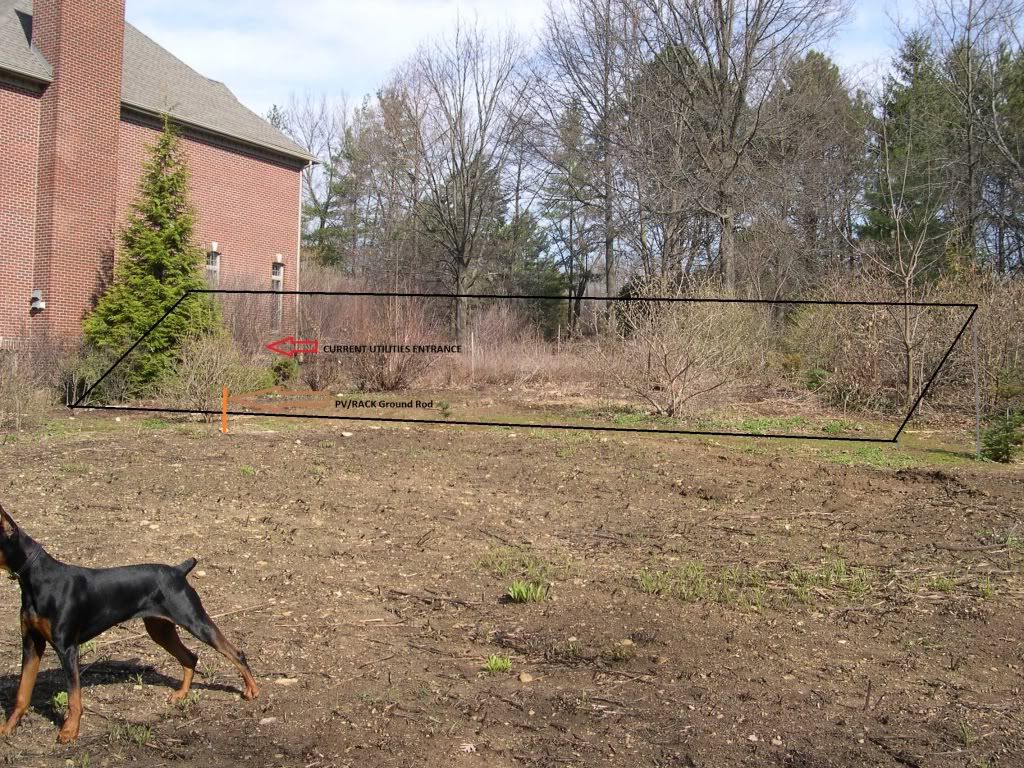
The distance from edge of mount which is closest to house to the utilities is about 40'. Here is the setup at the house: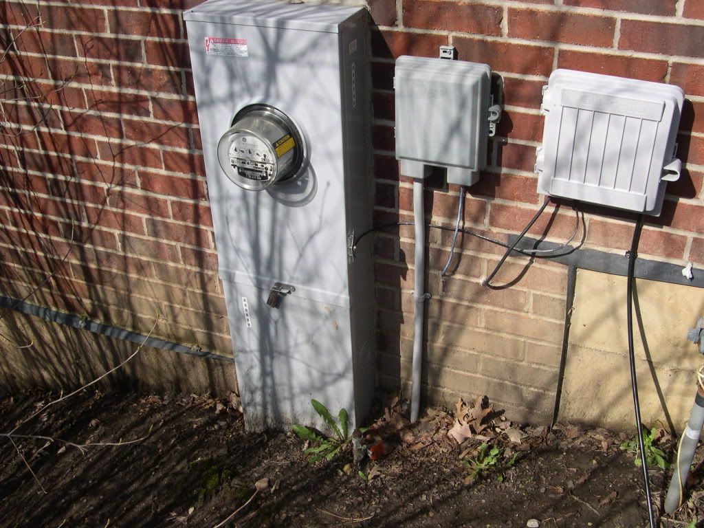
My utility requires an AC disconnect outside.
SO take it from the 4 Enphase branch circuits running into a junction box--what is the bext way to take it from there? I appreciate the assistance! -
Re: Another Grounding Question
i think you can run the pv wires with the ground to the area of the disconnect so it can go to the main ground rod before entering your house. that would take care of my beef with a ground wire entering a building without going to ground first. that could be a box or even a disconnect mounted to the building so the ground wire can go straight to the ground rod from inside the box. i'm not sure how you planned to go to the house, but that would allow for grounding that pv ground wire before it goes into the house.
the ground rod at the pvs i think is optional and somebody can double check me on that, but if you elect to put an 8ft ground rod there, then you will need to run at least a #6 bare copper wire underground to intertie the 2 rods. technically the 2 rods being tied together aren't required at all in the nec, but take it from me you should do it that way. that would mean eliminating the ground wire with the pv wires which i believe wiles mandated in a later edition. for the underground wire to intertie the ground rods don't bury it until you allow the inspector to see you took this step in grounding the pvs this way making the 2 intertied rods as one huge grounding system. if he insists upon a ground wire with the pv wires (which i don't believe it's mandated in 2003) then keep the underground ground wire connected and (you didn't hear this from me) disconnect the one he would insist be run with the pv wires later so that you don't have 2 ground wires posing the problem of possibly creating ground loops. again, this assumes you putting in an 8ft ground rod at the pvs in addition to grounding it at the entrance to the building with the main ground rod.
i hope somebody has the 2003 edition to recheck me as i don't want to advise you wrongly. better yet, just run it past the inspector as to what you plan to do and show him the pics too so he can visualize it better. it helped me visualize your circumstance better. i hope i'm helping you.
ps- i don't think it's legal to eliminate the ground rod connection at the building for a remote one like having one at the pvs only as wiles may have suggested. in any case, it would not be good practice to just have a ground rod at the pvs only for that leaves the ground lead going to the house susceptible to the same pickup of lightning or emp that could go into the building.
pss- be sure to have enough clearance off of the ground for your array as snow would pile up there and that would shade things. -
Re: Another Grounding QuestionOk--since my local inspectors are working off 2003 code, and have absolutely no experience with solar, help me do it right/safe.......pleeeeeeease
Niels way is the correct way to bond the system grounds. The inspector might think it's overkill but in my 30+ years of working on structures at some of the most lightning prone areas in the world it is the 'de facto standard'. -
Re: Another Grounding Questioni think you can run the pv wires with the ground to the area of the disconnect so it can go to the main ground rod before entering your house. that would take care of my beef with a ground wire entering a building without going to ground first. that could be a box or even a disconnect mounted to the building so the ground wire can go straight to the ground rod from inside the box. i'm not sure how you planned to go to the house, but that would allow for grounding that pv ground wire before it goes into the house.
the ground rod at the pvs i think is optional and somebody can double check me on that, but if you elect to put an 8ft ground rod there, then you will need to run at least a #6 bare copper wire underground to intertie the 2 rods. technically the 2 rods being tied together aren't required at all in the nec, but take it from me you should do it that way. that would mean eliminating the ground wire with the pv wires which i believe wiles mandated in a later edition. for the underground wire to intertie the ground rods don't bury it until you allow the inspector to see you took this step in grounding the pvs this way making the 2 intertied rods as one huge grounding system. if he insists upon a ground wire with the pv wires (which i don't believe it's mandated in 2003) then keep the underground ground wire connected and (you didn't hear this from me) disconnect the one he would insist be run with the pv wires later so that you don't have 2 ground wires posing the problem of possibly creating ground loops. again, this assumes you putting in an 8ft ground rod at the pvs in addition to grounding it at the entrance to the building with the main ground rod.
i hope somebody has the 2003 edition to recheck me as i don't want to advise you wrongly. better yet, just run it past the inspector as to what you plan to do and show him the pics too so he can visualize it better. it helped me visualize your circumstance better. i hope i'm helping you.
ps- i don't think it's legal to eliminate the ground rod connection at the building for a remote one like having one at the pvs only as wiles may have suggested. in any case, it would not be good practice to just have a ground rod at the pvs only for that leaves the ground lead going to the house susceptible to the same pickup of lightning or emp that could go into the building.
pss- be sure to have enough clearance off of the ground for your array as snow would pile up there and that would shade things.
Ok--It's getting a bit clearer now! I do appreciate your efforts here. So my grounding wire from the inverters and rack could conceivably tie to the neutral in the junction box, travel through the conduit to the disconnect, where you would attach a copper wire to the outside grounding rod near my meter?
alternatively
Run my copper grounding cable from inverters to racks to grounding rod at the array, and tie that rod to rod at the house with buried #6 copper wire. Neutral in the branch circuit wiring goes unused then?
Let's look at this guy's install---
http://www.builditsolar.com/Projects/PV/EnphasePV/Wiring.htm
Would you fault him because he has the ground rods(one at array, one at house) both connected via the PV's wiring? If it was your choice in his case, would you eliminate the rod at the array and do everything else the same? -
Re: Another Grounding Question
His PV power/Utility ground tie looks ok for a residence. It's all on the exterior and there's only a very short loop from the PV ground to the utility ground connection on the PV feed breaker box. I would have used metal conduit between the disconnect switch and the breaker box and dressed my grounds better (removing the loops).
My 2c worth. -
Re: Another Grounding Question
i keep forgetting you have an enphase system in mind. where are you going to make the connection to the utility at, in that box outside or inside the house?
outside is best and that wiring link i gave before looks very much like what you have on your exterior wall. if it is to be outside then the pv ground will go straight to the ground rod and will not be connected to the neutral. the neutral connection happens only once in a home and it's already done in the utility breaker panel box.
maybe this diagram will help you too.
http://www.enphaseenergy.com/downloads/Enphase_Wiring_Diagram_1_240_Single_Phase.pdf
ps- note that in the above diagram that the ground wire from the utility box and the pv ground wire appear like they are tied together and then go to the ground rod. this is not so as both wires will individually go to the ground rod and be connected to it with their own connector. you have the one from the utility ground already on it and the one from the pvs shall go straight to the ground rod also and connected with its own connector in the same fashion. the ground rod will almost be like a bus in this case.;)8) -
Re: Another Grounding Question
You need to run 4 wires to the array.
Hot 1 (L1)
Hot 2 (L2)
Neutral
Equipment Ground (green or bare)
The neutral is not "unused" it must be connected to the Enphase AC output pigtail cable. It just has nothing to do with grounding, since that bond is already done in the main house panel.
The Enphase doesn't have an equipment grounding conductor in its AC ouput cable, so your EGC system ends at the junction boxes where the Enphase pigtails connect to the normal wiring.
Then you also have a ground rod, which you use to ground the PV frames and the Enphase chassis.
And, if you want, you can go the overkill route and ALSO run a buried bare #6 to connect that array ground rod to the ground rod at the house. Personally, I would.
I have nothing against overkill, and though I may argue with these guys over code interpretation, I actually do agree that it's best to tie ground rods together unless they are very far apart. 40' isn't far in my opinion.
So really, you have 5 wires between the array and the house - the four in the conduit to the junction box which is connected to the Enphase AC out, and the separate buried bare #6 to bond the ground rods together. -
Re: Another Grounding Questioni keep forgetting you have an enphase system in mind. where are you going to make the connection to the utility at, in that box outside or inside the house?
outside is best and that wiring link i gave before looks very much like what you have on your exterior wall. if it is to be outside then the pv ground will go straight to the ground rod and will not be connected to the neutral. the neutral connection happens only once in a home and it's already done in the utility breaker panel box.
maybe this diagram will help you too.
http://www.enphaseenergy.com/downloads/Enphase_Wiring_Diagram_1_240_Single_Phase.pdf
My main and subpanel(400A service) is on the basement wall right behind the meter in that picture. I still ponder where to do the connection. Since I will have 4 branch circuits, each will will need a 15A breaker somewhere along the line, and the utility requires a disconnect that is outdoors and not fused. Do I get a disconnect that has 4 inputs and go from there to the basement subpanel, or subpanel outside, then to disconnect, or ??? I guess I have to inquire about how the various setups would affect the Envoy communications for monitoring as well.
I want to reassure you all that I am doing this all as a precursor to my actual electrician handling the wiring. First time solar install for him, so he too will appreciate all these little bits of info. -
Re: Another Grounding QuestionYou need to run 4 wires to the array.
Hot 1 (L1)
Hot 2 (L2)
Neutral
Equipment Ground (green or bare)
The neutral is not "unused" it must be connected to the Enphase AC output pigtail cable. It just has nothing to do with grounding, since that bond is already done in the main house panel.
Sorry--poor choice of words on "unused"The Enphase doesn't have an equipment grounding conductor in its AC ouput cable, so your EGC system ends at the junction boxes where the Enphase pigtails connect to the normal wiring.
Then you also have a ground rod, which you use to ground the PV frames and the Enphase chassis.
And, if you want, you can go the overkill route and ALSO run a buried bare #6 to connect that array ground rod to the ground rod at the house. Personally, I would.
I have nothing against overkill, and though I may argue with these guys over code interpretation, I actually do agree that it's best to tie ground rods together unless they are very far apart. 40' isn't far in my opinion.
So really, you have 5 wires between the array and the house - the four in the conduit to the junction box which is connected to the Enphase AC out, and the separate buried bare #6 to bond the ground rods together.
Does this create a grand ground loop? Let me see if I have it straight. Ground rod at array has the Enphase chassis and rack ground attached. The other end of that ground wire goes into the junction box, attached to a ground wire in the conduit. That ground wire exits at the disconnect and goes to the house ground rod at the meter? If I also bond the two rods together, do I not create the grand loop? -
Re: Another Grounding Question
you get a ground loop when there are 2 paths to the same ground. if you run a ground wire with the output of the enphase microinverters to ground at the main ground rod and tie 2 ground rods together underground (pvs ground would go to the ground rod at the pvs) and then back to the main ground rod underground. that's 2 paths. i don't know if the nec requires the ground wire with the inverter outputs or not, but maybe nsaspook or dwh might know as i do know with pv outputs it's required to a large single gt back in the house under newer nec rules.
i'm sure if your electrician reads what i'm talking about he'd somewhat understand about the 2 ground paths back to the main ground rod that could cause ground loops. -
Re: Another Grounding Question
Bonding the rods doesn't create a ground loop, there will be no current from the PV inverters flowing in that wire. A lightning surge has a very fast rise time and will flow on the path of least resistance (impedance) to ground. That buried #6 will look like a black hole to any potential difference in voltage between the rods. The energy/EMF generated in a grounding system surge is a factor of current and voltage. When you make the resistance to earth as low as possible you reduce one side of the power equation to near zero (voltage) so even with large currents the net power is low.
This is the same effect seen in superconductor coil operation. With zero resistance the current flow in it uses no power because no voltage is generated. -
Re: Another Grounding Question
nsaspook,
with just the bonded ground rods used you would be correct, but adding another overhead path could set up loops. this is like the rule of only bonding once for neutral and ground as you don't want multiple paths that can create problems.
obviously, given a choice i would certainly prefer the bonded ground rods. -
Re: Another Grounding Questionnsaspook,
with just the bonded ground rods used you would be correct, but adding another overhead path could set up loops. this is like the rule of only bonding once for neutral and ground as you don't want multiple paths that can create problems.
obviously, given a choice i would certainly prefer the bonded ground rods.
The only time current will flow in the rod bonding wire or the ground wire with the AC power cable is due either a AC power fault at the disconnect/utility/PV inverter boxes/cables or due to a lighting induced surge. In both cases the circuits are external to the house with the utility rod shunting energy to ground. So yes, there is a loop but not past the house grounding rod and single point grounding for inside the house is maintained.
Categories
- All Categories
- 233 Forum & Website
- 140 Solar Forum News and Announcements
- 1.3K Solar News, Reviews, & Product Announcements
- 181 Solar Information links & sources, event announcements
- 895 Solar Product Reviews & Opinions
- 252 Solar Skeptics, Hype, & Scams Corner
- 22.5K Solar Electric Power, Wind Power & Balance of System
- 3.5K General Solar Power Topics
- 6.7K Solar Beginners Corner
- 1K PV Installers Forum - NEC, Wiring, Installation
- 2.1K Advanced Solar Electric Technical Forum
- 5.6K Off Grid Solar & Battery Systems
- 428 Caravan, Recreational Vehicle, and Marine Power Systems
- 1.1K Grid Tie and Grid Interactive Systems
- 656 Solar Water Pumping
- 816 Wind Power Generation
- 621 Energy Use & Conservation
- 623 Discussion Forums/Café
- 316 In the Weeds--Member's Choice
- 74 Construction
- 125 New Battery Technologies
- 108 Old Battery Tech Discussions
- 3.8K Solar News - Automatic Feed
- 3.8K Solar Energy News RSS Feed