Sun Saver 10 Question and DC gate opener

GreenMachine
Registered Users Posts: 13 ✭
Hi,
I have an Apollo 7100 gate opener that is using a Morning Star Sun Saver 10 regulator.
This is the gate opener. http://www.laornamental.com/Store/product5006.html?prdId=544843
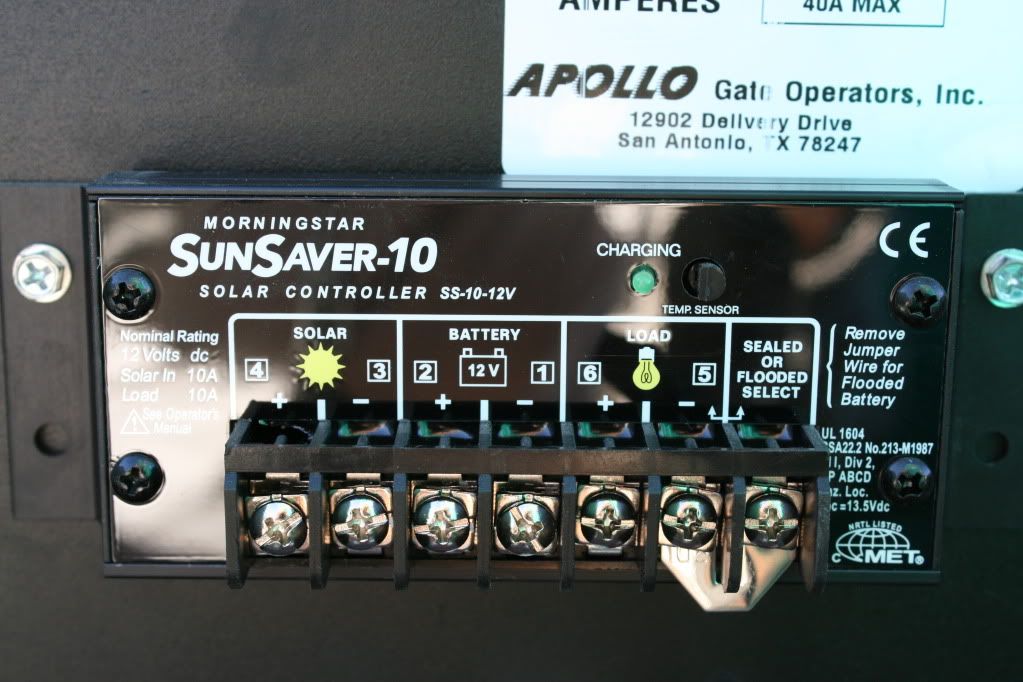
And this is the controller
The problem I"m having is that the solar panel is not charging the battery. Power from the panel is going into the controller but that's about it.
The gate company installed the DC motor supply wires to the battery #1 and #2 terminals, so that both the DC battery and the DC motor wires are both boot-legged on the same #1 and #2 terminals. Is this OK? Shouldn't the motor supply wires be on the load #5 and #6 terminals?
Thanks
Larry
I have an Apollo 7100 gate opener that is using a Morning Star Sun Saver 10 regulator.
This is the gate opener. http://www.laornamental.com/Store/product5006.html?prdId=544843
And this is the controller
The problem I"m having is that the solar panel is not charging the battery. Power from the panel is going into the controller but that's about it.
The gate company installed the DC motor supply wires to the battery #1 and #2 terminals, so that both the DC battery and the DC motor wires are both boot-legged on the same #1 and #2 terminals. Is this OK? Shouldn't the motor supply wires be on the load #5 and #6 terminals?
Thanks
Larry
Comments
-
Re: Sun Saver 10 Question and DC gate opener
No. The "LOAD" terminals are for low Amperage loads like DC lighting - less than 10 Amps I think, considering this is a 10 Amp controller (bigger ones can handle more of course).
If the battery isn't charging it is very likely that the panel is insufficient for the battery capacity.
This is a 10 Amp charge controller. It could handle up to 100 Amp hours of battery, but would need about 175 Watts of panel to do so. -
Re: Sun Saver 10 Question and DC gate opener
Connecting the gate operator to the charge controller at the battery terminals is not bootlegging. It's the same as if you ran the operator wires to the battery and ran the charger wires to the battery - both sets of wires end up connected together whether you do it at the battery or at the charger.
No, the gate operator should not be connected to the load for the reasons Coot specified.
My first question is: Has this rig ever worked in the past or is it a new install?
If it used to work, then you are looking for something that failed. If it never worked, then it could be a bad charge controller, or a bad PV, or a bad battery or the wrong PV or a blown fuse at the battery. -
Re: Sun Saver 10 Question and DC gate opener
Great...glad to know everything was hooked up correctly. Although it made me wonder because the gate company has not been so joyful to deal with, customer service wise.
Yes, this is a new install. Just about three months. The first couple of months the gate was not used much. Maybe once a week. This last month, we have contractors comming in and out on a daily basis. It could be that the battery was never being charged from the beginning and was just running off its original charge.
Over the weekend, I hooked up a battery charger to the gate to keep it operational for the contractors. While connecting the battery charger I heard a electrical noise coming from ther Sun Saver. Before I could figure out that one of the battery terminals was loose on the controller and was arcing off the back panel, it began smoking pretty good. I can't believe it was put on so loose.
So I took it upon myself to buy a new controller. I just recieved a new Sun Saver 10 today, and will install this weekend. It's been over a week since the gate company was out to trouble shoot and I have not heard back from them nor have they returned any of my calls. -
Re: Sun Saver 10 Question and DC gate opener
so is it now working with the newer sunsaver 10? -
Re: Sun Saver 10 Question and DC gate opener
Yea, it does sound like the battery just finally ran down and never did get recharged - or at least hasn't been recharged lately.
If it's a new install that charge controller is probably still in warranty.
Magic Smoke is bad. There should be a fuse in the wire to the battery, and another in the wire to the gate operator to prevent it. The manual doesn't state what size fuse the gate operator needs. I'm a fan of Bussman "Modified Reset" (remove power to reset) breakers:
http://www.wiringproducts.com/contents/en-us/d60.html
In the upper right of your picture, there is a decal that says, "40A MAX". What is that?
If that gate operator can draw that much, then you should probably run the wire from the operator directly to the battery (with a fuse or breaker) instead of connecting it at the terminals on the charge controller. -
Re: Sun Saver 10 Question and DC gate opener
We also have to wonder why this was set up as solar in the first place. No grid power? If the utility is available there's not much point of adding the extra complexity of solar. -
Re: Sun Saver 10 Question and DC gate openerCariboocoot wrote: »We also have to wonder why this was set up as solar in the first place. No grid power? If the utility is available there's not much point of adding the extra complexity of solar.
It's actually very common for gate operators. Since a lot of them run on a 12v battery anyway (so the gate will work even in a power outage) then you either run a trickle charger or a small PV (5w-10w usually).
Depending on the length of the driveway it's often cheaper to use PV than to run an underground power circuit just to feed a 1a trickle charger. -
Re: Sun Saver 10 Question and DC gate opener
One of my neighbors has a gate setup like that. The battery is not meant for constant in/out usage. Couple of times a day is it.
The reason they are used here is the cost of trenching and permits is greater than solar power.
My neighbors was under wired. His was connected the same way where the motor and battery were connected at the controller. Problem is they used 14ga wire to the battery and 10ga wire to the motor. We moved the motor connection directly to the battery and he has not had a problem since. -
Re: Sun Saver 10 Question and DC gate opener
The use of 12VDC is an obvious choice. But this whole experience proves the solar recharge is a bit "penny wise, pound foolish". Obviously the panel is undersized for the battery and if it gets any more than occasional use ... dead battery. I'm glad I don't live where they make it a major headache to run a bit of wire to properly power a gate. And my driveway is 1 km long! Mind you, the gate is operated "manually".
vcallaway is right: the motor should be wired directly to the battery, not to the controller. -
Re: Sun Saver 10 Question and DC gate opener
It depends on the gate operator. Screw drive swing gate operators don't draw much, so they could be connected to the terminals on the charge controller. But if his operator can draw 40a, then yea, it should draw directly off the battery.
From the install manual for a Mighty Mule setup using dual swing gate heavy-duty screw drives:
http://www.mightymule.com/PDF/Manuals/FM502-Mighty-Mule-b-electric-gate-openers.pdf
"POWER
• The system is powered by a 12 Vdc, 7.0 Ah, sealed, rechargeable acid battery.
• Battery charge is maintained by a 120 Vac, 18 Vac output transformer rectified to 14.5 Vdc (20 VA) through the GTO control board. One (1) blade-style control board fuse rated for 25 A.
NOTE: The transformer should not be directly connected to any battery. Do not replace fuses with higher ampere rated fuses; doing so will void your warranty and may damage your control board.
• Battery charge is maintained by GTO Solar Panel Charger: float voltage of 14.5 Vdc output from a 19 3/8" x 8 1/2" silicon alloy panel. Generates minimum of 5 W at 300 mA. A gated diode on the control board prevents battery discharge."
EDIT: The 5w PV is good enough for the 7ah battery in the Mighty Mule, but I think the OP's Apollo recommends a 105ah battery, so I'm curious to know what size battery and PV he's actually got. -
Re: Sun Saver 10 Question and DC gate opener
Thanks for that, dwh!
Like you say; looking at that company info it makes sense. That system would work.
But there are hints about the OP's installer which indicate maybe they didn't exactly follow instructions? On the other hand, none of them are designed for heavy traffic use and it could just be overwhelmed by contractors going in and out. -
Re: Sun Saver 10 Question and DC gate openerCariboocoot wrote: »Thanks for that, dwh!
Like you say; looking at that company info it makes sense. That system would work.
But there are hints about the OP's installer which indicate maybe they didn't exactly follow instructions? On the other hand, none of them are designed for heavy traffic use and it could just be overwhelmed by contractors going in and out.
Well, I didn't notice that 40a sticker at first glance, but the installer could have done what vcallaway described and used smaller wire from the controller to the battery - which would have been a dumb thing to do.
If the installer used the same size wire, then both connections could be made at the charge controller - but personally, for a gate operator that can draw up to 40a, I would want something more secure than stuffing two fat wires under one terminal screw. A couple of #12s I could see, but 10s would be pushing it.
Putting two wires under one screw isn't bad by default. Intermatic timers have the same sort of terminal screws and they are quite strong and it's very common to see more than one wire under those screws:
http://www.intermatic.com/products/timers/mechanical time switches/24 hour dial.aspx
If the OP's Apollo does have a 105ah battery, then it should handle quite a few cycles before being drained, but how many cycles per day would be determined by the PV size. -
Re: Sun Saver 10 Question and DC gate opener
Thanks for the replies guys. I may have overstated the useage of the gate on a daily basis. The gate is open in the morning...stays open all day and then gets closed. If the contractors leave for lunch it may get used again. So that's about it.
The reason I have a solar gate is because the property is not currently hooked up to the grid. The property is basicly an undeveloped heavy industrial piece of land we are using for our business. I am borrowing power via an extension cord from a neighboring business to power the battery to my gate. Hope this helps explain some of the mystery.
I will be at the property this weekend and will check wire sizes and take some more pictures. I believe battery and PV sizes were recomendations from Apollo.
I still have not heard back from the gate company so it looks like that I may be on my own for the fix. -
Re: Sun Saver 10 Question and DC gate opener
Ok...I'm back with pix.
First of all I want to thanks everyone for the help so far. It's amazing how you can spend good money on something and and wind up at this point.


-
Re: Sun Saver 10 Question and DC gate opener
Battery
#14 wire coming from motor


Gate installer used #14 wire on everything
-
Re: Sun Saver 10 Question and DC gate opener


#1 is red and black pair coming from PV
#2 is red and black pair going down to battery
#3 is red and black pair coming up from battery and going into board #4a
#4 is red and black supply line from motor going into board #4a
I wish I would have taken a pic before I pulled the wires off the SunTrek 10. I can't remember which terminals of the controller were doubled up.
I have not got a clue what I am doing here, so please give me instructions step by step. Also, what size fuses am I going to need?
Thanks
Larry -
Re: Sun Saver 10 Question and DC gate opener
If you wanted, get an inline fuse from the auto parts store for 15-20 amps each (14 awg wire is good for 15-20 amps), place it near the battery in the + lead to the solar charge controller...
The same thing should be done for the + lead to the controller board too... The fuses are to help prevent the wiring from overheating and causing a fire if there is a short circuit in the wiring/controllers/motor.
The controller also has several sets of fuses--So, at least the wires leaving the controller are protected.
On the other hand, you can run the system without the extra fuses if there is nothing nearby to catch fire (that you care about--adding extra and fuses/connections is another point of failure for a small system). You just need to be careful that all cables are properly dressed, tied together, run through rubber/plastic grommeted holes, etc. so that the insulation cannot get worn through and shorted--And that the wires are not "pulling" on the electrical connections too hard where they could pull out and short.
When reconnecting everything--Check the charge controller manual and see if the battery should be connected first or the PV panels. I probably would throw my jacket over the solar panels just to lessen the chances of sparks (surprise to you) when the panel wires are first connected to the charge controller.
-BillNear San Francisco California: 3.5kWatt Grid Tied Solar power system+small backup genset -
Re: Sun Saver 10 Question and DC gate opener
Do I see a pair of 35 Watt panels? And one 32 Amp hour battery?
I don't see any current rating on the gate motor. Can't be 40 Amps.
As for 14 AWG wire everywhere ... Maybe you want to check with an Ammeter and see what sort of current is actually going through the wires. -
Re: Sun Saver 10 Question and DC gate opener
Okay.
Apollo states in their spec sheet for the 7100ETL that they recommend a 105ah battery which, fully charged should provide 300 cycles or 30 days of reserve. But, in the actual manual they say 33ah minimum so that battery should be fine.
The 3a fuses on the control board protect other things that can be powered by the control board, such as the radio receiver, photo-eye and alarm siren. The 15a fuse supplies the emergency bypass (that's just a way to manually power the motor to open in case the control board is blown - not used unless you have to). None of those fuses protect the control board itself.
I can't find anything in the Apollo docs which indicate what size fuse (if any) should be used for the control board feed. I don't see any fuse in your pics. The Apollo decal does say 12vdc and 40a max. I would call Apollo and ask them what size wire and fuse should be used.
Though the motor wires are #14, they go into that terminal block, and the wire from the control board that feeds into the other side of the terminal block looks smaller than #14. Also the pair from the battery to control board looks smaller than #14. The connectors at "4a" in your pic, and the wire were factory supplied by Apollo I'm sure, so if those wires are smaller than #14, then nothing bigger than 14 should be needed anywhere.
Basically, it looks okay as it is. I would put a 15a fuse in the positive wire from the charge controller to the battery just on general principles.
According to your original post, the wires feeding power into connector 4a (pair 3 in your pic) were originally connected to the battery terminals on the SunSaver, along with the wires feeding down to the battery.
I'm guessing that after you disconnected the SunSaver, you ran those wires down through the hole to the battery when you connected the AC powered battery charger?
Either way is fine actually. Whether you connect the control board power feed directly to the battery, or connect it to the battery screws on the SunSaver - you are still connecting the power feed from the control board to the wires that go from SunSaver to battery...you are just doing it at one end of those wires or the other. Top or bottom - doesn't matter since the wires from SunSaver to battery are bigger than, or at least as large as, the wires that feed the control board.
Personally, I would connect the power feed to the control board at the battery in a nice secure fashion, rather than under the screws on the SunSaver, but that's just a preference - either way is fine.
I would also put a fuse in the positive wire feeding from the battery to the control board. Looking at the size of the feed wire, I would bet that a 15a fuse is enough - but would check with Apollo to be sure.
Were those PVs actually made in '98? Where did the installer get those things?
Still, 70w of PV should be plenty to keep that battery topped off. I wonder what the specs are for those panels and are they connected series or parallel and what is the voltage coming into the SunSaver?
To charge that 12v battery, the voltage coming into the SunSaver from the PV should be greater than 15v. That is, greater than 15v when UNDER LOAD.
According to your OP, the problem was that the battery wasn't getting charged. That could be due to loose connections or a bad SunSaver.
But it could also be that the PV are putting out less than 15v under load, in which case there just isn't enough power to charge the battery.
It could be that the PV panels are connected in parallel and the voltage is too low, in which case they might need to be wired in series instead to get the voltage up over 15v under load.
What is the open circuit (no load) voltage coming IN to the SunSaver from the PV (in full sun)? -
Re: Sun Saver 10 Question and DC gate opener
To the point, what is the voltage from the solar panels wires? Also, if you can, use a current meter in series with the solar wire and measure the current from the panel
Those panels are very old being 1998 vintage, I would suspect they don't work or are Asi panels and higher voltage than would be used in this application
I would demand from the installer that new equipment be used if that was the intent of your contract -
Re: Sun Saver 10 Question and DC gate openerOkay.
According to your original post, the wires feeding power into connector 4a (pair 3 in your pic) were originally connected to the battery terminals on the SunSaver, along with the wires feeding down to the battery.
I'm guessing that after you disconnected the SunSaver, you ran those wires down through the hole to the battery when you connected the AC powered battery charger?

Were those PVs actually made in '98? Where did the installer get those things?
What is the open circuit (no load) voltage coming IN to the SunSaver from the PV (in full sun)?
No I did not run any wires down through the hole to the battery.
I just can not remember how the wires were originally connected to the SunSaver.
As you can see in these pics there are no more wires. Should there be another set of wires?
I have no idea why I was sold 10yr old PVs.
The last thing the installer told me was that 17v were coming down from the PVs to the SunSaver. But no power was coming out. I will double check this when I get a chance. -
Re: Sun Saver 10 Question and DC gate openerGreenMachine wrote: »No I did not run any wires down through the hole to the battery.
I just can not remember how the wires were originally connected to the SunSaver.
As you can see in these pics there are no more wires. Should there be another set of wires?
I have no idea why I was sold 10yr old PVs.
The last thing the installer told me was that 17v were coming down from the PVs to the SunSaver. But no power was coming out. I will double check this when I get a chance.
Okay, so from looking at that pic, the installer ran a single short #14 from the battery positive to that yellow wire nut, and at that point you have one wire from the charge controller, and another wire to the control board.
Looking at the battery negative, it seems that he ran both wires from the charge controller and the control board to the battery post instead of wire nutting them together.
Either way is fine. I would have run both positive wires to the battery terminal the way he did with the negative, and put inline fuses on them both. But that's just my nit-picky way of doing things. I am a journeyman electrician with 12 years experience, of which 1.5 years was as the house electrician for a gate company and I don't find any serious faults with this guy's work except for "WTF? 12 year old PV panels??"
So the connection at the charge controller is just one pair of wires from the PV, and one pair down to the battery. That's proper.
According to the SunSaver manual, the max PV voltage that the -10 can handle is 25v, so if the PV array is in fact putting out 17v, then that's exactly in the sweet spot. Amperage on 70w of PV @ 17v is only a little over 4a, and the -10 can handle 12.5a so no problem there, and 4a is plenty to charge that battery.
So, either the SunSaver is bad, or the PV array isn't putting out enough current to charge the battery (or the connections were loose). IF the array is in fact putting out 17v, which at this point is hearsay.
Note that the manual says to connect the battery first, then the PV. The terminals are numbered on the label, and that is the recommended connection order.
1. Battery -
2. Battery +
3. Solar -
4. Solar +
5 and 6 are for the load. The load can be up to 10a, and is controlled by the Low Voltage Disconnect (LVD). The load will be disconnected if the battery voltage drops below 11.5v and reconnected when it gets up to 12.6v.
The jumper tells it to charge the battery to either 14.4v for flooded or 14.1v for sealed. Yours is sealed so leave the jumper in place for 14.1v.
Also note that the manual says that shorting battery or PV *will* damage the charge controller.
Also, here is something nifty:
"7.1 TESTING WITH A POWER SUPPLY
Normal SunSaver operation can be tested with a power supply
used in place of either the PV array input or the
battery. To be certain the SunSaver will not be damaged,
observe the following cautions:
• Current limit the power supply to no more than one half the
SunSaver rating.
• Set the power supply to 15 volts DC or less for 12V systems
and 30 volts DC or less for 24V systems.
• Connect only one power supply to the controller."
So, there IS a way to bench test that controller. If it tests out fine, then the problem would definitely be the PV. -
Re: Sun Saver 10 Question and DC gate opener
My reading is the PV is toast ... 17V would have a VMP of about 12-13 volts , since the charge controller is a PWM model
Some basic testing with a DVM is in order at this point -
Re: Sun Saver 10 Question and DC gate opener
Ok I'm back!
My wife confronted/suprised the gate installer at his shop. She got him to install a new SunSaver 10. I took a volt reading from the PV array and I only got 12.5 volts. The trickle charger was removed about one month ago. Over the last week we have noticed the gate was moving slower and slower. So I believe we have been just running off the fully charged battery, which was not being recharged. So you guys were right about the panels not putting out enough juice.
So I must replace the PV. Exactly how many volts do I want coming from the new panel? And what size panel should I be getting? I am tired of this bare minimum stuff. Please include links!
Should I upgrade the battery also?
Thanks for the help everyone!
Larry -
Re: Sun Saver 10 Question and DC gate opener
Any 12v nominal (greater than 17volts open circuit - VOC) PV of 20w or above should be sufficient.
This should be fine:
http://store.solar-electric.com/so20wamusopa.html
But you should make the solar installer pay for it, since he supplied you with defective PV modules.
EDIT: In the meantime - charge that battery. By continually running it so low on charge you are significantly shortening its life. -
Re: Sun Saver 10 Question and DC gate opener
Thanks for the help.
What is the difference between the Solartech SPM020P-D and the SPM020P seen here http://www.ecodirect.com/Solartech-SPM020P-20-Watt-12-Volt-p/solartech-spm020p.htm
Vpm 17.2 and Voc 21.7 Which one of these reading will I see on my DVM?
Also, it seems that I do not gain much between the 20w and the 30w panel seen here
http://www.ecodirect.com/Solartech-SPM030P-30-Watt-12-Volt-p/solartech-spm030p.htm -
Re: Sun Saver 10 Question and DC gate opener
if you disconnect the pv so that it is not connected to anything and you measure the voltage being outputted by the pv in decent sunlight the voltage will read the voc of about 21.7v. voc stands for voltage open circuit. it would be too difficult to pin the vpm, or vmp as it is stated either way, for measurement as loads and solar intensities vary the max power point.
the difference in the pvs is 50% more power is available from the 30w pv over the 20w pv. -
Re: Sun Saver 10 Question and DC gate openerGreenMachine wrote: »What is the difference between the Solartech SPM020P-D and the SPM020P seen here http://www.ecodirect.com/Solartech-SPM020P-20-Watt-12-Volt-p/solartech-spm020p.htm
Dunno. Their web site gives an error when trying to open up the spec sheet on the 020P:
http://www.solartechpower.com/products-ALL.html
Drop 'em an email and ask.Vpm 17.2 and Voc 21.7 Which one of these reading will I see on my DVM?
With the solar panel not connected to anything, you can test the Voc and Isc (current short circuit). There is some fudge factor since the PV rating was established under perfect lab conditions, so in the field as long as the Voc and Isc are fairly close then that's acceptable.
Vmp is volts max power, but you won't actually see that with your meter unless you had an MPPT controller. But you don't, you have a PWM (pulse width modulation) controller. A PWM controller just connects the solar panel to the battery straight through, but it does it in fast pulses.
Since the PWM is straight though, you'll see Voc on the PV side of the controller, and battery voltage on the battery side of the controller - ONLY when the controller is not charging the battery...which is pretty much never when the sun is shining. You'll see Vmp on both sides of the controller when it is charging the battery (since both sides are connected together straight through).
However, the Vmp you see WON'T be what's on the nameplate rating. The voltage under load (Vmp) is dependent on the resistance of the load. An MPPT controller will use an algorithm to figure out what that should be and create a load which will max the output of the PV module, and it will vary that as needed to continuously pull the max it can get from the PV.
But a PWM controller doesn't do that, so the volts under load will vary depending on the battery's state of charge (resistance). In other words...you can't really measure true Vmp without specialized gear to create the proper load. You can however measure what the volts are when connected to the battery which can more or less be considered to be " the Vmp in that situation".Also, it seems that I do not gain much between the 20w and the 30w panel seen here
http://www.ecodirect.com/Solartech-SPM030P-30-Watt-12-Volt-p/solartech-spm030p.htm
Well, yes and no. 30w is 150% of 20w, so that's a noticeable difference. You have a fairly beefy gate motor, so 20w is the *minimum* I'd use. 30w would be better. If you used the gate a lot, then I might go even higher, but only if it turned out that 30w wasn't enough to keep up with the normal day to day usage. -
Re: Sun Saver 10 Question and DC gate openerGreenMachine wrote: »Ok I'm back!
.... So I believe we have been just running off the fully charged battery, which was not being recharged. So you guys were right about the panels not putting out enough juice.
I am tired of this bare minimum stuff. Please include links!
Should I upgrade the battery also?
Larry
Yes, you paid full price for a worthless 10+ year old panel
Buy this one http://store.solar-electric.com/spm030p.html
Not needed, the above panel should take care of all your needs, even with heavy use of the gate -
Re: Sun Saver 10 Question and DC gate opener
Hi all I'm having similar problems As op
Though all my gear was up to date new
And was sold a 24 volt system with 2 x 25 w panels
Regulator and 2x25 ah 12 volt battery's
All set up as a 24 volt system
1 st year of install worked great all summer
But come fall and 2 - 4 days of cloud cover
The system discharged over night
The company came to check changed my battery's over to
2x18 ah 12 volt battery's and changed the regulator
And it worked fine for the rest of the year
Now 2 season fall again
And same issue
I'm baffled there is no issues during daytime when sun is up
I can open and close 30 times in a row no issues at all
But and therefore I'm sure it's dischaging over night
But why ? And how where is the problem
I know there is a current draw to the gate unit but it shouldn't
Discharge the batteries overnight like that should it


Categories
- All Categories
- 229 Forum & Website
- 136 Solar Forum News and Announcements
- 1.3K Solar News, Reviews, & Product Announcements
- 178 Solar Information links & sources, event announcements
- 892 Solar Product Reviews & Opinions
- 252 Solar Skeptics, Hype, & Scams Corner
- 22.5K Solar Electric Power, Wind Power & Balance of System
- 3.5K General Solar Power Topics
- 6.7K Solar Beginners Corner
- 1K PV Installers Forum - NEC, Wiring, Installation
- 2.1K Advanced Solar Electric Technical Forum
- 5.6K Off Grid Solar & Battery Systems
- 428 Caravan, Recreational Vehicle, and Marine Power Systems
- 1.1K Grid Tie and Grid Interactive Systems
- 655 Solar Water Pumping
- 816 Wind Power Generation
- 620 Energy Use & Conservation
- 622 Discussion Forums/Café
- 316 In the Weeds--Member's Choice
- 74 Construction
- 125 New Battery Technologies
- 107 Old Battery Tech Discussions
- 3.8K Solar News - Automatic Feed
- 3.8K Solar Energy News RSS Feed