Earthing Help! (System equipotential bonding vs Array bonding vs AC conductor PEN earth stake)

I've been doing a lot of reading trying to get my head around what the right grounding system is to implement for a theoretical small PV minigrid (<10kW with distribution distances <300m), isolated from an external AC grid.
1. I understand that the metal PV array frame/roof should be grounded to prevent floating potential, as voltages can be induced on the frame by the inverters high frequency switching components.
2. Similarly, all equipment casing should be bonded and connected to earth in case of faults, for safety purposes.
3. And finally, the earth and neutral will be bonded at one point after the inverter (if not already done inside the inverter), and then protection using RCDs installed downstream.
The PV negative line will only be grounded if ground-loop protection is installed (and this will usually be via the inverter anyway).
What is now confusing me, is if these separate requirements should use separate earthing conductors.
These technical specifications online seem to indicate a separate earthing rod for equipment casing to the PV array, and again a separate one for the AC Neutral-Earth link (but I may have misinterpreted it). https://www.drdnepmyanmar.org/sites/drdnepmyanmar.org/files/nep-document-docs/supportdoc2_minigridtechspecs_v2.pdf
On the other hand, this document seems to indicate multiple earth electrodes, but that they are all tied via equipotential bonding/ earthing cables. https://drive.google.com/file/d/1fjRi5QlU0k92Qw_6NjTdZ4u2xhBxFX9d/view?usp=sharing
And some other sites I've read keep insisting on how there must only be one earthing rod present to avoid ground loops (although perhaps they only mean on the AC side, and the chassis/equipment grounding and PV array grounding is different)
Would anyone be able to help clear this up for me? Is it dangerous/disadvantageous if the grounding rod for all 3 of the above is connected? If the PV grounding is done via the inverter, I assume that it relies on the equipment casing to be grounded (not the AC output ground, unless this is actually tied in the inverter anyway?)?
And to add to it all, what are your thoughts on grounding the negative terminal of batteries. I saw it drawn on the datasheet for an Xtender Inverter, but again I'm unsure if is always the safest option. The first link says that grounding of DC conductors should never be done directly as this complicates the protection and inspection requirements, but if the equipment is not galvanically isolated from the AC side then virtual earthing is allowed only via the AC side in one location - does that mean that a non isolated system would already be connected to the AC ground via the inverter's AC output?
I found this forum post about grounding batteries and it seems to indicate that it is in fact safest to directly ground the negative terminal when the system is galvanically isolated (contradicting the first link), and it should be a shared ground with the AC ground, however the permission to ground the negative terminal was stated in the datasheet. https://forum.solar-electric.com/discussion/356323/should-negative-on-battery-bank-be-tied-to-ground
Perhaps this is something super complicated and will vary inverter-to-inverter, and if I saw the battery grounded on one inverter's example wiring, then that means it should be done? When a diagram shows multiple ground symbols, does that indicate they mean using separate non-connected earthing rods, or is it just a simpler way of indicating everything being at the same earthing potential, and therefore the same rod can be used?


Obviously this is for a system with an AC in from a grid, but in an insolated system then the stuff on the left wouldn't be there. To make it safe, then the installer would have to add their own ground stake, and tie neutral and live at the AC-out (please do correct me if I'm wrong).

Also just a side note, for a system this small, I think TN-S seems like the most straightforward. Is that right? The connection between earth and neutral being done once at the AC inverter, with an RCD between neutral and live, and then neutral, live and earth being distributed separately to consumers.
Thank you so much!!! I'm thoroughly confused about all this even having been reading various articles for days...
Comments
-
Welcome to the forum Natashaxh,
Your post went into moderation/review because of multiple links (and you are a new member)... I have approved and you should not be "moderated" again.
You have a lot of questions there... It will take a bit of reading to understand your question...
A couple questions on my side... I guess you are in the UK?
Do you have issues with local lightning strikes?
Is this a basic Utility powered system with Solar backup?
Any backup genset?
Is this a fixed home/cabin/office or a Caravan/Vehicle?
Any special loads (radio transmitters/HAM/arc welders/etc.)?
Do you have a link to the inverter system you are thinking of using?
-Bill "moderator" B.Near San Francisco California: 3.5kWatt Grid Tied Solar power system+small backup genset -
Hi Bill,
Thank you for your quick response! Sorry I didn't notice it sooner.
Yes I'm in the UK, though I'm designing a solar minigrid for use in Tanzania.
I don't believe lightening strikes are common in the area.
It is for fixed installations in off-grid communities, so the system is standalone (the solar and batteries operate in isolation from the grid, with no backup genset).
Interesting you should ask about special loads. We've run milling machines off previous installations using soft starters to help the inverters cope with the inrush currents (e.g. a 10kW system running a 2.2kW milling machine will still only just manage to provide the start-up currents with a soft starter). We were hoping to test a small variable power arc-welder off the system too, though haven't yet purchased one to try. And we've also previously installed a solar system for a radio transmitter but the lead-acid batteries died within a few months (I think they'd been sat in a warehouse for too long prior to installation, and we used more than recommended in parallel. That particular installation is the only one which had a grid changeover option, and the solar is now only powering the transmitter during the daytime). I'd be interested as to why these 'special loads' might impact my initial questions though, and why systems for radio transmitters are special cases. Perhaps we overlooked something major when installing the system!
I've attached an image of the system I'm designing. The screenshots in my previous post were taken from the datasheet of the inverter (Studer XTM4000). I'm planning to use two of them in parallel to get to 7kW. A link to the inverter can be found here: https://www.studer-innotec.com/en/product-details/xtender-series/xtm-4000-48-298
One immediate flaw in my wiring diagram that I can see now, having done more reading since designing the system, is that due to the current 'floating' batteries, there should be a fuse in both the negative and positive line. Or I should ground the batteries (but as previously mentioned, I'm confused why some sources say this should never be done where the DC side is galvanically isolated from the batteries).
You can see I also chose to connect the protective earth for all the casing, and the AC earth, to the same earth stake. I will also need to add a note that the PV mounting array (metal) should also be linked to the same grounding system. (Unless you recommend that separate earth stakes are used, as some sources seem to indicate? Perhaps there isn't a 'right' way of doing it, and different countries/installers have different preferences?
Thank you! And I completely agree I put a bit too many questions into that first post. It would be incredible if you could help me get the number of grounding stakes straight in my head though! Any more details needed, please ask away.
-
I also want to add an RCD to that diagram in the distribution box (between the main breaker and the South/North breakers) before any power is distributed to schools/churches/homes etc.
-
Note: I fixed a bad mistake below--Blue is "Neutral" for Europe--NOT BROWN. -BB 7/11/2022
The reason I asked about "special loads"... A typical off grid home typically has small loads that run for hours at a time. A large AH Battery bank (i.e., hours or many hours of constant discharge a day) vs large induction motors that may run short periods of time (like your machine shop). Flooded Cell Lead Acid batteries have lots of capacity, but do not have (that high) of surge current.
Typically an off grid system may run a 20 Hour discharge rate. Say 5 hours an evening for 2x evenings (10 hours) with 50% planned discharge (another 10 hours in extra capacity) for longer battery bank life.
You can get AGM and Li Ion batteries that will quite happily support a 2 hour, 1 hour, or even faster discharge rate. Allow you have a smaller battery bank but support these high surge currents.
Other issues... Grounding for Lightning control. Radio transmitters that may need grounding for better signal propagation, plus the issue of "attracting" lightning.
Other issues--As you have found out, FLA batteries have repetitively high self discharge. At "room temperature" (25C/77F) FLA batteries need to be recharged about once a month to keep them above ~75% State of Charge (when Lead Acid batteries fall below that, they start sulfating faster and faster--Month to weeks to even days). Sulfation results in a permanent loss of battery capacity and life.
AGM and some other types of sealed lead acid batteries can store upwards of 6 months between charging at room temperature.
Li Ion batteries can go 6-12+ months between charge.. And Li Ion batteries (in general) do not have to be kept at a specific SoC range--They will not age any faster if not kept fully charged (the typical rule of thumb is to keep most Lithium type batteries between 10% to 90% SoC--And many believe that around 40-50% SoC storage will have the longest life--Although not always a clear in specifications if true or not).
For the Mill, and other machinery... You might look into using VFDs (variable frequency drives). They can be programmed to have almost zero surge current (they start at a low frequency and then spin up to programmed frequency over a few seconds, or however long you program). VFDs can also make variable speed motors out of standard 3 phase motors (obviously, at lower RPM they will have less torque too than a low/2 speed motor.
Some other questions. Your breaker for the solar array is too small (and not really needed). Your panels are rated for around 9 amps and rated for a series protection fuse of 20 amps. Two strings in parallel, you are looking at a 20-40 amp rated breaker/wiring.
In North America, we also use an 80% derating for continuous current circuits (solar, battery charging, etc.) so, a 20 Amp circuit/breaker:
20 amps * 1/0.80 NEC derating = 25 amp minimum rated wiring and breaker.
You might also look at using a 20 Amp breaker per string (aka Combiner Box, one breaker per string). This makes debugging easier (i.e., you can turn off one string or the other to see if each string is suppling 50% of the current).
And/or you should also look at getting an AC+DC Current Clamp DMM -- The Digital multi-meter has normal functions, plus you can clip the clamp on a wire and measure its current (AC or DC).
Regarding RCD--In the USA, we generally put GFI (ground fault interrupters) only on single circuits (circuit to bathroom, to kitchen, to outside outlets). If a mixer falls into the sink, it only kills power to the sink circuit and leaves the rest of the home powered).
From what little I seen, RCDs in Europe--There is one for the whole home? If the RCD trips, it kills power everywhere? Possibly leaving home in the dark? If so, not my suggested design. A single fault anywhere puts the whole place in the dark--And you may be left hunting to find where the fault occurred.
Regarding Grounding Rods... Your electrical system does not need GR to work. GR are (mostly) there for lightning control (send lightning energy to ground vs elsewhere in thrrde building).
There is just normal grounding in the building... All major "metal stuff" is tied together with ground wires. The metal electrical box, the metal water pipes, major loads like heating and A/C, water heater, etc. If there is a short from "hot" to ground, the ground wire will carry current back to the main panel and pop the fuse/breaker.
One side of the AC power (brown for Europe) (Blue for Europe is the Neutral wire--I messed up. -BB 7/11/2022) is connected in one location (in the main power panel for the building) to the Green Wire ground power system. And in North America, we typically tie the ground bus to a ground rod (8-10 feet into the earth).
When you have N+G bonded together, you do not need a fuse/breaker in the Neutral. Because it is always at (near) zero volts because of the N+G bonding (has nothing really to do with Ground Rods.
We talk about "single point" grounding in our home power systems (North America) in the main panel/neutral bus/ground bus/grounded to cold water pipe/ground rod.
For us, the reality is that there is typically also a N+G bond at the utility pole transformer, and each oilf the 5 other homes sharing that N+G bonding. So we have multi-point grounding. But since ground rod to earth can be as high as 25 Ohms. And we usually "ignore" the Ground Rod ground loops.
For a Power Source (your solar/generator building) we would do all the grounding (N+G bond, G to Ground Rod) in the power building, and send Hot+Neutral (brown+blue) + Ground wire (bare, green/green-yellow) to the other buildings And NOT Bond G+N in those other buildings.
If we used a Ground Rod in Power Building and home, shop, church, etc.) we would connect Brn+Blu breaker panel and "isolated" Neutral Bus Bar, and bring the green/ground wire from the main building to the ground bus in the distribution panels. You can tie the ground in each building panel to a local ground rod too (again, mostly for lightning control).
With RCDs (and GFI), you can only tie N+G together on one side the the RCD. Typically "before" the RCD/GFI. If you tie (for example) N+G before the RCD and send H+N+G to other buildings, and in another building a N+G bond in a second building--The RCD/GFI will usually detect that as a fault and trip.
Normally, we only put GFIs at the circuit level (to AC outlets). N+G bonding "before" GFI, H+N+G no neutral ground bonding after GFI.
GFIs measure the current between H+N and if the current is not less than 10 mAmps, it will trip. Tying N+G after the GFI will share curren between N+G copper wire and look like a fault and trip.
If you have lightning. We would be mounting surge suppressors at each Main and distribution panel. H+N trough surge suppressor to Ground bus/Ground rods (per building).
Anyway... Can we backup a moment and look at your array + battery bank + Inverter sizing vs your loads?
Your battery bank looks to be on the "small" size. Roughly 4 kWatt*Hour batteries, 2 in parallel for 8.x kWH of storage. 7 kWatt of AC inverters running at 50% load would drain the bank in an hour?
If you have high surge current (starting motors), and low run time (few minutes at a time, no major night time loads)--That bank may make sense for your needs.... But....
Also, where (roughly) will the system be installed. Tanzinia seems to have pretty good average sun, but do you have enough panels to power your daily loads (with some extra power for bad weather, etc.):
http://www.solarelectricityhandbook.com/solar-irradiance.htmlDar es Salaam
Measured in kWh/m2/day onto a solar panel set at a 83° angle:
Average Solar Insolation figures
(For best year-round performance)
5,360 Watt array * 0.61 off grid Li Ion AC system eff * 4.97 hours of sun per day = 15,947 WH per dayJan Feb Mar Apr May Jun 5.77
5.83
5.10
4.62
4.72
5.06
Jul Aug Sep Oct Nov Dec 4.97
5.06
5.45
5.44
5.67
5.77
That is a lot more energy than your battery bank can store (around 8kWH max).
If most of your loads are when the sun is shining--and you shutdown/use backup genset for bad weather--It could work.
-BillNear San Francisco California: 3.5kWatt Grid Tied Solar power system+small backup genset -
Thanks again for your long response!
Previous to the li-ion batteries we are now trialling, we used to use AGM batteries, which are the ones that somewhat died in storage.
Good points about the discharge rates. I'll make sure to consider that more when designing systems in future!!
The radio transmitter system is the only system we have grounded, exactly for the reasons you mentioned. Our other systems aren't any taller than a short single-storey house and haven't got extra lightening protection.
Its reassuring lots of your advice is stuff we have tried") We've used VFDs for some of our mills (when in combination with a 3-phase water pump) but felt the cost of the kit was unnecessarily high for a single mill when a soft starter managed to get the machine up and running.
We've used VFDs for some of our mills (when in combination with a 3-phase water pump) but felt the cost of the kit was unnecessarily high for a single mill when a soft starter managed to get the machine up and running.
Good spot about the solar panels. I didn't realise solar panels spec-ed series fuse ratings and thought it was just a calculated based on 1.25x short circuit current, as I read in some other sources (like the second link in my first post). Will make a note to always look for fuse ratings in future. Is series fuse rating a standard thing all solar datasheets will say?
I'd never properly known about NEC deratings. Will add that 80% to our standard practice from now on, thank you!
Makes sense about splitting the strings for debugging, though we actually have a DMM so perhaps not as necessary.
Also makes sense about the RCDs. Will take that into consideration for future, and see what the extra cost would be. I think my priority is getting one into the system for safety reasons, though obviously splitting it more would be better.
"One side of the AC power (brown for Europe) is connected in one location (in the main power panel for the building) to the Green Wire ground power system." <-- sorry i don't understand this. You mean you're tying the live to the ground?!
"When you have N+G bonded together, you do not need a fuse/breaker in the Neutral. Because it is always at (near) zero volts because of the N+G bonding (has nothing really to do with Ground Rods." <-- but if there is nothing tying the ground wire to actual ground through a ground rod, then surely the whole system could be floating relative to the true ground/earth, so there could be a voltage?
Everything else you said about the distribution/grounding system makes sense and validates what I understood from what I'd read at other sources. Thank you!
So to summarise: A grounding rod isn't necessary other than for lightening protection so long as all metal casing/parts are tied to a common ground which is also tied to neutral. If grounding rods are used, only one is needed, though if multiple are used they should all be interconnected with grounding wire.
Would you be able to comment on the grounding of the batteries? If it is shown in the inverter datasheet wiring diagram, should the batteries therefore be grounded (or is that dependent on the batteries' datasheet?), and would that be tied to the same common ground (and ground stake if it exists) as the rest of the AC system and framework?
I see what you mean about the battery bank size vs solar panels, though I think the system is actually oversized for the loads we expect to use.
- During the day, we are planning on running a small DC milling machine off the batteries which would be about 0.8kW, perhaps running for a maximum of about 4 hours a day --> 2.4kWh
- Any other big loads would also only run during the daytime directly from the inverters (speakers for the church, potentially a very small arc welder depending on if there is demand and we find one small enough to run of the inverters without stopping other equipment from running).
- At night, there would be only simple lighting and phone charging. I expect we wouldn't exceed 50 lights and 40 phones at any one time --> approx 450W over 12 hours --> 5.4kWh. And to begin with we expect the system will only be serving about 10 households, so about 1/5th of this amount. We intended to add more batteries and panels as the demand grows (this community really don't have much use for high-power energy at present, nor the financial means to buy electrical appliances).
Interesting you added a "0.61 off grid Li Ion AC system eff" factor. Is that accounting for losses in the batteries? Where did you get this figure as it is much lower than what I was expecting (and might explain why some of our systems have significant differences between power produced and power consumed which has been confusing us. Wikipedia (maybe not the most reputable) indicated battery self-discharge for Li-ion battery is 2-4% per month, lead acid is 4-6% per month. The inverter datasheets generally indicate 95% efficiency. So I couldn't work out where the 'lost power' is going (maybe because the AC milling machine is using lots of reactive power?)
Thank you!
-
You are very welcome...
The series fuse spec is standard (as far as I know) on all modern solar panels that can be paralleled together (and are typically UL/TUV/etc./NRTL Listed) and value is based on the electrical design of he panel--Series over current protection is to reduce the chance of panels/wiring catching fire if there is a short circuit. For example, if you have (typically) 3 or more parallel strings, then series over current protection per string. If one string gets shorted, then the other two (or more) parallel strings can feed current to the shorted string and overheat the panel/wiring. Series fuse should blow for the shorted string if that happens.
""One side of the AC power (brown for Europe) is connected in one location (in the main power panel for the building) to the Green Wire ground power system." <-- sorry i don't understand this. You mean you're tying the live to the ground?!"... Sorry, I should say the Blue wire (Neutral) is bonded in one location. We use White as Neutral in North America, I mess up the Brown/Blue Euro definitions some times (I look up each time to be sure--And I still screwed up here). I will edit my post above.
Everything is relative regarding grounding. You have the "grounding" inside the building/vehicle/etc. where "Metal Stuff" is defined as ground (tied together with green/bare "ground" wire). Bonding Blue+Green ground wire/bus together is what makes Blue the Neutral. A battery + or - or an AC inverter transformer output is floating until one lead is tied to all the local metal/electrical panels/boxes/plumbing/vehicle chassis are N+G Bonded. You, in a building or vehicle were to "touch" the Neutral and any local metal in the building/vehicle will not get shocked.
If you are standing outside the building/vehicle and touched Blue or Brown (or + or -), you would not get shocked if you were standing in Wet Grass because the power systems are "floating" with respect to the Earth (dirt, ground, etc.). When a grounding rod (should be called an "Earthing Rod"?) is tied to AC Blue or DC Negative, only then is the the power system "Earth Referenced"--And all that implies (electrocution risk, lightning control, cathodic protection, etc.).
In North America, the Earthing Rod can have upwards of 25 Ohms to Earth resistance and still be good... For European 240 VAC systems:- 240 VAC / 25 Ohms = 9.6 Amps and still is a "good" earth bond
There have been "mistakes" in home wiring before. At least one home had L1 (Hot--North America, L1 to N 120 VAC, L1 to L2 240 VAC--Split phase power system) tied to the house earthing rod. All was OK until winter snows, and they noticed that the snow was melting around the ground rod). Everything else in the home worked "fine".
There are secondary issues withe Earthing besides lightning control. Telecom to reduce galvanic corrosion issues with telephone lines. And metal natural gas pipelines to the home are insulated and connected to a cathodic protection power supply to reduce gas line corrosion.
https://en.wikipedia.org/wiki/Cathodic_protection
Regarding the battery bank--Tying the typically Negative DC bus (But if you remember older vehicles, some were Positive Ground) to the "local ground" (car chassis, metal things/system in the home) is done too... As an example a 12 volt battery floating output powering several DC circuits (starter motor for the car, and a dome light in this example). 100 Amps to starter with heavy copper wire. and 2 amps to the dome light with light wiring. If only fuse/breakers in positive DC wiring (100 Amp fuse for starter, 4 amp fuse for light fixture). ff there is accidental short in the 100 Amp + wiring to chassis, then + becomes the "Neutral" and the negative wiring becomes "Hot". A short in the dome light from Neutral to chassis can now have 100 amps in the thin negative wire from the dome light because only fuses in + leads. That is why floating power systems should have fuse/breaker in both +/- (Hot/Return) leads.
If you tie the battery negative bus to chassis ground. The negative bus never gets much above zero volts with respect to chassis. So no fuse/breaker required in the negative/return leads. This is a "ground referenced system.
Having multiple "earthing rods" is common in distributed power systems (again, mostly for lightning protection). I am a believer in tieing multiple ground rods together with a cable (in North America, typically 6 AWG minimum). Beside lightning there is another reason.
For example, Say you have relatively high voltage (120/240/x,xxx etc.) voltage and earth bond the neutrals. And there happens to be a short circuit from Hot to earth rod. You have now effectively two rods, one at "zero volts" and the other at xxx or x,xxx volts. And you have tall wet grass and cattle.
The cattle are standing the in the area between ground rods. The cattle have 4 legs and the are exposed to a voltage gradient in the ground from the two rods. Current flow from front legs goes through heart to the rear legs--And now you have dead cattle. This does happen (probably mostly with high voltage distribution circuits for utilities).
But anything is possible... I used to volunteer at a local marine park (dolphins, whales, etc.--Another life). And I was setting up some equipment and I had an earth rod installed next to a large salt water tank/aquarium). And a second rod at the control building. Imagine my surprise when I got shocked between the two earth rods 80 feet apart (measured around 60 VAC between the two rods). Don't know where the voltage gradient was generated--But with large salt water pumps (10's of kWatts of pumps)--It did happen.
If you tie all earthing rods together back to the power shed--Then any short to an earthing rod will return current back to the power shed and pop the fuse/breaker.
For battery vs AC ground bonding... I try to keep the two power systems separate. Remember that your batteries may be a 12/24/48 VDC and your AC power is at 240 VAC. The current in the DC side can be 10-20x the current in the AC side. So while the AC side may be setup for 30 Amps (30a*240v=7,200 Watts), the DC side will be running around 300-600 amps... The AC side may have (USA) small 14 AWG cable with 15 Amp rated wiring/breakers/etc.). But the DC side will have copper cables the size of your thumb with 300+ Amp ratrings.
With off grid power systems, you do end up with AC and DC in one box (such as the AC inverter). I would connect the inverter's metal chassis ground to the DC Ground bus because you could have a DC to chassis short (need heavy ground cable for xxx amps) or an AC to chassis short (only xx Amps). And as next paragraph, the DC and AC ground buses are tied together so the the AC short through DC ground does return via the AC ground bus/neutral bonding.
A smallish ground cable on the AC side would be "smoked" if there was a DC Hot to AC ground short... So all "DC Metal" is tied with heavy DC cables to the local DC ground bus(for example, a 6 AWG cable can be used for 200 Amp service) while the AC side may have some 14 AWG ground cables for 15 amp branch circuits. Then we would typically drive an earthing rod and run one 6 AWG cable from the DC Ground bus to the rod. And a second 6 cable from the AC Ground bus to the same (single) earthing rod.
And if we needed multiple Earthing Rods (say dry/rocky soil with high resistance)... We would drive more rods and tie each of those rods back to the "master" ground rod with 6 AWG cable.
More or less, any system that supplies 3.3 or more KWH per day is a "medium sized" of ground power system. That is enough to run a very energy efficient home with near normal electrical experience (LED lights, modern energy efficient full size refrigerator, solar friendly well pump (typically VFD powered), clothes washer, laptop computer, TV, cell charger, etc...
Your near 10 kWatt*Hour system is not small. Solar power systems are difficult to "grow" over time. It is kind of like trying to "grow" a VW Beatles into an 18 wheel truck. May not be "practical".
And there is the "tragedy of the commons" issue.
https://en.wikipedia.org/wiki/Tragedy_of_the_commons
How to monitor/enforce the shared 240 VAC limited energy resource.... 240 VAC AC power. Wow! How about i get a very small refrigerator (it is only 60-100 Watts or around 1 kWatt*Hour per day) in one home...
I would be looking at monitoring each home/building to ensure that they are using "their fair share" of power... Either "home running" 240 VAC lines all back to the power shed--And a meter per building. Or energy meters in each building that are read on a monthly (or as needed) basis.
Another option (and could save you money and inverter losses too... For powering houses. If you only expect/support low usage... Just use a 500-1,000 Watt AC inverter for those loads. And reserve the large inverter(s) for your shop loads. Small inverters can have as low as 6-10 Watts "Tare Losses" (DC wasted energy just being "turned on"). Larger inverters can draw 20-40+ plus Watts for Tare losses--For the home loads, using a smaller inverter limits their power draws, and saves on losses.
Lots of options out there...
https://www.amazon.co.uk/s?k=240+VAC+power+monitor
Possibly something like this (not as many options as I would like for AC panel meters--Link is for reference, I have no idea if this is good vendor or product, or not)?
https://www.amazon.co.uk/CrocSee-CRS-022B-Frequency-Multimeter-Transformer/dp/B07K3S4K9L
Maybe a 1 amp breaker/fuse per building (roughly 200 Watts max), etc.
The typical list of losses starts out as:- 0.81 derating for "hot" solar panels (or hot and some dust)
- 0.95 MPPT DC charge controller efficiency
- 0.85 AC Inverter efficiency (note AC inverter efficiency ranges from very low with a few Watts of loading to around 0.85 at max loading)
- 0.80 Flooded Cell Lead Acid Batteries
- 0.90 AGM/Sealed Lead Acid Batteries
- 0.98 to near 1.0 for Lithium Ion batteries
- 0.81 solar panels * 0.95 MPPT charge controller * 0.98 Li Ion batt * 0.85 AC inverter = 0.64 or 64% system efficiency
- 0.81 panels * 0.95 MPPT = 0.77 or 77% efficiency for daytime DC loads
And you and have 10-50% variation in harvested energy (cloudy/dusty weather/hot water/storms that roll through). It does depend on location (your local/variable weather conditions)--But suggest that you only plan on using 50% to 65% of "planned harvest" for your baseline loads. Such as refrigerator, cell phone charging, lights that are used every day. Things like DC Mill, washing machine, etc. are "optional" loads that can be turned off during bad weather (or you fire up the backup genset if/when needed. For example:- 5.4 kWH to your 10 Customers and their expectations * 1/0.65 base load fudge factor = 8.3 kWatt*Hour planned harvest (on average from solar power/system).
- 450 Watt load * 1/0.85 (try to be conservative) eff = 529 Watt battery loads from AC customers
- 40 Watt Tare * 2 inverter = 80 Watt battery load just to power inverters 24x7
- 450 Watt load * 1/0.98 Li batt eff * 1/(529+80 watt actual battery draw) = 0.72 night time system/inverter "efficiency"
https://www.solar-electric.com/lib/wind-sun/SureSine.pdf
So, it is very easy to have multiple losses "add up" to greater than it seemed.
You can get into other losses too... Power Factor, non-linear loads, 3% or more wiring power losses) and what are the loads themselves... Newer AC equipment can have very low "standby losses" of a few Watts or fraction of a Watt.
But some stuff draws power when not being used (computer running with nobody at keyboard, Internet routers and modems, lights left on and nobody around). Non-linear power draw (LED and Florescent lights, older computers don't draw "sine wave" current but just current at the sine wave peaks... That can cause additional losses--Also known as power factor (1.0 PF is perfect. >0.9 is very good. 0.7 to 0.5 is bad and typical for some "cheap" equipment.
https://en.wikipedia.org/wiki/Power_factor
http://www.screenlightandgrip.com/html/emailnewsletter_generators.html (an interesting read on Movie AC / Generator Power issues)
For meters, there are "simple meters" that assume steady DC current or Sine Wave AC power/voltage/current. There are RMS reading meters (root mean square) that measure voltage/current with "strange wave forms" more accurately (the sample the wave form many times a second).
And there are what the solar equipment reports... In decades past, it was not unusual for a solar power system to remote 5-10% more energy harvest than really occurred.
With off grid solar, you are pretty much "required" to design the system for 2x larger your planned/baseline loads to account for the unknown losses, weather conditions, guests, etc. If you don't, you will be less than than happy with your system and/or using way more genset fuel than you planned.
-BillNear San Francisco California: 3.5kWatt Grid Tied Solar power system+small backup genset -
Amazing! Lots of really useful notes made from this which I'll share with everyone I work with. Thank you! And also great links for further reading which I'll work through next week.
I feel like I've finally somewhat got my head around grounding, thank you! It does still feel as though different sources differ as to whether batteries should be grounded or not, but from what you've said it seems the safest option is to ground the negative to the same ground as the AC (so long as the inverter datasheet doesn't specifically say not to).
One final question relating to grounding: If you have a floating system (no ground stake) but a local earth (e.g. the chassis all tied together) but not tied to neutral, is that an IT-system? If you then tie the neutral to ground, does that stop being an IT system (even though there is no earth stake) because there is now a ground referenced at the generation point through the bonded neutral/earth at the consumer?I'm going to go away and do some calculations on our specific systems, check the numbers we've been seeing, and work out if it explains the losses we've been seeing.
The typical losses you gave, I assume then that those are for operation not taking into account additional tare losses?
Just to clarify our situation, the recorded power produced and consumed is from what the inverter / charge controller inbuilt monitoring system reports. I assume that the power produced would be after the solar and MPPT losses, so is what it has actually got available (perhaps still as DC power though). Then some of that would go into the batteries and there would be losses there for when it is 'reused' later, there are the inverter tare losses, and there are the issues due to power factor.
Power factor and the issues it could be causing was something I started looking into in the past but also got confused and stopped. Will restart that again next week for sure! Is there a 'typical' induction motor power factor, or is it something we'd have to try and measure? (i couldn't see anything on the motor spec plate about power factor). And say our users all have LED lights, it seemed that they also have a range of power factors. How can I estimate what are 'reasonable' losses due to power factor? Do I have to go checking for each item, then individually dividing its power by the power factor to get what the required power produced would be to run it?
Say the motor is at 0.8 pf and is a 2.2kW rated motor. Does that mean it is more likely to draw 2.2/0.8kW, and that is what the inverter would be reporting as power produced, but the 'consumed' power is only the real fraction of 2.2kW? (I understand if you might not be able to comment as maybe this power produced and consumed reporting isn't a thing all inverter systems do, so you might not know what I'm on about...)
Thank you again!
-
I feel like I've finally somewhat got my head around grounding, thank you! It does still feel as though different sources differ as to whether batteries should be grounded or not, but from what you've said it seems the safest option is to ground the negative to the same ground as the AC (so long as the inverter datasheet doesn't specifically say not to).
The inverter data sheets/manuals--A few seem to avoid the grounding issue--So not always a good answer there.
One other "clarification". In general, all (almost all?) PSW/TSW (pure/true sine wave) inverters have an isolation transformer on the AC output. So they are by design, an Isolated AC output. And the inverter may also tie one leg to chassis ground (N+G bonded--For larger than ~3,500 Watt output) or may not (typically, less than ~3,500 Watt). This is also true for many AC generators too. And the Battery/DC bus would generally be tied to local chassis/plumbing/etc. ground--Although floating (with dual breakers/fuses on all +/- branch circuits) for best safety.
For MSW (modified sine/square wave) AC inverters, almost all MSW inverters do not have an isolated AC output transformer. Because of this, the AC output is never N+G bonded because there is (through the inverter's internals) tied to the Battery DC input connection.
The Battery Bus (negative typically), even for MSW based systems, should still have negative bus ground bonded to "local" metal.
One other issue to watch for with floating/+/- etc. grounding. Many times there are signal voltages involved too (remote on/off, communications circuits, etc.). Many times, signal voltages are tied to the inverter's (charge controller, etc.) local/internal circuit grounding--Which is usually tied to the chassis grounding. Meaning if you float or have (for some reason) positive grounding, you can have issues with these small signal outputs having the "wrong or unexpected" ground reference.
There can be other grounding issues too... For example, in large buildings/computer rooms/etc. The Ground at the building's Ground Window (a term used in central telephone offices where all grounds "meet". Vs the local N+G bond for some random piece of AC or DC equipment may have an "offset" voltage between the two grounds. I gave the example of a salt water aquarium built on landfill with two ground rods xx feet apart. Have also seen issues with (for example) large building grounding. Had a large printer/computer connected to "one power system" and a Wyse (dumb) terminal tied to another AC power system. The ground voltages were different enough that the Wyse Frame/DC ground plugged into the Printer/Computer RS 232 Port was enough to burn the "Ground Trace" Inside the terminal. And why there are RS 232 / Communications Optical Isolators out there:
https://www.amazon.com/rs232-optical-isolator/s?k=rs232+optical+isolator
The losses I gave are numbers we use around here for quick/relatively conservative "paper" system designs. As you can see from the AC inverter efficiency graph--If you run outside the "middle" of device's design... You can run into "worse" losses.
With off grid power systems, smaller systems tend to be more "sensitive" to these "hidden losses". A small solar system with a large AC inverter (typical human decision to "support future expansion" (aka 6 Watt Tare for a "small" inverter vs 20-40 Watts for some "large" inverters) can become an issue. It is not unusual for a first pass design to have loads to be almost equal to the tare losses (i.e., 50% of DC power to a refrigerator and 50% to a large inverter running 24 hours per day to power the fridge and a few lights).
Sometimes, you are forced into these choices because of the load's power dynamics. For example, a typical (efficient) North American fridge with a standard compressor may take 120 Watts to run, but need >600 VA (volt*amps--Power Factor issue) to start. So, for that 120 Watt load, usually suggest a minimum of 1,200 to 1,500 Watt AC inverter to run.
Or, if you can find one, an "inverter" powered refrigerator. The fridge compressor has a VFD (variable frequency drive--essentially a variable frequency AC inverter) that reduces surge current to not more than running current... Which can allow you to use a smaller AC inverter with less tare losses. In North America, inverter based appliances are still relatively rare (especially for smaller refrigerators)--But outside the USA, becoming more common. An "inverter" fridge/window AC unit/well pump may or may not be more efficient than its high surge induction motor counterpart--But the "solar friendly" nature of the AC power draw makes it (many times) worth the hunt and costs.
Regarding Power Factor--Can be a big issue. And some/many "poor power factor" devices do not like (i.e., early life failures, run hot, etc.) MSW type inverters (the "square wave") plays havoc with transformers (circulating currents in plates), simple AC to DC power supplies (high I^2*R losses as draw high peak current during fast rise time), and induction motors (again circulating losses in field pieces).
Why I^2R losses matter?
Power = I^2 * R
Comparing to Sine Wave current (or DC current) vs a non-linear" high peak current -- 2x more current means 2^2 = 4x more heating (example: fry input diodes on MSW for an AC to DC power supply).
For MSW inverters--A rough estimate is that 30% of the output "power" (voltage) frequency is >60 Hz fundamental of power output. For induction motors and transformers as an example), they use the 60 Hz for rotational energy and Transformers are not designed for "high frequency power". That "extra" "odd harmonics" power (see Fourier transforms--The mathematical model of a "square wave" is the sum of multiple higher frequency Sine Waves) from an MSW inverter has to go "somewhere"... As wasted heat (hotter induction motor, hotter transformers, hotter AC to DC power supply rectifiers).
https://en.wikipedia.org/wiki/Power_inverter (and Fourier Transform mention)
You can see using an oscilloscope how "non-linear" loads can sometimes "warp" the sine wave from an AC inverter or AC genset to "some other waveform--not sine wave". Causing more losses (the Screenlight and Grip Movie link a few posts up has good pictures).
Understanding (at least at a high/black box level) Power Factor, Watts, RMS, and VA (volt amps) will get you pretty far.
Power Factor: More or less how "efficiently" the current wave form is used. For DC, the ideal is a steady DC current. For AC it is the AC load looking like a "simple resistor". The voltage sine wave induces a current sine wave that follows the voltage sine wave. If the current lags the voltage (inductors, induction motors) or leads the sine wave (capacitive loads), then the load takes "more current" than would be expected from just the "Power" numbers.
VA (volt*amps) = Voltage * Current'
Power (Phase Angle) = Voltage * Current * Cosine of the phase angle between Votlage and current (Cosine runs between 1.0 "perfect" to 0.0 (pure inductive or capacitive load).
Power (PF) = Voltage * Current * Power Factor (again 0.0 to 1.0 as a value)
To measure VA--That is simple measure the voltage with a Voltmeter and measure the current with a current meter.
To measure Power (phase angle) you need a "power meter" that measures both the voltage and the current at the same time (to get the "phase angle" measurement).
And there is the choice of measuring tool. A simple/cheap volt meter is calibrated to assume steady state DC OR Sine Wave AC. A True-RMS reading meter (Root Mean Square) takes a bunch of high frequency samples and runs a "Mean Square" calculation to give "accurate" (i.e., numbers converted to Sine wave voltage and current) values. A typical "averaging" meter may read high or low values vs a True-RMS reading meter:
https://www.fluke.com/en-us/learn/blog/electrical/what-is-true-rms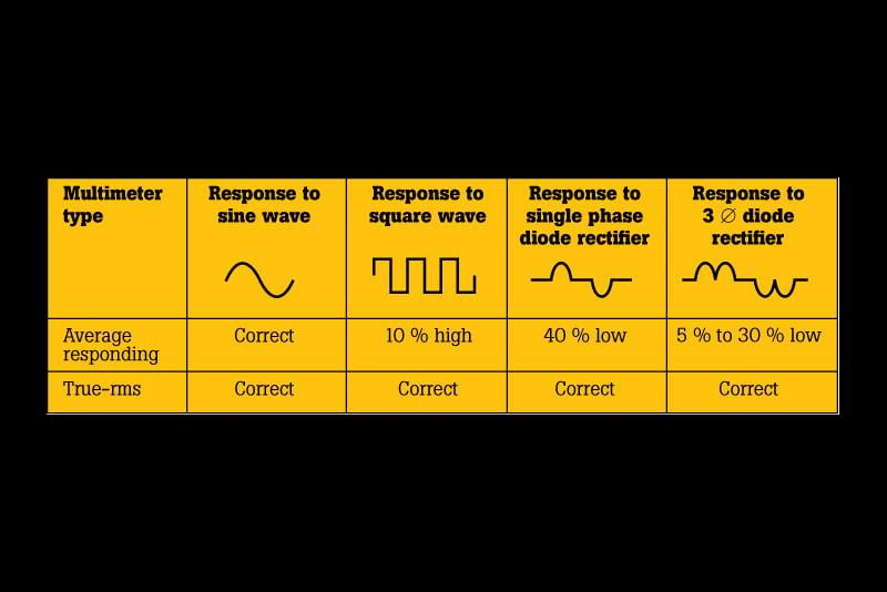
And there are measurement errors... The power reading from a Solar Charge controller may be off by 5% to 10% (usually high?).
If you have a volt meter that is 2% accurate and a current meter that is 2% accurate, the VA measurement may be 4% accurate. Let alone if measuring AC Power with simple meters, you cannot measure the phase angle (you get VA instead of Watts).
How does this matter? Generally you want VA values for wiring, circuit breakers, Transformers, AC Inverter, Genset ratings. It is the "current" that usually matters here (I^2R losses, circulating current, etc.). So your standard meters work well here.
For Power--That matters (mostly) for how much the AC inverter draws from the DC Bus, fuel flow on Genset, etc.
Most "consumer" grade inverters and generators are rated to max Watts where Watts=VA ratings. So battery sizing, solar array sizing, fuel flow are more accurate with "Power" numbers (i.e., if you assume your loads are, on average" 0.80 or 80% PF, the Power will only be 80% of the VA measurements).
Many commercial generators are rated base on 80% Power Factor. And I have seen small UPS System (uninterruptible power supplies for desktop computers) rated on VA output. (large VA rating gives big marketing number on box. "Smaller" Wattage draw gives longer runtime on very small backup battery).
As an Example, APC (a good UPS brand):
https://www.amazon.com/APC-Battery-Protector-Back-UPS-BE600M1/dp/B01FWAZEIU600VA / 330W battery backup power supplyThis assumes the loads are:- Power Factor = 0.55 = 55% power factor
I have seen CFL (compact florescent lamps) with PF listed (something like 0.55 as I recall on some). A standard filament bulb is 1.0 PF (pure resistive).
And there are Linear and non-Linear AC loads.
A induction motor is a "linear" load. The current lags the voltage by xx degrees. And can be corrected by adding a capacitor (cap+inductor) to correct to PF~0.90 (correcting to 1.0 PF has other issues). This is done by large utility customers, such as oil refineries. This not only helps keep wiring/transformer costs down, it saves them money (on large customers, utilities can, and do, charge for kVAH not kWH--There are more details here too).
For homes, utilities (currently) charge for kWH, no kVA) although that can change... Modern digital utility meters (I would guess) have the ability to measure PF and bill on kVA.
So--You are correct... The power factor does have billing implications and system design implications too.
An induction motor that draws 10 amps @ 120 VAC with a 0.8 PF:- 10 amps * 120 VAC = 1,200 VA
- 10 amps * 120 VAC * 0.8 PF = 960 Watts
Note there are lots of "devices" out there that claim to save you energy/etc... They are (from what I know) mostly just a "motor run" type capacitor that is added to your home wiring.
https://www.amazon.com/s?k=miracle+watt+energy+saver
They can bring poor power factor to better power factor... But for typical home that does not change billing/energy usage (again, this is done for oil refineries, but they are sized for each motor--Not just plugged into the mains. In theory, too big of correction can even make -0.8 become +0.8 (capacitive) PF--Stills subject to utility surcharges (for industrial customers). Utilities do have capacitor banks spread around their service area that can be turned on or off to "fix their power factor". Typically turned on in summer with heavy water pumping and A/C usage.
Reading the specifications can even give you a bit of a laugh--When Marketing Speak hits Engineering reality:
https://www.amazon.com/Energy-Saving-Correction-Protection-Service/dp/B00338ZO0MQuestion:I am wanting to decrease spikes from a/c units starting so that solar inverter can keep up. one versus multiple soft-starts is better. will this work?Answer:this product is to get your available power closest to a power factor of zeroBy Steve Sack on December 17, 2020
Phase Angle (Current to Voltage) of zero degrees, but PF = 1.0 (again, go for 0.90 maximum correction for "reasons").
A PF correction capacitor works with Induction Motors. It does not work with non-linear AC to DC power supplies, gas discharge lighting, etc.
What will the AC inverter report? 10 Amps RMS, or 8 amps "power (I.e., 1,200 "Watts" or 960 Watts)... I have not measured (I am not in solar business), so I do not know. I would guess it would report "960 Watts" because that is what is "useful" for solar harvest/battery bank numbers (i.e., on the DC side, working with Watt*Hours of harvest/battery storage/etc.).
A Kill-a-Watt type meter can be "good enough" to measure your loads and estimate the total system loads. Using PF=0.8 is probably good enough for a mixed system design.
If you were lighting a warehouse with fluorescent Lamps--You may need to design the branch circuits at 0.55 PF and double check the AC inverter's ratings (i.e., typically Watts max = VA Max) where a 4,000 Watt inverter = 4,000 VA max and:- 4,000 VA * 0.55 "poor" CFL PF = 2,200 Watts to power lighting
-BillNear San Francisco California: 3.5kWatt Grid Tied Solar power system+small backup genset -
oh no, I thought I had it on grounding, but now I'm slightly confused again!
In my notes I've essentially said if the inverter AC output is isolated from the DC input, then the battery system can be left 'floating' with a breaker on the positive and negative line, and not being grounded. And this is preferable for best safety. Your most recent message indicates that even in this case, the preferable course of action is to bond the negative battery bus to local metal. Is that correct? Would the local metal not also be connected to the main ground for safety purposes, and therefore make the system no longer floating?
I've said that if the system isn't isolated, then you we should ground reference the battery bank to the same ground as the AC system (which would also be bonded to AC neutral). And in this case only a fuse in the positive line is required.
Thanks for all the tips on power factor. It all makes sense now! Seems the big problem is current, so if the power factor can be reduced, then for the same power, the current in the line will be lower, which is a good thing. I will check our wire ratings, and inverter ratings, to check that we've taken into account the power factor, and go through my old notes to add these.
Going back to sizing systems, my colleague was confused about this site, where they say that the DC power input from solar panels should be larger than the AC power output.https://help.helioscope.com/article/248-understanding-dc-ac-ratio
The inverter will have a max PV DC input power rating, though this is less than the continuous AC power output. For example: rating https://www.sunsynk.org/8kw-hybrid-inverter
This makes sense to me because most of the time the solar won't be producing its peak power. Solar panels are cheap, so it is best to have more panels such that on average they are able to provide the continuous load that the inverter can manage. At the times that the solar is producing its 'peak' where does the energy go? I guess some could go towards charging the batteries (this is a combined solar inverter charger), and the rest is lost as heat?
Hopefully I will run out of questions for you soon! It's like a wikipedia research chain -- never ending! Thanks again for your help! -
First, the AC output is (most of the time) only "isolated" from the DC input if the AC inverter is:
- PSW or TSW type inverter almost always isolated (transformer isolated AC output).
- MSW type inverter--Almost always not isolated with respect to DC input (will smoke if AC output and DC input have ground references on their return cable).
- Smaller AC gensets and AC inverters below ~3,500 Watts typically have a floating AC output
- Larger AC gensets and AC inverters above ~3,500 Watts typically have their "Neutral/White Wire" ground referenced at the genset/inverter (to chassis/metal frame ground point).
- Gensets and Inverters with AC Neutral+Ground bond can usually have the N+G bond lifted if needed.
The big issue is if you have "one circuit' or multiple circuits. For example (made up numbers), a DC power system--You have 200 Amp circuit for the AC inverter, a 60 amp circuit for the Solar Charge controller, and a 5 amp circuit for a dome light (or similar).
If you Ground the Negative (Return) bus to chassis/home/plumbing/etc. ground (ground rod or not), this ground referenced system only needs fuses/breaker on the + (HOT) leads:- 200 Amp + Breaker to inverter
- 60 Amp + Breaker to charger
- 5 Amp + Breaker to dome light
- 200 Amp + Breaker
- 200 Amp - Breaker
- 60 Amp + Breaker
- 60 Amps - Breaker
- 5 Amp + Breaker
- 5 Amp - Breaker
If there is a second fault on the - 200 amp cable--That is OK, because it will pop the + 200 amp protective device.
The "gotcha" happens there is a + 200 Amp ground fault, and later there is a - 5 amp short to ground. With only + breakers, that mean the - 5 amp wire needs to "trip" the + 200 Amp breaker--In most cases, the - 5 amp cable is going to fuse/catch fire/etc.
If you have Breakers on both + and - leads, then if there is (for example) a 200 Amp fault to ground, the two 5 amp breakers/fuses on the + & - leads will protect those leads from over current/catching fire because the 5 amp fuses/breakers will trip.
If you only have one or two circuits--Two breakers/fuses is not a huge additional cost... If you have multiple branch circuits of different capacity ratings, then ground referencing the DC bus will let you use 1/2 the number of fuses/breakers.
There are times to float power sources--Boats are an example where you can have electrolysis/corrosion (say the propellor shaft is energize with respect to the metal hull--The corrosion can be very quick and ruin bearings, shafts, props, etc.).
There can be other reasons too... If you are building electrical equipment in a factory... An isolation transformer is used to protect the technician from a shock while assembling and testing the device. And then in final inspection, a High-Pot test (1,800 VAC between AC wring and chassis ground) is performed.
The reason for DC and AC neutral+ground bonding is the same for both (reduce use of double fuses/breaker per circuit). And is the generally accepted solution unless you have specific reason not to do the N+G bonding.
You can get into "weird" configurations... Say you have your DC+AC power system and then wire to a well pump or Amplifhiers for a band on a state... You want to carry that "safety ground" from the DC+AC power shed/trailer/etc. to the point of use (pump, stage, etc.).
There have been some bad accidents where (for example) the AC amplifier equipment has a "grounding/Hot/Neutral" wiring issue and the Microphone+Stand become energized (older equipment (tube based?) relied on polarized plugs--Hot+Neutral)... The Audio ground was supposed to be connected to Neutral, but AC wiring was reversed and was connected to 120 VAC instead). The person on stage grabbed the microphone stand and was shocked because the metal stage was grounded (or at least was a "soft ground").
Following conventions (NEC, etc.) allows many different folks (mfg., electricians, etc.) to do their "piece of the job" and when all is connected together, you have a "safe" installation.
If you do something "different", you can become responsible for everything that is connected and the people that may work on the equipment. More or less, you need to think of any "dumb thing" that a person could do, and make sure that the failure(s) are "safe failures".
Tying AC and DC grounds together for your off grid power system is usually the way to go... The common ground pretty much ensures that if there is a DC HOT to ground short or an AC HOT to ground short, either fault will trip the upstream breaker/fuse and ensure that a "piece of metal" becomes Hot with +48 VDC (battery bus) or +120 VAC with AC power.
If you are really interested in how engineers can do things (I don't recommend) and make them "Code". This was specifically regarding "floating" DC power/battery bus/Solar Panels to lessen the chances of "Arc Faults" (sustained arcs on solar panel wiring). It is a long (and boring?) discussion--But it was directly addressing floating DC power in an AC+DC off grid solar power system:
https://forum.solar-electric.com/discussion/comment/416630#Comment_416630
Regarding "...my colleague was confused about this site, where they say that the DC power input from solar panels should be larger than the AC power output..."... I have not had time to read the link in detail--But many times we use "rules of thumbs" to make quick sizing of "back of the envelope" calculations/system design.
The battery bank is the "heart" of the system. The battery bank supplies all loads (true at night), and accepts charging current (as available).
I can say the solar array has to be at least (or greater rating) vs the AC inverter. This is not for "functional" reasons (AC inverter will work without zero solar power at night)... But just trying to get people to understand that large AC loads (and DC loads), also need a large battery bank and a large solar array to recharge that battery bank the next sunny day.
There are AC inverters that can run without a battery bank (add later)... In that case, the Array has to be rated larger Wattage than the AC inverter's planned AC loads...
I.e., if you have a 1,000 Watt AC load, then the solar array needs to supply >> 1,000 Watts to the inverter (i.e., 1,000 Watts at noon and full sun... But if you want 1,000 Watt load in the morning or evening when the array is outputting 30% of harvest because of sun angle, some clouds, etc.--Then you need a much larger array).
While you can get a rough/quick sizing (is this going to be a 500 Watt system or a 5,000 Watt system)--Understanding your loads (peak loads in Watts, overall energy usage per day in Watt*Hours) and your expectations (no backup genset use in winter, turn off most loads in winter, etc.)... Then design for those needs---Need to do that at some point here.
Designing to rules of thumbs is just the beginning of setting expectations.
You have a DC battery bus... Battery supplies current when needed, accepts charging current when available. This is just like the electrical system on a vehicle. Battery supplies power when the engine is off. Engine alternator supplies power/current to loads and recharges battery when running. During idling, the loads (lights, heater, radio, heated seats, etc.) may draw more power than the alternator can supply while at the stop light. The battery is really what sets the battery bus voltage (10.5 dead to 14.8 volts charging). The loads draw what they need, and the charging sources supply lots of current if the battery is below 13.6 volts, and cut back if the battery is over 14.4 volts (vehicle numbers).
There are lots of variables here... Works best if we focus on what you need to be successful with your project (the power system supplies the energy you need for a reasonable cost).
-BillNear San Francisco California: 3.5kWatt Grid Tied Solar power system+small backup genset
Categories
- All Categories
- 233 Forum & Website
- 140 Solar Forum News and Announcements
- 1.3K Solar News, Reviews, & Product Announcements
- 181 Solar Information links & sources, event announcements
- 895 Solar Product Reviews & Opinions
- 252 Solar Skeptics, Hype, & Scams Corner
- 22.5K Solar Electric Power, Wind Power & Balance of System
- 3.5K General Solar Power Topics
- 6.7K Solar Beginners Corner
- 1K PV Installers Forum - NEC, Wiring, Installation
- 2.1K Advanced Solar Electric Technical Forum
- 5.6K Off Grid Solar & Battery Systems
- 428 Caravan, Recreational Vehicle, and Marine Power Systems
- 1.1K Grid Tie and Grid Interactive Systems
- 656 Solar Water Pumping
- 816 Wind Power Generation
- 621 Energy Use & Conservation
- 623 Discussion Forums/Café
- 316 In the Weeds--Member's Choice
- 74 Construction
- 125 New Battery Technologies
- 108 Old Battery Tech Discussions
- 3.8K Solar News - Automatic Feed
- 3.8K Solar Energy News RSS Feed