Help with 12v wiring diagram

concin
Registered Users Posts: 1 ✭
Anyone with knowledge able to tell me how this looks from an electrical standpoint. Hoping to not start any fires.  Tried to draw it out as neat as possible.
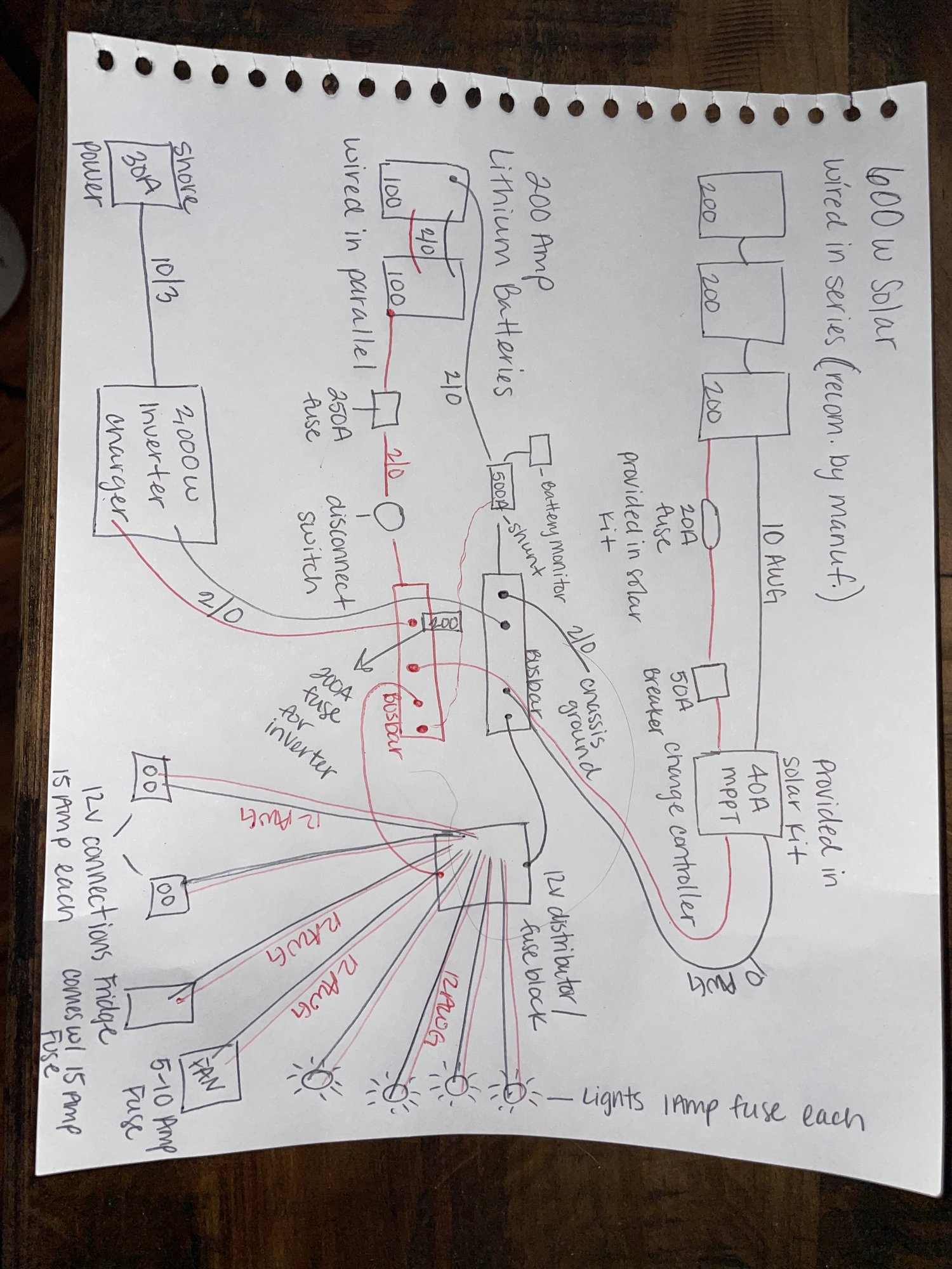
Tried to draw it out as neat as possible. Comments
-
I'm probably no help in figuring out your circuit, but it might get more responses if the images were edited to be in landscape so people don't have to turn their heads sideways to look at it closely. Just a thought.

Good drawings, btw! -
OK... A few questions/comments.
The solar panels have Voc/Vmp/Isc/Imp ratings... What are those (if Voc is "too high", it can over volt the solar charge controller).
What is the Vpanel-input max voltage for your MPPT charge controller (typically 100 or 140-150 VDC--Depending on brand/model).
Where do you plan on camping? Minimum ambient temperature(s)? The Voc-array voltage rises as temperatures fall. If you will be in sever sub zero (F) temperatures, the array voltage and exceed the Solar MPPT controller's maximum input voltage.
Depending on the solar panel(s) Isc (short circuit current)--You probably do not need any fuses on 10 AWG cable at all (good for 30 Amps per NEC). I do not really like multiple fuses/breakers in series.... Breaker and Fuses are made to be "unreliable"--I.e., you want them to trip if too much current--And that can leave you hunting down which tripped, and for fuses, having a spare to replace.
If you just go with a 30 amp breaker--You have your nice on/off switch for power cycling/maintenance. And you do not need to carry replacement fuse(s) with you.
I guess this is a van--So the Panels to MPPT controller are pretty close (not much voltage drop issue). Typically design for 1% to 3% voltage drop.
For charge controller to battery bank/bus... You want short heavy cabling to keep voltage drop down to 0.05 to 0.10 volts maximum for a 12 volt battery bus. You want the charge controller to accurately measure/control the battery bus/charging voltage for optimum charging. So need that cable run distance to figure out the voltage drop and what AWG to use. 10 AWG is a bit "light" for 40 Amps (using NEC chart):
https://lugsdirect.com/WireCurrentAmpacitiesNEC-Table-301-16.htm (simplified chart)
You will need a circuit breaker (or fuse) from battery bus to charge controller to protect the charge controller wiring from over current/short circuits. Your charge controller is rated for 40 Amp max output... For the battery charging wiring/circuits, I like to derate by 1.25 times (or 1/0.80) to keep wiring cool and not false trip fuses and breakers (in North America, most breakers and fuses should trip at 100%+ of rated current, and not trip at 80% or less current):- 40 amps * 1.25 NEC continuous current derating = 50 Amp suggested minimum branch circuit / breaker rating for 40 amp solar charge controller circuit
You have tied the Battery Negative Bus bar to your RV's chassis ground--That is correct (heavy sheet metal, chassis, etc.). That way you only need fuses/breakers in the Positive (hot) DC leads (floating power supplies really should have two breakers, one in each power lead for various reasons).
For your DC power connections to your lighting... You may be "over kill" here... For example say you use 14 AWG cabling which is rated for 15 Amps. you can run 14 AWG to your "switch panel" (if you have one) and then 14 AWG to each of the lights. Or you can run 8 amp breaker/fuse to switch panel/lights on 16 AWG cable... The fuses/breakers are there to protect your wiring from short circuits. So sizing the over current protective device to your wiring is typical (for example, you can always use 8 amp breaker on 14 AWG wiring--Over sizing wire to reduce voltage drop is common for 12 VDC circuits).
You should have a circuit breaker for Inverter's DC power cable too. Both to protect wiring, and to have a handy on/off switch for the inverter (AC inverter typically draw some power--And if you park the RV for winter months, no sun/snow on panels, the AC inverter can take your battery bank dead).- 2,000 Watt inverter * 1/0.85 inverter eff * 1/10.5 volts battery cutoff = 224 Amp minimum branch circuit breaker/wire rating (if you plan on using all 2,000 watts).
Separate AC inverter DC power switch and MPPT solar charge controller power switch--Allows you to disconnect the inverter and keep a few DC circuits alive with solar charging (alarm, cell based monitoring, etc.) when parked.
Regarding the parallel connected battery bank... You probably have it connected correctly for parallel... But just to be clear, here is an explanation on how to do it "right":
http://www.smartgauge.co.uk/batt_con.html
That is a first pass look at your system.
-BillNear San Francisco California: 3.5kWatt Grid Tied Solar power system+small backup genset

Categories
- All Categories
- 233 Forum & Website
- 140 Solar Forum News and Announcements
- 1.3K Solar News, Reviews, & Product Announcements
- 181 Solar Information links & sources, event announcements
- 895 Solar Product Reviews & Opinions
- 252 Solar Skeptics, Hype, & Scams Corner
- 22.5K Solar Electric Power, Wind Power & Balance of System
- 3.5K General Solar Power Topics
- 6.7K Solar Beginners Corner
- 1K PV Installers Forum - NEC, Wiring, Installation
- 2.1K Advanced Solar Electric Technical Forum
- 5.6K Off Grid Solar & Battery Systems
- 428 Caravan, Recreational Vehicle, and Marine Power Systems
- 1.1K Grid Tie and Grid Interactive Systems
- 656 Solar Water Pumping
- 816 Wind Power Generation
- 621 Energy Use & Conservation
- 623 Discussion Forums/Café
- 316 In the Weeds--Member's Choice
- 74 Construction
- 125 New Battery Technologies
- 108 Old Battery Tech Discussions
- 3.8K Solar News - Automatic Feed
- 3.8K Solar Energy News RSS Feed