Building a Wind Farm

Hey guys, If I am building small wind farm with storage with, what is the best configuration from the following scenarios?
Scenario I [10 wind turbines - 3 phase AC, 2kW, and 48V output at full load]:
Each turbine having its own rectifier/charge controller -> Central Battery -> Central Inverter -> Load
Combining all the turbine output to a single rectifier/charge controller (is this even possible, and do such charge controllers exist? I am assuming something with MPPT) -> Central Battery -> Central Inverter -> Load
Scenario II [10 Wind turbines - DC, 2kW, 48V at full load]:
Each turbine having its own DC-DC optimizer (to optimize for the battery input) -> Central Battery -> Central Inverter -> Load
Combining all turbine output to a single DC-DC optimizer -> Central Battery -> Central Inverter -? Load
Are there any other ways to do this? Thanks!
Comments
-
Can I ask what your zip code is?
How high are the wind turbine towers?
The main difference between Scenario #1 and Scenario #2 is ... 3 power wires from the tower vs 2 power wires, respectively
If you want to do MPPT then you cannot combine the raw outputs of the 10 PMA's or PMG's.
It is best to have one MPPT Channel per Wind Turbine and then combine the outputs of the CC into the battery bank
How many kWhrs will you loads need per day?
What happens if there is little or no wind?
You did not mention the Load Dump = Hot Water ?
Battery Bank - voltage and size? -
Thank you! this is actually a research that will be done in a lab environment, and I am trying to figure out the best configuration to connect them to create a schematic that will work better in terms of output performance and ease of installation!mvas said:Can I ask what your zip code is?
How high are the wind turbine towers?
The main difference between Scenario #1 and Scenario #2 is ... 3 power wires from the tower vs 2 power wires, respectively
If you want to do MPPT then you cannot combine the raw outputs of the 10 PMA's or PMG's.
It is best to have one MPPT Channel per Wind Turbine and then combine the outputs of the CC into the battery bank
How many kWhrs will you loads need per day?
What happens if there is little or no wind?
You did not mention the Load Dump = Hot Water ?
Battery Bank - voltage and size?
Also, I was referring to this post (https://forum.solar-electric.com/discussion/354405/multiple-wind-turbine-3-phase-to-load-10kw-240v-home) but did not get a concrete answer. Thanks! -
Assuming nearly identical PMA's, Rotors and Tails
FWB = Full Wave Bridge
My first choice is ...
For best performance - connect each PMA to its own MPPT channel for maximum watts
Each PMA is then optimized for the maximum watts that it can generate.
You will need 10 MPPT Channels = very expensive
My second choice would be ...
Connect many PMA FWB outputs in SERIES into one MPPT Channel
Why?
If a PMA is a "Voltage Source", then they are typically connected in series.
I think, the PMA's will fairly share the total load near the MPPT point of each PMA
How many PMA's can be connected in series ( Max Volts ) into one MPPT Channel?
Some of the PMA FWB's must "float" at higher voltages
Fewer MPPT Channels = less expensive
My third choice would be ...
Connect many PMA FWB outputs in PARALLEL into one MPPT channel ?
How well will your PMA's share the amps?
The PMA with the highest voltage, will bear the most ( or worst case all ) of the load.
The PMA with the lowest voltage, will bear the least ( or worst case none ) of the load.
How many PMA's can be connected in parallel ( Max Amps ) into one MPPT Channel?
Every PMA can have one leg of thr FWB grounded
Fewer MPPT Channels = less expensive
-
Thank you very much for your detailed answer, I will take sometime to digest it and understand it!mvas said:Assuming nearly identical PMA's, Rotors and Tails
FWB = Full Wave Bridge
My first choice is ...
For best performance - connect each PMA to its own MPPT channel for maximum watts
Each PMA is then optimized for the maximum watts that it can generate.
You will need 10 MPPT Channels = very expensive
My second choice would be ...
Connect many PMA FWB outputs in SERIES into one MPPT Channel
Why?
If a PMA is a "Voltage Source", then they are typically connected in series.
I think, the PMA's will fairly share the total load near the MPPT point of each PMA
How many PMA's can be connected in series ( Max Volts ) into one MPPT Channel?
Some of the PMA FWB's must "float" at higher voltages
Fewer MPPT Channels = less expensive
My third choice would be ...
Connect many PMA FWB outputs in PARALLEL into one MPPT channel ?
How well will your PMA's share the amps?
The PMA with the highest voltage, will bear the most ( or worst case all ) of the load.
The PMA with the lowest voltage, will bear the least ( or worst case none ) of the load.
How many PMA's can be connected in parallel ( Max Amps ) into one MPPT Channel?
Every PMA can have one leg of thr FWB grounded
Fewer MPPT Channels = less expensive")
-
Hi,
I have a small wind farm, 3off 3.7m (12footers) diameter, HAWT.
The stator coils are wound for 3 phase at 48v for Charging batteries.
They are a Hugh Piggott design, he has been designing making small very efficient, simple, robust and very cost effective, (up to to 5m diameter), wind turbines for over 45 years. see his books for real data, …….
http://scoraigwind.co.uk/all-of-the-books-by-hugh-how-to-get-them/
Our HAWT have a tail arrangement that automatically turns them out of extreme gusts, and moderates the turbines output.
We therefor say that for a good HAWT we rate 3.7m diameter at a consistent 1kW, yes I have seen 3kW for a brief second before self control takes over.
What I am about to say is empirical evidence and a real case scenario.
Firstly ratings, i see so many Chinese manufactured small HAWT saying they produce 3kW for 3.7m diameter. Yes in a hurricane and last about 12 months before they self destruct. I know because i have tested and selected Chinese brands and dismissed just about all of them.
Two ways of clamping a HAWT, Using a GTI with MPPT that is direct connected to a utilities or Mini Grid. Don't need huge thick cables. Or , Using the clamping down effect of a battery bank, and for 3off HAWT's I would recommend no smaller that 48v 1000ah.
Each of my turbines is independently connected, parrelled, to the battery bank, however you will need a diversion control on the battery bank for when the battery is full and the energy from the turbine is not being used. For this I have 8kW of air resistors, see Hugh's web site for exact details, I also have 7kW of underfloor heating, water heating, etc.
I have 4off diversion controllers, Morningstar Tristar PWM 45's that are independently connected, parrelled, on the battery bank these 4 regulate the battery bank voltage and dump/divert excess voltage. We don not want to overcharge and damage the battery bank.
All 4 of these PWM Tristars are set at the same chagrining regime, but each will do its own thing. However when one of the 45's controllers are maxed out the next will step in and so on. The Tristar never fails its robust and very hardy it gets to 2kW of dumping, maxes out, but carries on and the next takes over. Hugh loves his Tristars and so do I, in this day and age a dam fine bit of gear.
The above paragraph freaks most armchair folk, but in real case scenarios it is a fantastic arrangement.
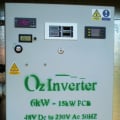
I have a 6kW -15kw OzInverter that runs our 240vac Mini grid and it uses the 48v battery, however, another 12kW of PV is GTI connected to our created Mini Grid and on non windy days can back charge to the battery bank, (the OzInverter is a H Bridge design).
My Opinion, with a battery bank arrangement their are many variables and the cable sizes can be expensive.
Wind each stator HAWT for a high voltage, see Hugh's book, and GTI them to a 240vac/120vac Grid, for this the only good GTI for this was the SMA Windy Boy, and now the High voltage Midnite MPPT but you will need to match the tracking points.
Remember each HAWT needs clamping without a load it will go supersonic and disintegrate.
Allow 2 days for each every year for servicing and re-balancing, YES is a wild horse stuck up on top of a pole kicking the crap out of the mast.
Cost of making mine is now $1200 each.
The below photo, …. I am limited to 40ft 12m high towers as I am in a military low fly zone, but have good continuse South westerly wind.
I now install PV static arrays, its cheaper and more cost-effective that HAWT's, especially as nowadays the latest PV panels have a good ambient light output. PV is just there and no moving parts to worry about.
If you want to get real tech on HAWT then see these guys at ……. https://www.fieldlines.com/
Everything is possible, just give me Time.
The OzInverter man. Normandy France.
3off Hugh P's 3.7m dia wind turbines, (12 years running). ... 5kW PV on 3 Trackers, (8 years) .... 14kW PV AC coupled using Used/second hand GTI's, on my OzInverter created Grid, and back charging with the AC Coupling and OzInverter to my 48v 1300ah batteries.
-
Are you using any MPPT Controllers between the PMA's and the Battery?clockmanfran said:Hi,
I have a small wind farm, 3off 3.7m (12footers) diameter, HAWT.
The stator coils are wound for 3 phase at 48v for Charging batteries.
They are a Hugh Piggott design, he has been designing making small very efficient, simple, robust and very cost effective, (up to to 5m diameter), wind turbines for over 45 years. see his books for real data, …….
It appears that you are not using any MPPT controllers.
If the goal is to maximize Watts Output from the PMA's, then wouldn't an MPPT controller be a required?
You have simply connected all of your FWB's in parallel at the battery bank
and then you regulate the battery voltage via a Diversion Load.
Yes, it is very common to connect the FWB Output from many PMA's, into a single battery pack,
but that does not produce Maximum Watts
Which set of "Equ / Absorb / Float Voltages" and "Time Until Float" did you pick and why?
Set #1: E=15.2v, A=14.9v, F=14.7v, T=4hrs
Set #2: E=15.0v, A=14.7v, F=14.5v, T=4hrs
Set #3: E=14.8v, A=14.5v, F=14.3v, T=4hrs
Set #4: E=14.6v, A=14.3v, F=14.1v, T=4hrs
Set #5: E=14.4v, A=14.1v, F=13.9v, T=4hrs
Set #6: E=14.2v, A=13.9v, F=13.7v, T=3hrs
Set #7: E=14.0v, A=13.7v, F=13.5v, T=3hrs
It seems rather arbitrary that ...
1) The EQ voltage is always 0.3 volts higher than Absorb Voltage
2) The Float Voltage is always 0.2 volts lower than Absorb Voltage
For a FLA Battery Bank ...
a) First Bulk Charge until 14.8v - 14.9v ( 14.7v is too low )
b) Then Absorb Charge at 14.8v - 14.9v
c) Finally Float Charge at 13.3v - 13.4v
I don't see how this is possible with any Parameter Set ( 1 - 7 ) from above.
-
Many MPPT Wind Controllers use the raw 3-Phase AC inputs from the PMA to determine the RPM's of the shaft.usernamemous said:Hey guys, If I am building small wind farm with storage with, what is the best configuration from the following scenarios?
Scenario I [10 wind turbines - 3 phase AC, 2kW, and 48V output at full load]:
Each turbine having its own rectifier/charge controller -> Central Battery -> Central Inverter -> Load
Combining all the turbine output to a single rectifier/charge controller (is this even possible, and do such charge controllers exist? I am assuming something with MPPT) -> Central Battery -> Central Inverter -> Load
Scenario II [10 Wind turbines - DC, 2kW, 48V at full load]:
Each turbine having its own DC-DC optimizer (to optimize for the battery input) -> Central Battery -> Central Inverter -> Load
Combining all turbine output to a single DC-DC optimizer -> Central Battery -> Central Inverter -? Load
Are there any other ways to do this? Thanks!
The RPM value is then mapped to a Max Watts value in the lookup table.
If this is true for the MPPT controller that you select then you cannot combine multiple PMA's into a single MPPT channel.
If you must connect multiple FWB Outputs into one MPPT Channel then maybe an anemometer signal could be an option?
Some have actually added an extra coil to the PMA to provide true Shaft RPM.
Are you designing your own Wind MPPT controller or are you using an off-the-shelf Wind MPPT controller?
Also, what type of Battery Bank are you using = FLA, AGM, NiFe or Lithium ? -
With wind/solar/anything power related--Details matter.
Is this a full off grid system, backup to grid power, or intended to be a Utility Interactive system?
Do you have/need other sources of power when the wind is not blowing (solar panels, genset, etc.)(?
I suggest looking at a high level view first (what your loads are, what resources you have available--Wind/Solar/etc.).
The questions you keep asking about how to connect X number of wind turbines together is sort placing the cart before the horse.
Like trying to figure out the optimum transmission (automatic, manual, 2/3/4/5/6 speed, hydraulic or electrical, etc.) before knowing what the heck the vehicle is and what it is doing (bus, truck, commute car, back hoe, etc.).
-BillNear San Francisco California: 3.5kWatt Grid Tied Solar power system+small backup genset -
mvas,
I have a motto/saying/mantra, Keep it 'SIMPLE', Make it 'ROBUST' and more importantly Keep things 'COST EFFECTIVE'
MPPT, No not for the wind turbines the voltage is never consistent enough to get true MPPT action as the set points can lag and give scary moments.
On 'fieldline's a few are running Midnite MPPT and have some rough set points, but each HAWT will need exact matching to the MPPT set points. I am not one for making things complicated, hence me using PWM diversion controllers.
At low voltages around the 60v, then the MPPT is not really producing much more watts than a PWM. To truly get more out of a PMA then keep the battery low so you maximises power output, but then watch your battery life.
Yes.
I use marine batteries that are sealed lead acid, because its a far more cost-effective option, we call this Golf cart batteries.
The Tristar controllers have 8 choices of settings and a Custom setting option.
I have 14.45, for bulk/absorb, 13.5 for float, and 15.1 for equalise which I have set for manual turn on as I have turned off the Auto sequence. These voltages vary as the temp compensation steps in depending on the time of the year.
In the real world with renewable energy creation , As Bill says, "details matter".
Everything is possible, just give me Time.
The OzInverter man. Normandy France.
3off Hugh P's 3.7m dia wind turbines, (12 years running). ... 5kW PV on 3 Trackers, (8 years) .... 14kW PV AC coupled using Used/second hand GTI's, on my OzInverter created Grid, and back charging with the AC Coupling and OzInverter to my 48v 1300ah batteries.

Categories
- All Categories
- 233 Forum & Website
- 140 Solar Forum News and Announcements
- 1.3K Solar News, Reviews, & Product Announcements
- 181 Solar Information links & sources, event announcements
- 894 Solar Product Reviews & Opinions
- 252 Solar Skeptics, Hype, & Scams Corner
- 22.5K Solar Electric Power, Wind Power & Balance of System
- 3.5K General Solar Power Topics
- 6.7K Solar Beginners Corner
- 1K PV Installers Forum - NEC, Wiring, Installation
- 2.1K Advanced Solar Electric Technical Forum
- 5.6K Off Grid Solar & Battery Systems
- 428 Caravan, Recreational Vehicle, and Marine Power Systems
- 1.1K Grid Tie and Grid Interactive Systems
- 656 Solar Water Pumping
- 816 Wind Power Generation
- 621 Energy Use & Conservation
- 623 Discussion Forums/Café
- 316 In the Weeds--Member's Choice
- 74 Construction
- 125 New Battery Technologies
- 108 Old Battery Tech Discussions
- 3.8K Solar News - Automatic Feed
- 3.8K Solar Energy News RSS Feed