Motorhome 900 Watt Solar System Installation Diagram and Questions

56Nomad
Registered Users Posts: 7 ✭
Hello all,
I’m putting a solar system on my Class A motor home and would appreciate your thoughts on the best way to go about it.
I’ve purchased the following components:
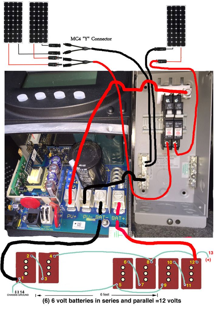
(3) 300W Solar Panels - [Short Circuit Current 8.86 A] [Open Circuit Voltage 45.2 V] Total of 900 watts
(1) OUTBACK FM-80 CHARGE CONTROLLER
(1) MIDNIGHT COMBINER BOX
(2) 15A Breakers
(40) feet of 10 GAUGE SOLAR CABLE
Below is a diagram of how I want to wire it.
Questions:
1. What wire gauge should I use from the COMBINER BOX to the CHARGE CONTROLLER (1 foot apart from each other)?
2. What wire gauge should I use from the CHARGE CONTROLLER to the battery bank ( about a 4 foot run)?
3. Should I just crimp the MC4 connectors to the 10 gauge wire or solder them together?
4. Any other suggestions before I start hooking up wires?
Thanks
I’m putting a solar system on my Class A motor home and would appreciate your thoughts on the best way to go about it.
I’ve purchased the following components:
(3) 300W Solar Panels - [Short Circuit Current 8.86 A] [Open Circuit Voltage 45.2 V] Total of 900 watts
(1) OUTBACK FM-80 CHARGE CONTROLLER
(1) MIDNIGHT COMBINER BOX
(2) 15A Breakers
(40) feet of 10 GAUGE SOLAR CABLE
Below is a diagram of how I want to wire it.
Questions:
1. What wire gauge should I use from the COMBINER BOX to the CHARGE CONTROLLER (1 foot apart from each other)?
2. What wire gauge should I use from the CHARGE CONTROLLER to the battery bank ( about a 4 foot run)?
3. Should I just crimp the MC4 connectors to the 10 gauge wire or solder them together?
4. Any other suggestions before I start hooking up wires?
Thanks

Comments
-
You should use a 3 breaker combiner and not use any "Y" connectors.
Proper Crimp (right tool) is much better/more reliable than soldering.
10 AWG minimum should be fine for the combiner to Outback with three solar panels in parallel (10 AWG is rated for 30 amps minimum).
For charge controller to battery bank... 900 Watts at 11.5 volts minimum typical maximum current would be:- 900 Watts * 1/11.5 volts charging = 78.3 amps typical worst case maximum
- 80 amps * 1.25 NEC derating = 100 Amp minimum rated branch circuit wiring/breaker
You also need to look at the voltage drop. I would suggest a maximum voltage drop of 0.10 volts from charge controller to 12 volt battery bank. Using a generic voltage drop calculator:
http://www.calculator.net/voltage-drop-calculator.html
80 amps and 4 feet one way run, 0.1 volt drop ->
2 AWG:
Voltage drop: 0.10
Voltage drop percentage: 0.69%
Voltage at the end: 14.4
So 2 AWG will meet the 0.1 volt drop at 80 amps of my suggestion.
What is the maximum Load/Charging current you expect through your battery bank? That will help you size the battery interconnect cabling (pretty much like above, use 0.5 volt drop maximum for discharging current).
One last thing to think about--If you are concerned about short circuits, you may want to put a fuse per battery string to protect the interconnect wiring. These fuse holder are pretty nice:
https://www.bluesea.com/products/category/16/72/Fuse%20Blocks/Terminal%20Fuse%20Blocks
And you probably want a large circuit breaker (again rated for maximum load current * 1.25) to protect the wiring to the AC inverter. A circuit breaker for charger to battery bank (100 amp) and inverter to battery bank (xyz amps). And for each + wire that leaves the bank for your other DC loads (breaker are usually nicer long term vs fuses+switches).
-BillNear San Francisco California: 3.5kWatt Grid Tied Solar power system+small backup genset -
Hi Bill,
Thanks for your input. The information you provided is way over my pay grade
However, here is my revised diagram showing what I think you suggested.
1. Do you suggest running (6) separate #10 wires from the roof to the combiner box and of course adding another 15 amp breaker?
Running (6) wires vs (4) wires from roof to the basement compartment will be a more difficult install as I have to run the wires down on an interior wall.
2. These 900 watts of panels is probably more solar than we need for our rig, so my question is how much difference in power delivery is there in wiring it in my original diagram vs this revised diagram? The solar technician at the solar panel dealer recommended the going with the first wiring diagram.
3. What size blade fuse would you recommend between the controller and the battery bank?
-
http://www.smartgauge.co.uk/batt_con.html <--- have a look here and see if you can't fine-tune your battery bank interconnections.
You suggest that 900W PV may be overkill but then I missed the posted amp-hour capacity of the battery type you're using. (typical golf cart batts are +/-230Ah). I will say that a wee bit more panel is ok for the added amperage usable during "bulk" phase charging, not to mention as an assist during grey days. Rule of thumb is a minimum 100 watts PV per 100Ah battery capacity. You may be on the right track after all. -
However, here is my revised diagram showing what I think you suggested.
Yes, you have the basics correct... You may wish to use breakers rather than fuses for things like Charge Controller to Battery bank, AC inverter to Battery bank, and other DC loads (it is easier to shut down stuff when putting the RV away for the season, when working/rebooting controllers/inverter/etc...
For the Outback (and AC inverter)--They do need good ventilation. Do not put these devices in small/sealed hiding holes. They will overheat, possibly thermal shutdown, and not last as long (for every 10C or 18F increase in temperature, the "life" is cut by 1/2.
Also, Charge controllers with fans (like the Outback) are pretty noisy in the middle of the day and passing full current... If fan noise bothers you, move the controller to another part of the vehicle (fans do not run at night for charge controllers, so noise may not be a problem if you are working in the RV during the day). If fan noise will be a problem, you might want to look at a Midnite TS MPPT controller or others that are fanless units (of course, these still need good air circulation).1. Do you suggest running (6) separate #10 wires from the roof to the combiner box and of course adding another 15 amp breaker?
Running (6) wires vs (4) wires from roof to the basement compartment will be a more difficult install as I have to run the wires down on an interior wall.
Yes, 1 breaker for each "serial" panel string is the "correct" way to do this... For a three panel system, the three breakers are almost overkill (the breaker is to stop over current from the other two panels feeding a shorted third panel).
You can put the combiner box near the panels, or near the Outback--Your choice.
You can run a single panel on 20-60 feet (one way run) without much issue... Or you can run short 10 AWG cables to the combiner, and a long pair of heavier (6 awg) cables from the combiner to the Outback for 20-40+ feet. (using voltage drop calcuator for 1% (very good) to 3% maximum (about as much as you would want) voltage drop for 8 amps per panel or 24 amps for 3 panels in parallel running Vmp~30 amps.2. These 900 watts of panels is probably more solar than we need for our rig, so my question is how much difference in power delivery is there in wiring it in my original diagram vs this revised diagram? The solar technician at the solar panel dealer recommended the going with the first wiring diagram.
No meaningful difference--Was just suggesting the 3rd breaker for safety sake. Technically, you can only parallel two of these panels and not need any fuse/breaker in the array.3. What size blade fuse would you recommend between the controller and the battery bank?
From Outback to Battery bank, 100 Amp minimum. The NEC ratings are such that if you run a fuse/breaker at 100% rating, it will eventually trip/blow.
So, the standard is to only run a wire/breaker at 0.85 (85 percent of capacity)... Or 1/0.85 = 1.25x planned usage... I.e.,- 80 amps from charge controller * 1.25 NEC derating = 100 minimum rated branch wiring and fuse/breaker.
http://www.solar-electric.com/installation-parts-and-equipment/midnite.html
-BillNear San Francisco California: 3.5kWatt Grid Tied Solar power system+small backup genset -
This is so much like my system you help me with in July that I'm going to join for some questions.
You asked him for the max load on the battery bank. Wouldn't that be the maximum that the charge controller can put out from the array? In his case, that's 80A due to the max output of the Outback. I'm going with a Midnite Cloud 150 which, I think, has a maximum output of 98A. That x 1.25 = 122.5A max ever. So, in my case for the breaker from the Cloud 150 to the battery terminal block, do I want one with 125A or 150A?
You suggest 56Nomad put those Blue Sea terminal fuses at each of his battery 6-12V pairings. I'll use breakers and like Apples suggested, I'm hooking them up using the Method 3 of Smartgauge' site. Like Nomad,I'm will have 3 pair of batteries. Mine are Lifeline 6CT 300Ah rated. Together, that will make my bank the same 900Ah rated as 56Nomad's. Using Method 3, I'll be bringing 3 Pos 2/0 AWG cables together at a combining lug and continuing with 4/0 on to the main battery terminal lug ( and on to the Magnum 3012 inverter. My question is the same as Nomad will have. Regarding those 3 Pos cables coming from each battery pairing, where does the [breaker in my case] go?
Here's one idea I have that 56Nomad might use, too, if he goes with breakers for the batteries. I have a bulkhead between my battery bank and the other electrical components right on the other side. I could mount a box with DIN rails on the battery side of that wall. I can run (in my case) a 2/0 AWG from each battery pair's empty Pos terminal to one side of a breaker. I can do that three times. From the other side of the breakers, I run short 2/0 to the box's bus bar. From,that bus bar, I take my 4/0 AWG on to the main terminal lug on the other side of the wall, to which is connected another 4/0 to the inverter, a 2/0 to the Cloud comtroller, and other 2/0's to the DC panel, booster start, Aqua Hot and so on. Building this, I can get to the battery breakers easily in the battery bay. What size Amp breakers should I put there? You know the size of my batteries and if he is interested in this, Nomad can tell you his battery specs.
Jerry
What size in Amps of load protection should we put on each battery pair? There's the 14.4A coming from the charger; there's the 80/98A coming from the controller; and there's whatever is the maximum each battery pair can sent out. What do we use? -
Is he going to have any parallel balancing issues with the varying lengths of battery cables?6 250W Renogy panels / Morningstar TriStar MPPT 60 charge controller / 8 Costco CG-2 batteries @ 24V / Samlex PST-1000-24 inverter / Samlex SDC-23 24/12V converter and BG-60 LVD / Midnite Solar boxes, breakers, etc.
-
The Midnite 150 has several different output limits:
http://www.solar-electric.com/inverters-controllers-accessories/chco/misoclchco/misocl/mnclassic.html
Model Number
150
200
Operating Volts Input
150VDC
200VDC
Battery Charge Volts
12-93 Volts
12-93 Volts
Max Current Output
at 25°C (77°F)
96A @ 12V
74A @ 12V
94A @ 24V
70A @ 24V
83A @ 48V
65A @ 48V
De-rated Current
at 40°C (104°F)
80 Amps
66 Amps
For many systems the AC inverter maximum rated output (and 2x surge rating) is the maximum battery bank current (but not always, that is why I ask).
So whatever the maximum is (and many MPPT controllers can program the maximum output current limit)--You want 1.25x minimum output current for fuse and branch circuit wiring rating (note 1/0.85 = 1.25). Of course, for wire size, NEC is quite conservative vs Marine (or other) standards. For longer wire runs, we usually have heavier cabling to keep voltage drop low--Sort runs, we can use smaller cabling (little voltage drop) and we use the max NEC/Marine wire rating instead.
Fuses/breakers are there to protect the wiring/cabling from overheating (and fire). So, if you use 2/0 Rated wiring--NEC and Marine tables would suggest:
https://lugsdirect.com/WireCurrentAmpacitiesNEC-Table-301-16.htm- 145-195 Amps (in conduit, depending on insulation type, ambient temperatures)
http://www.acbsphl.org/Tips_and_hints/ABYC_Wiring.htm- 280 to 330 Amps maximum
For parallel battery strings... In theory, one would think that each battery string would carry 1/3rd of the battery bus current. In practice, I would design each battery string to carry 100% of rated bus current--Prevents false breaker trips and if you have a bad wiring connection or failed open cell--The system will keep running OK until your weekly/monthly inspection finds the problem.
And "ideal batteries" have very little internal resistance. Which means that they have little ability to "equally" share current (loads/charging). What actually "steers" the current is really the resistance in the copper cabling. If one cable path has 1/2 the resistance vs the other path, the lower resistance path will carry much more current.
Battery state of charge does steer current some (each 0.001 higher SG point is ~0.001 volt of increased battery voltage). However, remember that a hot battery has a lower charging voltage--And a hot battery will "accept" more charging current, and get hotter--possibly leading to thermal runaway. Just one of the many ways a battery bank can commit suicide.
-BillNear San Francisco California: 3.5kWatt Grid Tied Solar power system+small backup genset -
In case of two equal 240W panels a single breaker would be enough?BB. said:You should use a 3 breaker combiner and not use any "Y" connectors. -
the breakers are to prevent back flow between each PV should one or 2 decide to run amok and backfeed the other(s) .
You need to connect in the combiner box with plain wires, I think there is an MC4 version that can be ordered.
KID #51B 4s 140W to 24V 900Ah C&D AGM
CL#29032 FW 2126/ 2073/ 2133 175A E-Panel WBjr, 3 x 4s 140W to 24V 900Ah C&D AGM
Cotek ST1500W 24V Inverter,OmniCharge 3024,
2 x Cisco WRT54GL i/c DD-WRT Rtr & Bridge,
Eu3/2/1000i Gens, 1680W & E-Panel/WBjr to come, CL #647 asleep
West Chilcotin, BC, Canada


Categories
- All Categories
- 233 Forum & Website
- 140 Solar Forum News and Announcements
- 1.3K Solar News, Reviews, & Product Announcements
- 181 Solar Information links & sources, event announcements
- 893 Solar Product Reviews & Opinions
- 252 Solar Skeptics, Hype, & Scams Corner
- 22.5K Solar Electric Power, Wind Power & Balance of System
- 3.5K General Solar Power Topics
- 6.7K Solar Beginners Corner
- 1K PV Installers Forum - NEC, Wiring, Installation
- 2.1K Advanced Solar Electric Technical Forum
- 5.6K Off Grid Solar & Battery Systems
- 428 Caravan, Recreational Vehicle, and Marine Power Systems
- 1.1K Grid Tie and Grid Interactive Systems
- 656 Solar Water Pumping
- 816 Wind Power Generation
- 620 Energy Use & Conservation
- 623 Discussion Forums/Café
- 316 In the Weeds--Member's Choice
- 74 Construction
- 125 New Battery Technologies
- 108 Old Battery Tech Discussions
- 3.8K Solar News - Automatic Feed
- 3.8K Solar Energy News RSS Feed