Inverter Earthing

zoneblue
Solar Expert Posts: 1,220 ✭✭✭✭
When it comes to RE system earthing, a DC to AC inverter is unique in that it is exposed to both the AC and DC sides of the system. Thus, attention to its grounding requires special consideration, and any discussion on the subject should proibably seek to clarfiy the meaning of article 690.47 of the NEC 2014.
Other than Bill's prolific writing on the subject, the clearest most succinct article on the internet is this 2007 homepower article, aptly named 'Get Grounded'. It is worth reading, before we go much further.
The point is that, when it comes to earthing the inverter, there are risks in treating an inverter like any other metal box. You can avoid these concerns by using a double insulated inverter such as the Stecas. Europeans like their double insulation, and i have to say im begining to see their point. But for your average inverter, the obvious recourse is to equipment bond the thing to the earth bus in the disconnect and call it good. However we need to look at the range of fault conditions that can occur inside an inverter, which is something like:
a) DC short,
b) AC short,
c) a DC positive to chasis earth fault,
d) an AC hot to chassic earth fault,
e) DC positive to AC hot short.
These are all pretty obscure/unlikely situations, of which manufacturing defects and/or foreign body ingress are possible causes, but should they occur, your earthing system needs to be able to cope with them. (a) and (b) are straight forward, and handled by the circuit protection on the DC side in the case of (a), and by the inverter shutting down for (b).
For (c) and (d), should an inverter develop an earth fault, providing an adequate current path for the resulting fault current is important, as well as ensuring that that current is disconnected correctly.
On the AC side a hot to chasis short will result in the following: In the first instance the chasis becomes live and a shock risk. Immediately after, current will flow through the inverter's EGC, navigate its way through your earth system to find the earth to neutral bond link, thus allowing the current to return to the inverter via the neutral conductor. A few tenths of a second later, the AC breaker in the hot conductor will pop, and/or the inverter will overload and shut down.
The exact same thing occurs on the DC side, with the current returning either via the DC negative to earth bond jumper, or via a ground fault detection and interuption device. The nature of these earth fault currents and the exact path taken is where it gets interesting.
For the AC side, the current that a typical residential off grid inverter can produce is limited to the rated capacity of the inverter, maybe 10 or 20 amps (at 230V). So the EGC needed there is relatively small guage. (However with the higher voltage, there is still a high arc energy and associated fire risk.)
On the DC side, the ability of the circuit breaker which protects the inverter to safely interupt potentially 10,000 or more amps is critically important. The short circuit potential of your battery bank is limited only by the internal resistance of the cells, and the resistance of the associated cabling. If you have a DC GFI, that depends on how it is connected. For example the GFI in the Midnite Classic will high resistance sever the earth, which stops the fault current, but leaves the fault in place.
The question that was on my mind one rainy sunday as i was bolting our VFX to the wall, was, do i equipment bond the inverter to the DC earth bus or the AC earth bus? To make matters more complex the VFX, unilke many/most, has both AC and DC earth terminals. On the other hand cheap and nasty inverters are lucky to have one, usually on the AC side.
Article 690.47(C) (NEC 2011) specifies three alternative earth arrangements for systems involving DC and AC circuits.
Here it is in graphic form:
Attachment not found.
Another diagram, this one from Bluesea, perhaps easier to understand:
Attachment not found.
Source.
The block-diagram-i-ness of these clauses need some intepretation to my mind. NEC method C was more or less what i was i had in mind. However, reading the fine print, that method prohibits a screw terminal connector (in the form of our DC earth bus) between the AC earth bus and the inverter. Some of what they are trying to cater for is:
1. If you run independent DC and AC GECs to the same earth electrode, with only a single single inverter ECG then current passing between the AC and DC earth systems is forced to navigate the single most corosion prone connection, at the stake. Such current occurs in the event of several of our fault types above. You can get around this by crimping or welding the two GECs, but 3 terminal crimps and exothermic welding gear are not necessarily easily accessible.
2. However, you must also factor the differing magnitude of fault currents on the AC and DC sides. If the only earth terminal on the inverter is on the AC side and fits only small guage wire, any earth fault on the DC side will result in hundreds of amps attempting to navigate the AC EGC, fow which it is not rated. This is an ampacity scenario with unhappy consequences.
Thus, the VFX has it right, a large gauge DC earth terminal, and a small guage AC earth terminal. Bonding each to their respective buses, not only provides an appropriate path for the respective fault depending on which side the fault occurs, but when combined with a bond between the AC and DC ground buses, provides a level of redundancy, to doubly make sure that everything is at the same potential. The one remaining concern is that this creates a parallel path in the earth system, a loop if you will. Does a fault on the DC side, take the DC EGC, or the longer AC ECG, AC earth bus, AC/DC bond route. Well, clearly a fault current would take both routes, but with ampacity and resistance being generally proportional, the lower resistance DC would take the larger share.
Which brings us to the sizing of inverter EGCs. What is obvious is that the ampacity of the earth wire should meet the rating of the circuit breaker protecting the current carrying conductors on that side of the inverter. In practice because the EGC only carrys fault currents for brief periods some derating is allowed, often 25 or 30%. However, the code also makes a relationship between the size of the current carrying conductors and the EGC. Again some derating is allowed. I have not seen an explanation of the reason for this ruling, however the paragraph above goes some way to an answer. The bigger the DC EGC the less risk that the AC EGC will carry current beyond its ampacity. But again in practice if you have quality circit protection, the duration of fault currents in your earthing system will be very very brief, and its possible that smaller EGCs are manageable in practice.
Here is a diagram of my adopted solution.
Attachment not found.
Lastly, what happened to fault case (e), you ask? Well thats messy alright, and its a form of earth fault in that the fault current also traverses the earth system. The internal AC hot short, bypasses the AC circuit protection, and yet doesnt source sufficient current to trip the DC side protection. The inverter will detect the high output current, and likely high input voltage, and then shutdown, and the peak fault current is limited to the rated inverter output as with fault type (b). What a cheap inverter with poor output protection might do is another matter altogether.
Anyway hopefully this gets us all thinking a bit more on this topic, and it certainly makes you appreciate those nice prewired solutions that embed so much of this design wisdom, that is otherwise a bit painful to contemplate.
Other than Bill's prolific writing on the subject, the clearest most succinct article on the internet is this 2007 homepower article, aptly named 'Get Grounded'. It is worth reading, before we go much further.
The point is that, when it comes to earthing the inverter, there are risks in treating an inverter like any other metal box. You can avoid these concerns by using a double insulated inverter such as the Stecas. Europeans like their double insulation, and i have to say im begining to see their point. But for your average inverter, the obvious recourse is to equipment bond the thing to the earth bus in the disconnect and call it good. However we need to look at the range of fault conditions that can occur inside an inverter, which is something like:
a) DC short,
b) AC short,
c) a DC positive to chasis earth fault,
d) an AC hot to chassic earth fault,
e) DC positive to AC hot short.
These are all pretty obscure/unlikely situations, of which manufacturing defects and/or foreign body ingress are possible causes, but should they occur, your earthing system needs to be able to cope with them. (a) and (b) are straight forward, and handled by the circuit protection on the DC side in the case of (a), and by the inverter shutting down for (b).
For (c) and (d), should an inverter develop an earth fault, providing an adequate current path for the resulting fault current is important, as well as ensuring that that current is disconnected correctly.
On the AC side a hot to chasis short will result in the following: In the first instance the chasis becomes live and a shock risk. Immediately after, current will flow through the inverter's EGC, navigate its way through your earth system to find the earth to neutral bond link, thus allowing the current to return to the inverter via the neutral conductor. A few tenths of a second later, the AC breaker in the hot conductor will pop, and/or the inverter will overload and shut down.
The exact same thing occurs on the DC side, with the current returning either via the DC negative to earth bond jumper, or via a ground fault detection and interuption device. The nature of these earth fault currents and the exact path taken is where it gets interesting.
For the AC side, the current that a typical residential off grid inverter can produce is limited to the rated capacity of the inverter, maybe 10 or 20 amps (at 230V). So the EGC needed there is relatively small guage. (However with the higher voltage, there is still a high arc energy and associated fire risk.)
On the DC side, the ability of the circuit breaker which protects the inverter to safely interupt potentially 10,000 or more amps is critically important. The short circuit potential of your battery bank is limited only by the internal resistance of the cells, and the resistance of the associated cabling. If you have a DC GFI, that depends on how it is connected. For example the GFI in the Midnite Classic will high resistance sever the earth, which stops the fault current, but leaves the fault in place.
The question that was on my mind one rainy sunday as i was bolting our VFX to the wall, was, do i equipment bond the inverter to the DC earth bus or the AC earth bus? To make matters more complex the VFX, unilke many/most, has both AC and DC earth terminals. On the other hand cheap and nasty inverters are lucky to have one, usually on the AC side.
Article 690.47(C) (NEC 2011) specifies three alternative earth arrangements for systems involving DC and AC circuits.
Source."[Y]ou must bond the dc grounding system to the ac grounding system. Section 690.47(C) specifies three methods for providing that bond.
*Separate and bonded*. Per Section 690.47(C)(1), a separate dc grounding-electrode system can be installed, provided it is bonded to the ac grounding-electrode system, as shown in Option 1 in Figure 2. The ac and dc GECs must be sized based on their respective NEC sections, and the grounding electrodes must be bonded using a conductor no smaller than the larger of the ac or dc GECs. Note that the dc GEC and/or the bonding conductor between the grounding electrodes cannot replace the required EGCs.
Separate and bonded grounding-electrode systems are used on residential and commercial retrofits, as well as large utility-scale systems. A dc grounding electrode, such as a new ground rod or ring, is installed as part of the PV system and connected via a dc GEC to the marked point in the inverter. The dc grounding electrode is then bonded to the premise’s existing ac grounding-electrode system, such as a ground rod or Ufer, or, in large-scale systems, to the newly installed ac grounding electrode on the secondary side of a medium-voltage transformer that is between the inverter and the utility grid.
*Common grounding electrode*. NEC Section 690.47(C)(2) allows for a common grounding electrode (or grounding-electrode system) to serve both the ac and dc systems, as shown in Option 2 in Figure 2. The dc GEC cannot replace the required ac EGC. In the event that the ac grounding electrode is not accessible, the dc GEC can connect directly to the ac GEC per Section 250.64(C)(1), which allows for irreversibly crimped or exothermically welded connections.
This method is widely employed for a variety of PV system types, from residential to utility-scale systems. For example, a ground ring around an inverter and transformer pad can serve as both the ac and the dc grounding electrode. The allowance for connecting to the ac GEC is helpful when the existing grounding electrode is a Ufer. Be aware, however, that if an existing ac grounding electrode is inaccessible, then there may be no way to verify that the resistance to ground is less than or equal to 25 O, as required in Section 250.53(A)(2). In such cases the AHJ may require a supplemental grounding electrode; if so, this must be installed at least 6 feet away from the existing electrode and bonded to it.
*Combined grounding conductor*. A combined grounding conductor can serve as both the dc GEC and the ac EGC, as shown in Option 3, Figure 2. While Section 250.121 specifies that an EGC cannot be used as a GEC, Section 690.47(C)(3) amends this general Code requirement and provides an allowance exclusively for PV systems. On the face of it, installing one conductor instead of two seems like the simplest and least expensive method. In practice, the requirements associated with installing a combined grounding conductor may complicate things.
Since the combined grounding conductor serves two functions—dc GEC and ac EGC—it must be sized according to the function that requires the largest conductor: The size of the ac EGC is determined based on NEC Table 250.122, and the size of the dc GEC is determined based on Section 250.166. Further, the combined conductor must either run unspliced or irreversibly spliced from the inverter to the grounding busbar in the associated ac equipment, which refers to the ac equipment that the ac GEC connects to. As a result, you must crimp pigtails to the combined grounding conductor whenever you need to connect an EGC to any electrical equipment—including disconnect switches, production meters, switchgear and so forth—located between the inverter and the final termination point at the ac GEC. Lastly, all other GEC installation requirements still apply, such as bonding ferrous raceways.
While the option to use a combined grounding conductor is applicable to all PV system types, it is most common on systems that use microinverters with an internal dc system bonding jumper. While the microinverter trunk cable may include an EGC, the grounding conductor connected to the microinverter chassis runs from the PV array to the associated ac equipment, serving as both the dc GEC and the ac EGC
Here it is in graphic form:
Attachment not found.
Another diagram, this one from Bluesea, perhaps easier to understand:
Attachment not found.
Source.
The block-diagram-i-ness of these clauses need some intepretation to my mind. NEC method C was more or less what i was i had in mind. However, reading the fine print, that method prohibits a screw terminal connector (in the form of our DC earth bus) between the AC earth bus and the inverter. Some of what they are trying to cater for is:
1. If you run independent DC and AC GECs to the same earth electrode, with only a single single inverter ECG then current passing between the AC and DC earth systems is forced to navigate the single most corosion prone connection, at the stake. Such current occurs in the event of several of our fault types above. You can get around this by crimping or welding the two GECs, but 3 terminal crimps and exothermic welding gear are not necessarily easily accessible.
2. However, you must also factor the differing magnitude of fault currents on the AC and DC sides. If the only earth terminal on the inverter is on the AC side and fits only small guage wire, any earth fault on the DC side will result in hundreds of amps attempting to navigate the AC EGC, fow which it is not rated. This is an ampacity scenario with unhappy consequences.
Thus, the VFX has it right, a large gauge DC earth terminal, and a small guage AC earth terminal. Bonding each to their respective buses, not only provides an appropriate path for the respective fault depending on which side the fault occurs, but when combined with a bond between the AC and DC ground buses, provides a level of redundancy, to doubly make sure that everything is at the same potential. The one remaining concern is that this creates a parallel path in the earth system, a loop if you will. Does a fault on the DC side, take the DC EGC, or the longer AC ECG, AC earth bus, AC/DC bond route. Well, clearly a fault current would take both routes, but with ampacity and resistance being generally proportional, the lower resistance DC would take the larger share.
Which brings us to the sizing of inverter EGCs. What is obvious is that the ampacity of the earth wire should meet the rating of the circuit breaker protecting the current carrying conductors on that side of the inverter. In practice because the EGC only carrys fault currents for brief periods some derating is allowed, often 25 or 30%. However, the code also makes a relationship between the size of the current carrying conductors and the EGC. Again some derating is allowed. I have not seen an explanation of the reason for this ruling, however the paragraph above goes some way to an answer. The bigger the DC EGC the less risk that the AC EGC will carry current beyond its ampacity. But again in practice if you have quality circit protection, the duration of fault currents in your earthing system will be very very brief, and its possible that smaller EGCs are manageable in practice.
Here is a diagram of my adopted solution.
Attachment not found.
Lastly, what happened to fault case (e), you ask? Well thats messy alright, and its a form of earth fault in that the fault current also traverses the earth system. The internal AC hot short, bypasses the AC circuit protection, and yet doesnt source sufficient current to trip the DC side protection. The inverter will detect the high output current, and likely high input voltage, and then shutdown, and the peak fault current is limited to the rated inverter output as with fault type (b). What a cheap inverter with poor output protection might do is another matter altogether.
Anyway hopefully this gets us all thinking a bit more on this topic, and it certainly makes you appreciate those nice prewired solutions that embed so much of this design wisdom, that is otherwise a bit painful to contemplate.
1.8kWp CSUN, 10kWh AGM, Midnite Classic 150, Outback VFX3024E,
http://zoneblue.org/cms/page.php?view=off-grid-solar
http://zoneblue.org/cms/page.php?view=off-grid-solar
Comments
-
Zoneblue, I have a few comments (Note I dont intend to insult your knowledge level, I have added more detail at times for others who may read this).
First, I think it is important to mention that the homepower article you linked has a serious and dangerous error. The author claims that connected metal parts to earth prevents shocks from faults, which is not true. The connection of equipment to earth is of very minor importance and serves purposes other than providing protection from line to case faults. This is an extremely common belief and problem in the electrical industry. I think this belief persists and is so prevalent largely because of the continued use of the terms "grounding" and "earthing". If I may make a suggestion, that is to refrain from using these terms when discussing providing a low impedance path back to the source (which has nothing to do with the earth whatsoever), and only use them when actually talking about system grounding or equipment earthing. My preferred way do discuss the general topic of grounding, Is to break it up into three different topics: system grounding, providing a low impedance path back to the source to trip a fuse or circuit breaker (bonding), and equipment earthing. It makes sense to break it up into these parts as they are three different things that serve completely different purposes. It drives me crazy when the topic is presented as the homepower author did and lumps everything into one topic and thing - again they are three different things that serve different purposes.
Secondly, some comments on the bulk of your post.
1. As mentioned above, remember system grounding, equipment grounding, and bonding (providing low impedance path back to the source) are different things serving different purposes. Note that 690.47 provides instruction on providing and connecting the grounding electrode system. This is used for system grounding (making a bond between the earth, metal equipment parts, and one of the system conductors) if we have a grounded system, and in both grounded and ungrounded systems, connecting metal parts to earth (which provides equipotential between metal parts and the earth from the effects of capacitance, static, and ground potential rise from a nearby lightning strike - thats all folks, it doesnt do much else). The inverter will typically have nothing to do with the grounding electrode conductor connections - it will have an equipment grounding conductor run with the conductors on the DC side (just like any other piece of utilization equipment) and on the AC side it will have what is called a supply side bonding jumper going to the AC panel and the panel will have a system bonding jumper bonding the neutral (or one of the hot legs if 120V only) to the ground bus and the supply side bonding jumper. I acknowledge that there are theoretically other arrangements as you mentioned such as the combined DC GEC and AC EGC, but I am not aware of any off grid inverters that make or have provisions to make a system bond in them and making your own would not be very practical in most cases due to limited space, wire bending space, terminal listing, etc.. I am not familiar with all brands of inverters so correct me if I am mistaken, but that is my understanding.
2. Note that the NEC requires system grounding on a 120V and 120/240 system. The NEC does not require system grounding for most PV and DC systems. IF you choose to make the DC system grounded, make sure you charge controller isnt already doing it for you and also note that the GEC connection may need to be made at the CC as part of its GFP. Remember, even if the SYSTEM isnt grounded, you still need to bond all the metal parts to the grounding electrode system per 690.47
3. Finally, I feel it is worth mentioning that system grounding (grounded/ungrounded) is a system topology, its not about safety. Both type of systems are used extensively and safely throughout different parts of the world. Each has some advantages and disadvantages. I just think that is important to mention as system grounding is usually lumped together with the other two groundings, and often people hear "ungrounded" and they think danger (I have mentioned in other threads that I think keeping the DC side ungrounded is safer overall, IMO). -
^ Ethan,
How can you say that connectiong metal parts to earth is not protecting anything or of minor importance...
Connecting metal parts to earth prevents voltage/potential form building in metal parts, thus preventing/reducing shocks.
No it doesnt clear a fault, BUT it drains wanton voltage significantly reducing shock risk...
~1.5Kw PV in parallel
Morningstar MPPT-60 controllers (2) in parallel
3 Trojan tr-1275's in parallel 450ah total
Samlex 2,000 watt 12-volt inverter hardwired -
Specifically, the "ground rod" can have as high as 20-25 Ohms resistance (roughly, as I recall, I am not a code guy) to the earth and still be "legal".
120 VAC / 25 ohms = 4.8 amps
This is not enough current to trip a standard 15 amp breaker in the home power panel. In fact, it does very little in this example (other that waste some electricity).
What makes things "safe" is that green wire that connects to every electrical panel, conduit, hot/cold water pipe, natural gas line (inside the house), etc... If there is a short from 15 amps to "something metal" in the house, there is a low enough resistance in the green wire to pop the circuit breaker (instead of "energizing" that sink/etc) reduce the chances of somebody getting "shocked or electrocuted" (because the breaker has been tripped).
-Bill
Near San Francisco California: 3.5kWatt Grid Tied Solar power system+small backup genset -
Specifically, the "ground rod" can have as high as 20-25 Ohms resistance (roughly, as I recall, I am not a code guy) to the earth and still be "legal".
120 VAC / 25 ohms = 4.8 amps
This is not enough current to trip a standard 15 amp breaker in the home power panel. In fact, it does very little in this example (other that waste some electricity).
What makes things "safe" is that green wire that connects to every electrical panel, conduit, hot/cold water pipe, natural gas line (inside the house), etc... If there is a short from 15 amps to "something metal" in the house, there is a low enough resistance in the green wire to pop the circuit breaker (instead of "energizing" that sink/etc) reduce the chances of somebody getting "shocked or electrocuted" (because the breaker has been tripped).
-Bill
Yes 25 ohms is the spec but it can only be tested by having another ground bar to reference, or a ground resistance meter. Since very few people (my offgrid folks do) install a second ground bar it is a hopeful result that the breaker will trip in the failure. Bill, I had 2 more XW systems shut down this winter in lightning from the GFCI in the controllers, not sure what it saved but it still gives me the warm fuzzies when they power back up again."we go where power lines don't" Sierra Nevada mountain area
htps://offgridsolar1.com/
E-mail offgridsolar@sti.net -
Ethan Brush wrote: »The author claims that connected metal parts to earth prevents shocks from faults, which is not true. The connection of equipment to earth is of very minor importance and serves purposes other than providing protection from line to case faults.
The point of the OP is about inverter equipotential bonding, in particular the risk of overheating under-sized EGCs. While youve made your position clear on the grounding to earth topic , and im not in complete disagreement, i would put a couple of things back to you by way of questions.
An electric fence shows how, even with the high resistance of ground electrode to earth connections, that electric shock results between earth ground and a live conductor regardless. And regardless of the exact nature of the surface you are standing on be it rubber boots, wet grass etc. I imagine thats in part due to the high voltage, and in part the high resistance of skin and body tissue, requiring effectively only milliamps to feel and be shocked. Static build up can result in similar 'tingles' and zaps, and thats one way that i read the NECs insistance on grounding to (planet) earth.
Thus, assuming the use of metal chasis appliances, lets face it some things can not be double insulated, stoves, sinks, diswashers, laundry etc, what is actually the effect of standing on the floor of a house, that is at or is not at ground potential? Isnt setting the floor of the house at the same potential as the appliance chasis consistent with equipotential bonding?
OK, earthing as you have said, does for better or worse does radically increase the surface area of material at the potential of one of the current carrying conductors. Theres no argument there. The questions really remain about the validity of the lightning and static issues.(I have mentioned in other threads that I think keeping the DC side ungrounded is safer overall, IMO).
But you havent said why, at least not to my mind, convincingly. Things like GFI, and TL inverters are less reasons than side issues.
1.8kWp CSUN, 10kWh AGM, Midnite Classic 150, Outback VFX3024E,
http://zoneblue.org/cms/page.php?view=off-grid-solar -
^ Ethan,
How can you say that connectiong metal parts to earth is not protecting anything or of minor importance...
Connecting metal parts to earth prevents voltage/potential form building in metal parts, thus preventing/reducing shocks.
No it doesnt clear a fault, BUT it drains wanton voltage significantly reducing shock risk...
Well your explanation sounds good, but.....What is this voltage that is "building up" and where is it coming from? How often to you get shocked by your car or in an airplane? Sure you could have some capacitance or static build up on "stuff" thats not connected to earth, but it will be very small and not noticable the vast majority of times. I have been an electrician for 16 years and worked on all sorts of ungrounded/improperly grounded systems and never experienced a shock from these effects, nor have I heard of such a thing ever happening. I am not saying it cant happend or dont bother earthing metal parts, but to understand the topic of "grounding", one needs to understand what we do and why and that the connection of metal parts to earth is of minor importance and doesnt do much for safety - it is bonding metal together and back to the source that does nearly all the work.Specifically, the "ground rod" can have as high as 20-25 Ohms resistance (roughly, as I recall, I am not a code guy) to the earth and still be "legal".
Ground rods are the only electrode that the NEC mentions a resistance spec for, and basically it says that if one rod isnt 25 ohms or less, drive another one and call it day - that is you dont have to retest the two rod combo, you are done regardless with 2 rods. A little strange perhaps but that is why most electricians will just pound two and skip the resistance check.OK, earthing as you have said, does for better or worse does radically increase the surface area of material at the potential of one of the current carrying conductors. Theres no argument there. The questions really remain about the validity of the lightning and static issues.
I addressed the static issue above. I am just very skeptical about how lightning induced surges would be mitigated by equipment earthing. Say we have a very close lightning strike and the electric field induces a current and voltage on my metal "Stuff" in my house. Assuming all my non current carrying metal parts are properly bonded together, what is the difference in fire and life safety if the metal parts are connected to a rod in the dirt or not? I would have to be contacting the ground for one thing which is quite unlikely unless I am in the basement of an older house that has a dirt floor or a slab without insulation or a vapor barrier. So say I am, well unless I am standing right on top of the grounding electrode, I will still be subject to a high voltage gradient due to the high resistance of the dirt (even if the metal parts are connected to the dirt). Maybe I am not thinking of the right scenario, but I see protection from earthing being extraordinarily rare.
Regarding system grounding, here are my thoughts: First a lot of it comes down to my belief/philosophy that on a macro scale system grounding or not is a type of system design and not specifically about safety. Sure people will debate it like ford vs chevy and people have debated it for decades. It seems that both types of systems have a strong long track record of safe operation. To us in parts of the world where one system is common and the other is not, the other type of system probably seems foreign and irrational to us. Here in the US, there are two major reasons for using grounded systems (besides history/tradition and fear of ungrounded systems), but this is not because of an inherent problem with ungrounded systems, it is simply because utility practices and the grid are designed around grounded systems. The first reason is that we use a bare messenger as the neutral for service drops and often have uninsulated high voltage lines above it. If a high voltage line falls on a service drop, having that conductor grounded at the premise is important because it will help the current get back to its source via the dirt (high voltage can use dirt as an effective fault current path) and trip a utility OCPD thus deactivating the line and bringing all your metal stuff back to around earth potential quickly. Secondly, utilities very often use one transfomer to feed multiple buildings and this would be very dangerous practice to use with ungrounded systems since un-noticed different phase faults in different buildings would cause all sorts of stray current and equipotential issues. So, off grid folks are not served by a utility so these issues are moot. So what is left? Well now its just a game of weighing out the usual disadvantages and advantages of each system type. Grounded systems have the advantage that first faults are detected and dealt with automatically (well maybe not quite with a current limited source like PV, but lets not get into the GFP debate and what the best fault detection system would be). The disadvantage is we have a much greater chance of getting a line to ground shock and line to ground arc blast/flash. I think this is a huge disadvantage for many off grid folks who are always tweaking, tinkering, and adjusting their system while it is active. Further we have lots of exposed terminals on DC stuff like inverter terminals and battery terminals, etc. Consider this: as I said I am an electrician and I have received literally hundreds of line to ground shocks and "welded" some tools form line to case faults. I can only recall getting 2 line to line shocks- its just a lot harder to do. The disadvantage of ungrounded systems is that a first fault can be hard to detect but this often doesnt even matter - a first fault makes it a grounded system now and its not a safety problem if it goes unnoticed or unfixed. The only problem in my mind is if someone is assuming the system is ungrounded and doesnt check and find out there is fault and gets a shock or some arc blast in the eye. Granted, Some may consider this "variability" a huge disadvantage for joe-off-grid fiddling around with his system on the weekend. Personally, I think the ungrounded system is safer for the DC side.
-
Dear Ethan,
Every single day I tool around in my ungrounded cars, whenever I step out and touch the door of the car to close it, ZAP!, theres my shock. The car isint connected to earth, it builds up all this voltage, and I get zapped when my feet connect to ground better than the 4 rubber tires can...
How soon ye forget the oldendays before stuff was grounded and youd get all sorts of shocks in your house...
I understand the point of clearing faults by bonding... but making all metal compents 'zero voltage' (ie to ground potential) IS equally improtant...
--caky
~1.5Kw PV in parallel
Morningstar MPPT-60 controllers (2) in parallel
3 Trojan tr-1275's in parallel 450ah total
Samlex 2,000 watt 12-volt inverter hardwired -
Every single day I tool around in my ungrounded cars, whenever I step out and touch the door of the car to close it, ZAP!, theres my shock. The car isint connected to earth, it builds up all this voltage, and I get zapped when my feet connect to ground better than the 4 rubber tires can...
That is very unfortunate and strange that that happens to you every day. I am sorry you have to live with that.
How soon ye forget the oldendays before stuff was grounded and youd get all sorts of shocks in your house...
I have also never experience this despite having lived and working daily in ungrounded houses, nor have I ever had a client complain of getting static and capacitive shocks. Keep in mind much of the electrical stuff in typical residence does not have a ground prong, and things like wood stoves, metal siding, metal roofing, metal beds, metal doorknobs, etc are no grounded/bonded.
I understand the point of clearing faults by bonding... but making all metal components 'zero voltage' (ie to ground potential) IS equally improtant...
Your are entitled to your opinion, however the statistics and physics do not concur with your assessment.
--caky
[/QUOTE]
-
Ethan Brush wrote: »
That is very unfortunate and strange that that happens to you every day. I am sorry you have to live with that.
I have also never experience this despite having lived and working daily in ungrounded houses, nor have I ever had a client complain of getting static and capacitive shocks. Keep in mind much of the electrical stuff in typical residence does not have a ground prong, and things like wood stoves, metal siding, metal roofing, metal beds, metal doorknobs, etc are no grounded/bonded.
Your are entitled to your opinion, however the statistics and physics do not concur with your assessment.
--caky
[/QUOTE]
Ethan,
YOU are why the NEC exists. Connecting metal to ground is how you drain off wanton voltages. Period. I dont know why this is so hard to understand? Why must it be overcomplicated and go into the realm of voodoo?
Gawl! Anyone who ever got a static shock KNOWS that its because of VOLTAGE going to GROUND (through the PERSON).
Thankfully every place in the USA is grounded.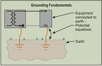
"potential equalized"
Learn
~1.5Kw PV in parallel
Morningstar MPPT-60 controllers (2) in parallel
3 Trojan tr-1275's in parallel 450ah total
Samlex 2,000 watt 12-volt inverter hardwired -
There is a different between "grounding" metal *like in a car" (the battery is ground referenced inside the car) and ground referencing with a metal rod in the round (car battery floating with respect to earth).
Bonding all metal to be "equal potential", as used in North America, allows us to only need to put "over current protective devices" on one lead (the hot lead with respect to ground).
For floating systems, we really need to put pairs of OCPD to prevent excess current flow in both Hot and Return leads (i.e., a floating supply that has a single fault in a light fixture--negative to ground) and then a second short (hot to ground) at the main panel/bus bar--Will cause excessive current to flow in the remote (small gauge negative wiring) in the fixture--And start a fire. With pairs of breakers--Then the return current would trip the breaker for the small gauge wire to the fixture.
The above is why "floating" a battery bank in a large DC power system is problematic. Two shorts in different locations with fusing/breaker only in the positive leads leaves the negative leads vulnerable to unprotected excessive current flow.
Unless, you have a system that would detect/shut down the floating power system on the first fault (this is done for "true" floating systems that have to meet safety requirements).
Ground referencing to earth is important in North American safety--As mentioned above, static discharge, lightning (debatable), and high voltage to low voltage line crosses (and there is the starting of some florescent tube fixtures that need grounded metal chassis to assist the starting of the arc). There are also cathodic protection systems (gas piping, large metal tanks/structures) that are charged to reduce the effects of DC current corrosion of dissimilar metals.
-BillNear San Francisco California: 3.5kWatt Grid Tied Solar power system+small backup genset -
Solar installations have i think one addtional risk factor. In a normal grid connected building, there are many layers of circuit pro, that protect everything downstream, eg:breakers in distribution boards protect sub circuit wiring, the main switchboard breaker protects most of the switchboard itself, then everything between the street and that breaker are protected by pole fuses, from there back to the transformer by the transformer fuses,etc all the way back to the generator.
However PV arrays themselves are not as well protected, and you have the inter-module cabling exposed to wind, weather and wildlife. This wiring is in some ways more vulnerable than load circuits. Even though its current limited the DC arc factor makes it a particular fire risk.
1.8kWp CSUN, 10kWh AGM, Midnite Classic 150, Outback VFX3024E,
http://zoneblue.org/cms/page.php?view=off-grid-solar -
Solar installations have i think one addtional risk factor. In a normal grid connected building, there are many layers of circuit pro, that protect everything downstream, eg:breakers in distribution boards protect sub circuit wiring, the main switchboard breaker protects most of the switchboard itself, then everything between the street and that breaker are protected by pole fuses, from there back to the transformer by the transformer fuses,etc all the way back to the generator.
However PV arrays themselves are not as well protected, and you have the inter-module cabling exposed to wind, weather and wildlife. This wiring is in some ways more vulnerable than load circuits. Even though its current limited the DC arc factor makes it a particular fire risk.
The fire risk and other electrical destruction also extends to everything that comes in to the home from outside. A telephone line, TV antenna, and Sat dish are just as prone and I have seen them take out an inverter. In one case the Inverter failed 3 times before the owner understood. Disconnect, protect, or pray for all these sources during really bad weather."we go where power lines don't" Sierra Nevada mountain area
htps://offgridsolar1.com/
E-mail offgridsolar@sti.net -
There is a different between "grounding" metal *like in a car" (the battery is ground referenced inside the car) and ground referencing with a metal rod in the round (car battery floating with respect to earth).
Bonding all metal to be "equal potential", as used in North America, allows us to only need to put "over current protective devices" on one lead (the hot lead with respect to ground).
For floating systems, we really need to put pairs of OCPD to prevent excess current flow in both Hot and Return leads (i.e., a floating supply that has a single fault in a light fixture--negative to ground) and then a second short (hot to ground) at the main panel/bus bar--Will cause excessive current to flow in the remote (small gauge negative wiring) in the fixture--And start a fire. With pairs of breakers--Then the return current would trip the breaker for the small gauge wire to the fixture.
The above is why "floating" a battery bank in a large DC power system is problematic. Two shorts in different locations with fusing/breaker only in the positive leads leaves the negative leads vulnerable to unprotected excessive current flow.
Unless, you have a system that would detect/shut down the floating power system on the first fault (this is done for "true" floating systems that have to meet safety requirements).
Ground referencing to earth is important in North American safety--As mentioned above, static discharge, lightning (debatable), and high voltage to low voltage line crosses (and there is the starting of some florescent tube fixtures that need grounded metal chassis to assist the starting of the arc). There are also cathodic protection systems (gas piping, large metal tanks/structures) that are charged to reduce the effects of DC current corrosion of dissimilar metals.
-Bill
Personally, mah system is metal grounded with fuses on both the battery positive AND the battery negative.
I see it as extra protection that only takes a moment to install...
Do you see any problems in fusing both positive and negative at the battery bank with a grounded system Bill??
-cake
~1.5Kw PV in parallel
Morningstar MPPT-60 controllers (2) in parallel
3 Trojan tr-1275's in parallel 450ah total
Samlex 2,000 watt 12-volt inverter hardwired -
The reason that "returns" are not usually fused... If there is a short, either the hot or the return fuse will blow. If the Hot fuse blows, no problem. If the return fuse blows, you still have a hot wire that can shock somebody even though the "circuit is dead".
Using two pole breakers kills both hot and cold at the same time.
More or less, anything over a few amps is considered "unsafe" by UL/etc. And the maximum "touch safe" voltage is something over ~40-60 volts (depending on standard and who is touching). Anything ~24 volts or above can give you a shock in the "right" conditions.
So--Standards are so somebody does not get "surprised" (circuit looks "dead" because return fuse is popped, but lines are still "hot" with respect to ground/other returns).
As long as it is just you servicing the system and you know that you can have a return fuse blown and yet still have a "hot" circuit--It does work.
-BillNear San Francisco California: 3.5kWatt Grid Tied Solar power system+small backup genset -
Connecting metal to ground is how you drain off wanton voltages. Period. I dont know why this is so hard to understand?
Caky you are giving the dirt more credit than it deserves. Current returns to its source, which is usually not the earth. It is rare to have capactive and static effects build up to perceptible levels and extraordinarily rare - I would say just about impossible - to have them build to life and fire hazard level on systems of 1000 volts or less. Bonding together and back to the source is the heavy hitter for safety. Note that the point of elaborate equipotential mats and systems around pools and utility substations dont have much to do with the earth - that is not the point. Actually its the earth that is the problem. Remote earth could be thousands of volts difference in potential between the equipotential system and everything within the equipotential grid are fine. Again, dont misinterpret what I am saying: I am not saying forgo the earthing its pointless, just that it is of comparatively minor importance. Many people and grounding myths overemphasize and/or misunderstand the role of the dirt and this can be dangerous.There is a different between "grounding" metal *like in a car" (the battery is ground referenced inside the car) and ground referencing with a metal rod in the round (car battery floating with respect to earth)
Right, thats an example of the difference between system grounding and equipment earthing (although maybe not a great example because the system isnt "earthed" but one leg of the system is reference to the car frame). In a car, they often use the frame as the return conductor which is like an old range or dryer that used the eqiupment grounding/bonding conductor also as the grounded/return conductor.For floating systems, we really need to put pairs of OCPD to prevent excess current flow in both Hot and Return leads (i.e., a floating supply that has a single fault in a light fixture--negative to ground) and then a second short (hot to ground) at the main panel/bus bar--Will cause excessive current to flow in the remote (small gauge negative wiring) in the fixture--And start a fire. With pairs of breakers--Then the return current would trip the breaker for the small gauge wire to the fixture.
The above is why "floating" a battery bank in a large DC power system is problematic. Two shorts in different locations with fusing/breaker only in the positive leads leaves the negative leads vulnerable to unprotected excessive current flow.
I agree that an OCPD is needed in each ungrounded line. This is sometimes a disadvantage of ungrounded systems - the distribution can be more expensive due to the need for more cutouts, reclosers, OCPDs, etc.Personally, mah system is metal grounded with fuses on both the battery positive AND the battery negative.
I see it as extra protection that only takes a moment to install...
Do you see any problems in fusing both positive and negative at the battery bank with a grounded system Bill??
To elaborate on what Bill said, that is a bad idea and usually against code to have an OCPD in the grounded conductor. Anther issue besides the system (perhaps unknowingly) remaining energized if the grounded conductor fuse blows, is if you have a bipolar system or a multiwire ac system if the grounded conductor fuse blows, you will lose you voltage balance and easily fry stuff. -
To add to Ethan's comment about return fuses and breakers. ...
120/240 vac split phase power, a fuse in the shared return popping will give 240 vac across the 120 vac loads. An expensive mistake.
-BillNear San Francisco California: 3.5kWatt Grid Tied Solar power system+small backup genset -
In case the above isnt clear the code prohibits breakers in the earth bonded current carrying conductor. You must do one or the other: for floating systems use fusing on both conductors; or, for grounded systems fuse the ungrounded conductor only.
As far as dual fusing being a disadvantage, the cost of fusing in a typical off grid install is maybe a couple hundred dollars, so floating systems will double that, and require a bigger disconnect to accomodate that. Carling F series breakers have gone up and now over 100 dollars a pop.1.8kWp CSUN, 10kWh AGM, Midnite Classic 150, Outback VFX3024E,
http://zoneblue.org/cms/page.php?view=off-grid-solar -
Currently my entire solar system is grounded through the house's earth ground as per Conext inverter instructions to minimize GFI trips. But while I ran a 6ga ground wire between solar system and "grid" panel for the ground I suspect the house ground probably has a smaller gauge wire going to ground. In an effort to get a higher amperage earth ground potential and avoid potential GFI trips (bond the earth grounds) and get a higher amperage earth ground can I run an earth ground from the PDP earth ground block to earth ( I would set a rod sunk 6' in the ground close to the PDP ). I used 6 ga thhn throughout the solar system for the ground wire.
Will this provide a bonded higher amperage earth ground than the house's 35 yr old ground rod yet be bonded enough to prevent GFI tripping?
Conext XW6848 with PDP, SCP, 80/600 controller, 60/150 controller and Conext battery monitor
21 SW280 panels on Schletter ground mount
48v Rolls 6CS 27P
-
Note that GFI (Ground Fault) breakers/outlets do not use grounding at all for their function. The GF device simply measures the "difference" between the current flowing out one AC conductor and returning back on the other conductor (hot+neutral). This is typically when one of the wires finds a conduction path outside of those two wires (such as when a person gets shocked to ground/nearby metal when it is wet/raining/failed insulation somewhere). There is no Green Wire/earth grounding at all.
The only time grounding MAY make a difference... With electrically noisy AC inverters (possibly MSW inverters specifically)--Non-Ground Referenced Inverters/AC sources may "ring electrically"--This common mode noise (ringing) may cause a GFI breaker to trip (only takes ~5-10 milliAmps to trip a GFI--capacitive coupling between AC wiring and a grounded metal surface for example).
-Bill
Near San Francisco California: 3.5kWatt Grid Tied Solar power system+small backup genset


Categories
- All Categories
- 233 Forum & Website
- 140 Solar Forum News and Announcements
- 1.3K Solar News, Reviews, & Product Announcements
- 181 Solar Information links & sources, event announcements
- 893 Solar Product Reviews & Opinions
- 252 Solar Skeptics, Hype, & Scams Corner
- 22.5K Solar Electric Power, Wind Power & Balance of System
- 3.5K General Solar Power Topics
- 6.7K Solar Beginners Corner
- 1K PV Installers Forum - NEC, Wiring, Installation
- 2.1K Advanced Solar Electric Technical Forum
- 5.6K Off Grid Solar & Battery Systems
- 428 Caravan, Recreational Vehicle, and Marine Power Systems
- 1.1K Grid Tie and Grid Interactive Systems
- 656 Solar Water Pumping
- 816 Wind Power Generation
- 620 Energy Use & Conservation
- 623 Discussion Forums/Café
- 316 In the Weeds--Member's Choice
- 74 Construction
- 125 New Battery Technologies
- 108 Old Battery Tech Discussions
- 3.8K Solar News - Automatic Feed
- 3.8K Solar Energy News RSS Feed