HELP needed; Wire size for minimum voltage drop, etc.; full house 12v lighting off-grid
Comments
-
Re: HELP needed; Wire sze for minimum voltage drop, etc.; full house 12v lighting off-gr
Hi Marc (or anyone else who can give advice on this),:D
Attached is an image of my proposed wiring of 8 x 6v/220Ah batteries to achieve 24v/440Ah.
Is this the way to go or can it be improved upon to gain maximum aqualisation possible?
If this is correct and 100% best way to go where do I insert the fuses;
1. Just before the input to charge controller/inverter (main positive & negative at top of image)
or
2. The two short strings; red wire between the two batteries at the vey top of the battery bank image and black wire between the two batteries at the very bottom of the image battery bank?
I want to get this right before I start to cut the 0 AWG cable to lengths required.
The diagram looks too easy to be truly the best way to wire 8 x 6v batteries!
-
Re: HELP needed; Wire sze for minimum voltage drop, etc.; full house 12v lighting off-gr
i think i'll throw a few cents worth here. if one wants to just fuse the whole thing then only one would be needed as close to the batteries as possible on the + wire going to the top of the image. putting another on the - wire won't do much of anything. this could still present a nasty circumstance from one string to the other and some like the idea of fusing individual strings. this would take on a different approach to the wiring to do so as one would need to take the string output wires to a bus rather than the arrangement in your attached image. it would have equal wire lengths from each string before being combined. an example might be to have 2 9in pieces of heavy wire coming off of the - for both strings and meet at the bus where the main - lead will go off from for the powered items. the + is similar, but the option of individual fuses can be placed into each string's + lead and then another wire extension from the other side of the fuse to the be wired to the + bus. understand that if, for example, you have 2 strings and the main breaker was going to be say 150a then you would use a 75a fuse on each string before being tied to the bus. if 3 strings are used for the same 150a main, but you want to individually fuse the strings then you would place a 50a fuse at each string before being tied to the bus. the 150a main fuse is now not needed, but can still be used if one wants to. often a breaker is used at the main and doubles as a disconnect switch. if individual fuses are used then you would still at least want a main disconnect switch. of course this could be breakers instead of fuses on each string and what i said of fuses can be interpreted to be any protective devices. having individual strings protected is the best protection method, but is not mandatory or any guarantee of nothing going wrong. you may still employ a single fuse or breaker on the main + wire, but keep it closer to the batteries to help prevent a short along the wires farther out. -
Re: HELP needed; Wire sze for minimum voltage drop, etc.; full house 12v lighting off-gri think i'll throw a few cents worth here. if one wants to just fuse the whole thing then only one would be needed as close to the batteries as possible on the + wire going to the top of the image. putting another on the - wire won't do much of anything. this could still present a nasty circumstance from one string to the other and some like the idea of fusing individual strings. this would take on a different approach to the wiring to do so as one would need to take the string output wires to a bus rather than the arrangement in your attached image. it would have equal wire lengths from each string before being combined. an example might be to have 2 9in pieces of heavy wire coming off of the - for both strings and meet at the bus where the main - lead will go off from for the powered items. the + is similar, but the option of individual fuses can be placed into each string's + lead and then another wire extension from the other side of the fuse to the be wired to the + bus. understand that if, for example, you have 2 strings and the main breaker was going to be say 150a then you would use a 75a fuse on each string before being tied to the bus. if 3 strings are used for the same 150a main, but you want to individually fuse the strings then you would place a 50a fuse at each string before being tied to the bus. the 150a main fuse is now not needed, but can still be used if one wants to. often a breaker is used at the main and doubles as a disconnect switch. if individual fuses are used then you would still at least want a main disconnect switch. of course this could be breakers instead of fuses on each string and what i said of fuses can be interpreted to be any protective devices. having individual strings protected is the best protection method, but is not mandatory or any guarantee of nothing going wrong. you may still employ a single fuse or breaker on the main + wire, but keep it closer to the batteries to help prevent a short along the wires farther out.
Thanks Neil,
Would you possibly have an illustration or simple drawing of your proposal as I can't get my head around it?
PS; The main + & - wired at the top of the image I supplied would be the same length from bank to inverter/charge controller. The way they are drawn is simplified for illustration. -
Re: HELP needed; Wire sze for minimum voltage drop, etc.; full house 12v lighting off-gr
go to the 3rd drawing as it shows how tying to a bus works.
http://www.smartgauge.co.uk/batt_con.html -
Re: HELP needed; Wire sze for minimum voltage drop, etc.; full house 12v lighting off-gr
Maybe I am stating the obvious, but there is no such thing as "minimum voltage drop". There is only the maximum you will accept given the price of copper, the length of the run, and the voltage and current on the line. -
Re: HELP needed; Wire sze for minimum voltage drop, etc.; full house 12v lighting off-gr
i know i'm going blind in my old age, but where is it that a minimum voltage drop was mentioned? -
Re: HELP needed; Wire sze for minimum voltage drop, etc.; full house 12v lighting off-grMaybe I am stating the obvious, but there is no such thing as "minimum voltage drop". There is only the maximum you will accept given the price of copper, the length of the run, and the voltage and current on the line.
There's no such thing as zero Voltage drop.
Minimum Voltage drop would be the least amount you can achieve in a circuit before it becomes impractical to reduce it further.
Semantics more than electronics.
-
Re: HELP needed; Wire sze for minimum voltage drop, etc.; full house 12v lighting off-gr
Thanks Niel,
My understanding;
The short red wire at the top connecting the two positives (as per drawing) would be; wire coming from each positive of the two top batteries, passing through fuse and meeting at bus then one wire from bus passing through breaker/switch to positive inverter input/charge controller output.
the short black wire at the bottom connecting the two negatives (as per drawing) would be; wire coming from each negative of the two bottom batteries meeting at bus then one wire from bus to negative inverter input/charge controller output.
The negative doesn't need to have a switch/breaker at any point between the bank and negative inverter input/charge controller output.
How's that?
Would this give me the best balance possible? How would I incorporate method 4 as per http://www.smartgauge.co.uk/batt_con.html to achieve perfect battery balancing? -
Re: HELP needed; Wire sze for minimum voltage drop, etc.; full house 12v lighting off-grMaybe I am stating the obvious, but there is no such thing as "minimum voltage drop". There is only the maximum you will accept given the price of copper, the length of the run, and the voltage and current on the line.
Are you referring to the title of the thread? -
Re: HELP needed; Wire sze for minimum voltage drop, etc.; full house 12v lighting off-gr
It's the title for the thread - "HELP needed; Wire sze[sic] for minimum voltage drop..."i know i'm going blind in my old age, but where is it that a minimum voltage drop was mentioned? -
Re: HELP needed; Wire sze for minimum voltage drop, etc.; full house 12v lighting off-grIt's the title for the thread - "HELP needed; Wire sze[sic] for minimum voltage drop..."
Well..., the 'sze' was a typo I couldn't fix once posted. I meant 'size'. Sorry!
-
Re: HELP needed; Wire sze for minimum voltage drop, etc.; full house 12v lighting off-gr
Semantics, yes. Technically speaking, there is no amount of voltage drop which cannot be lowered further by increasing conductor size, parallel runs, etc. and no point where doing so will increase the voltage drop. Hence, no minimum. Where the practical minimum is is a matter of choice of what Vd one is willing to accept given the price of copper, the length of the run, the voltage and current involved, and the balance in one's bank account.Cariboocoot wrote: »There's no such thing as zero Voltage drop.
Minimum Voltage drop would be the least amount you can achieve in a circuit before it becomes impractical to reduce it further.
Semantics more than electronics. -
Re: HELP needed; Wire sze for minimum voltage drop, etc.; full house 12v lighting off-gr
Yo ouighta bee ashmed!Well..., the 'sze' was a typo I couldn't fix once posted. I meant 'size'. Sorry! -
Re: HELP needed; Wire size for minimum voltage drop, etc.; full house 12v lighting off-g
Okay I fixed the typo in the thread title. It only goes to show we read what we think is there and not what really is.
It will also confuse anyone reading this thread now as to what the hoopla was about.
Ordinarily we only do that sort of thing if it would affect a search (misspelling of key words). Otherwise correcting typos would be a full-time job. :roll: -
Re: HELP needed; Wire sze for minimum voltage drop, etc.; full house 12v lighting off-grThanks Niel,
My understanding;
The short red wire at the top connecting the two positives (as per drawing) would be; wire coming from each positive of the two top batteries, passing through fuse and meeting at bus then one wire from bus passing through breaker/switch to positive inverter input/charge controller output.
the short black wire at the bottom connecting the two negatives (as per drawing) would be; wire coming from each negative of the two bottom batteries meeting at bus then one wire from bus to negative inverter input/charge controller output.
The negative doesn't need to have a switch/breaker at any point between the bank and negative inverter input/charge controller output.
How's that?
Would this give me the best balance possible? How would I incorporate method 4 as per http://www.smartgauge.co.uk/batt_con.html to achieve perfect battery balancing?
i'm not sure if you are following me on this or not.
in the 3rd drawing we will first look only at the left side where the + is concerned. the red wire to the far left is the combined output of all of the + strings. you should note now that the drawing shows individual batteries being paralleled, but this is just as easily a series string of batteries being paralleled. anyway, the main + lead is tied with the other + leads that are going to the main + post of each string in equal lengths of wire to keep the resistance identical between strings. now each of those + leads to the individual battery strings will have a fuse or breaker inserted of a value that is what the main + wire would've had divided by the number of strings for individual fuse values. (i covered this previously)
the - main wire goes to the bus and is also divided up by wires of equal length going to each of the string's battery - points.
this can lose something in translation and is hard to describe at times, but it is really simple. -
Re: HELP needed; Wire sze for minimum voltage drop, etc.; full house 12v lighting off-gr
Something like this example (includes individual battery string fuses and inverter fuse). -
Re: HELP needed; Wire sze for minimum voltage drop, etc.; full house 12v lighting off-gr
For the 3 12v batteries I plan on starting with I'll be doing this..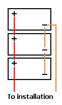
then for 4 or more I'll be doing terminal blocks like Carbioocoot is showing.. -
Re: HELP needed; Wire sze for minimum voltage drop, etc.; full house 12v lighting off-grYo ouighta bee ashmed!
 Is this better?
Semantics, yes..., I think we all understand I wanted to minimise voltage drop (as per title) to an acceptable level and the advice sought was indeed in regards to wire size, connectors & connections/wiring, switches, etc. and the bottom line was what you've outlined in one sentence; the integrity of the system and for that matter how much voltage drop I will allow will depend on the cost of components. I wasn't trying to achieve the absolute minimum but wanted advice on how to reduce voltage drop. Perhaps I should have used 'wire size to REDUCE voltage drop' to please semantic purists?
Most forums will contain a large amount of grammatical errors, mainly due to participants abbreviating to keep posts short & sweet but also due to the new gen of SMS lingo.
I'm 'old school' in regards to that however, my language skills are limited since english is my fourth language.
'Jack of all trades, master of none' comes to mind...
It seems a shame to waste a whole page on rectifying semantics when the question is pretty clear to most participants!Cariboocoot wrote: »Okay I fixed the typo in the thread title. It only goes to show we read what we think is there and not what really is.
It will also confuse anyone reading this thread now as to what the hoopla was about.
Ordinarily we only do that sort of thing if it would affect a search (misspelling of key words). Otherwise correcting typos would be a full-time job. :roll:
Thanks for fixing the typo, it bothered me every time I logged on.Cariboocoot wrote: »Something like this example (includes individual battery string fuses and inverter fuse).
Thanks Marc,
You've nailed it, confirmed my understanding of Niel's explanation.i'm not sure if you are following me on this or not.
in the 3rd drawing we will first look only at the left side where the + is concerned. the red wire to the far left is the combined output of all of the + strings. you should note now that the drawing shows individual batteries being paralleled, but this is just as easily a series string of batteries being paralleled. anyway, the main + lead is tied with the other + leads that are going to the main + post of each string in equal lengths of wire to keep the resistance identical between strings. now each of those + leads to the individual battery strings will have a fuse or breaker inserted of a value that is what the main + wire would've had divided by the number of strings for individual fuse values. (i covered this previously)
the - main wire goes to the bus and is also divided up by wires of equal length going to each of the string's battery - points.
this can lose something in translation and is hard to describe at times, but it is really simple.
Thanks Niel,
So are you suggesting the 3rd drawing should have 5 fuses; one from each batteries' + and then one after the bus?
In my case (8 x 6v/220Ah batteries to output 24v/440Ah), if I wire 4 x 6v in series (+ to - from battery to battery) to give me 2 x strings do I then parallel connect the + from the first battery of string 1 to the + of the first battery of string 2 in a bus and connect the - from the last battery of string 1 to the - of the last battery of string 2 in a bus, insert fuses on both strings' + before the bus and a breaker/switch after the + bus? Would this keep the two strings and all batteries in balance?
It's funny how most simple things are hard to explain! -
Re: HELP needed; Wire sze for minimum voltage drop, etc.; full house 12v lighting off-gr
Okay, with two strings there's two ways of doing it: one with battery fuses and bus bars (or common points), the other without the individual fuses (they are not essential; just extra insurance against things going "poof!").
With either, you first wire your four 6 Volt batteries in series to create 24 Volt strings.
The simple method is then to parallel the (-) and (+) of the two strings. You then connect your inverter lines (with fuse/breaker) and charge controller lines (with fuse/breaker) so that the negatives connect to the negative of one battery string while the positives connect to the positive of the other battery string. This is called "diagonal wiring".
The more complex method which works with two or more parallel strings involves using equal length wires (all negatives the same, all positives the same) from each battery string to the positive and negative bus bars/common points. This is the design where you would put individual fuses on the positive side of each battery string. The bus bars are then the connecting point for the inverter and charge controller wiring (each with its own circuit protection).
It's perfectly simple, aside from being somewhat complex. -
Re: HELP needed; Wire sze for minimum voltage drop, etc.; full house 12v lighting off-grCariboocoot wrote: »Okay, with two strings there's two ways of doing it: one with battery fuses and bus bars (or common points), the other without the individual fuses (they are not essential; just extra insurance against things going "poof!").
With either, you first wire your four 6 Volt batteries in series to create 24 Volt strings.
The simple method is then to parallel the (-) and (+) of the two strings. You then connect your inverter lines (with fuse/breaker) and charge controller lines (with fuse/breaker) so that the negatives connect to the negative of one battery string while the positives connect to the positive of the other battery string. This is called "diagonal wiring".
The more complex method which works with two or more parallel strings involves using equal length wires (all negatives the same, all positives the same) from each battery string to the positive and negative bus bars/common points. This is the design where you would put individual fuses on the positive side of each battery string. The bus bars are then the connecting point for the inverter and charge controller wiring (each with its own circuit protection).
It's perfectly simple, aside from being somewhat complex.
Perfectly simple in your world is complex in my world!:D
I'm glad we finally came to a conclusion and I will use the complex method. I was going around in circles trying to incoprporate method 4 of http://www.smartgauge.co.uk/batt_con.html to balance the batteries. I now know I don't need to do this due to your advice of wiring in series first which only leaves me with two 24v strings to parallel connect. So will the 4 batteries in each string be balanced? My guess is they will in the same way a pocket torch with multiple batteries is balanced having the batteries in series + to - from battery to battery. :cool: I think this is an easy way to explain a series connection as the mind seems to struggle grasping the physics of a square battery where connections are made kind of diagonal due to the position of the + & - terminals. there is a simplified drawing here; http://www.zbattery.com/Connecting-Batteries-in-Series-or-Parallel.
Out of curiousity; I'd like to put the inverter/charge controller on the back wall (facing the door for ease of access and visual checks) above the battery bank vented box but due to the size limitations of my 'power room' one pole from the battery bank would be at the back wall (immediately below the inverter/charge controller and the other pole at the door, about 3ft away from the inverter/charge controller. Would a longer - wire compared to the + wire from the battery bank affect the balance? I can place the inverter/charge controller on the side wall to equalise the length of + & - wires or alternatively keep the wire nearest to the inverter/charge controller the same length as the opposite pole. -
Re: HELP needed; Wire sze for minimum voltage drop, etc.; full house 12v lighting off-gr
Batteries in series always have the same current flowing through them (even though their reaction to that current may vary) because current through a "simple" circuit is the same at all points.
The trouble starts when you add a parallel path at some point in the "simple" circuit. In this case it's the second battery string. If the resistance of the two parallel paths is not the same, the current flow will be uneven. That resistance changes with the length (or size) of the wires connecting the individual batteries in the strings and the strings to the common points in the circuit. Whereas the batteries themselves will have slightly differing resistance, the idea is to reduce any additional variation between the strings by making sure wires are of equal size and length. The diagonal wiring method does this by offsetting the current flow through the negative and positive parallel connectors: the resistance of the negative connector is added to one bank and the corresponding resistance of the positive connector is added to the other.
Got a headache yet?
As for the other question, it does not matter if the positive and negative wires from the common points to the load or charge source are of equal length, as each figures as one resistance segment of the same circuit. The only time different wire lengths will upset the balance is if they are in the parallel section of the wiring. You can in fact have 3' negative wire on one string with a 1' positive wire, and have the other string with a 1' negative wire and a 3' positive wire: the wire lengths in both strings add up to the same total resistance.
Pass the aspirin, will you? -
Re: HELP needed; Wire sze for minimum voltage drop, etc.; full house 12v lighting off-grCariboocoot wrote: »Batteries in series always have the same current flowing through them (even though their reaction to that current may vary) because current through a "simple" circuit is the same at all points.
The trouble starts when you add a parallel path at some point in the "simple" circuit. In this case it's the second battery string. If the resistance of the two parallel paths is not the same, the current flow will be uneven. That resistance changes with the length (or size) of the wires connecting the individual batteries in the strings and the strings to the common points in the circuit. Whereas the batteries themselves will have slightly differing resistance, the idea is to reduce any additional variation between the strings by making sure wires are of equal size and length. The diagonal wiring method does this by offsetting the current flow through the negative and positive parallel connectors: the resistance of the negative connector is added to one bank and the corresponding resistance of the positive connector is added to the other.
Got a headache yet?
As for the other question, it does not matter if the positive and negative wires from the common points to the load or charge source are of equal length, as each figures as one resistance segment of the same circuit. The only time different wire lengths will upset the balance is if they are in the parallel section of the wiring. You can in fact have 3' negative wire on one string with a 1' positive wire, and have the other string with a 1' negative wire and a 3' positive wire: the wire lengths in both strings add up to the same total resistance.
Pass the aspirin, will you?
Headache? Yeah, I must be mildly masochistic, asking for more...:roll:
All wires will be of equal length in my setup, ie between batteries and then between strings. Thanks for confirming I can have a longer negative from the bus of the battery bank to the UPS, it will look better on the back wall and be accessible rather than twisting sideways to get to it if it were on the side wall.
That's it for now..., you've been of great assistance Marc.
Once I have the B bank wired I'll most definitely be back for more headaches! Mmmm...., headaches!;)
Just a couple more things; would you install the battery monitor inside the 'power room' or outside so it can be monitored in passing (games room wall adjacent to 'power room'?
When finally having wired all batteries in series to end up with two strings, which parallel connection is safer to do first; positive or negative? -
Re: HELP needed; Wire sze for minimum voltage drop, etc.; full house 12v lighting off-gr
Put the monitor where you want. There's a limit to how far from the shunt it can be, but otherwise whatever is convenient to you. -
Re: HELP needed; Wire sze for minimum voltage drop, etc.; full house 12v lighting off-grCariboocoot wrote: »Put the monitor where you want. There's a limit to how far from the shunt it can be, but otherwise whatever is convenient to you.
Thanks, I was asking for your personal opinion based on experience.
There was another question I've just added to my previous post (you may have missed it): When finally having wired all batteries in series to end up with two strings, which parallel connection is safer to do first; positive or negative? -
Re: HELP needed; Wire sze for minimum voltage drop, etc.; full house 12v lighting off-gr
It doesn't matter: no current can flow until both connections are made and the circuit is completed. Between the two battery strings there should be almost no current flow; any spark will be a small one.
The same is not true of hooking up the inverter, which is why a proper disconnect is recommended. You want the connection made instantly. -
Re: HELP needed; Wire sze for minimum voltage drop, etc.; full house 12v lighting off-gr
All true, and the reason cable length makes a difference is that the internal resistance of a lead acid cell is extremely low, so low that the resistance differential between different lengths of even very large diameter copper wires in a parallel circuit of lead acid cells can be enough to make a significant difference in the current in charge/discharge cycles between the branches of the circuit. It's also why it's a very bad idea to mix battery types/capacities/ages because those factors make differences between the cell resistances in the batteries, which has the same effect.Cariboocoot wrote: »Batteries in series always have the same current flowing through them (even though their reaction to that current may vary) because current through a "simple" circuit is the same at all points.
The trouble starts when you add a parallel path at some point in the "simple" circuit. In this case it's the second battery string. If the resistance of the two parallel paths is not the same, the current flow will be uneven. That resistance changes with the length (or size) of the wires connecting the individual batteries in the strings and the strings to the common points in the circuit. Whereas the batteries themselves will have slightly differing resistance, the idea is to reduce any additional variation between the strings by making sure wires are of equal size and length. The diagonal wiring method does this by offsetting the current flow through the negative and positive parallel connectors: the resistance of the negative connector is added to one bank and the corresponding resistance of the positive connector is added to the other.
Got a headache yet?
As for the other question, it does not matter if the positive and negative wires from the common points to the load or charge source are of equal length, as each figures as one resistance segment of the same circuit. The only time different wire lengths will upset the balance is if they are in the parallel section of the wiring. You can in fact have 3' negative wire on one string with a 1' positive wire, and have the other string with a 1' negative wire and a 3' positive wire: the wire lengths in both strings add up to the same total resistance.
Pass the aspirin, will you?
If a branch of a parallel battery circuit is being charged and discharged at a lower rate than another branch, that will eventually cause the cell resistance of the batteries in that branch to rise above the resistance in the other branch, which starts a feedback cycle. Higher resistance means less current, less current causes higher resistance. It's a delicate balancing act to prevent that from happening and it's why a few big batteries in series is much better than a bunch of little batteries in parallel.
That's the way I understand it, anyway, and if I am mistaken, I am sure that someone in here will set me straight. -
Re: HELP needed; Wire sze for minimum voltage drop, etc.; full house 12v lighting off-gr
That's right. That's the whole imbalance problem in a nutshell. The longer it goes on, the worse it gets as the lower-charged batteries sulphate more raising their internal resistance further. Eventually their capacity lowers to the point where they're just a parasitic pathway around the batteries doing the work; a small current leak that provides no power. -
Re: HELP needed; Wire sze for minimum voltage drop, etc.; full house 12v lighting off-grCariboocoot wrote: »Wire the batteries in series first, to create the strings of the proper Voltage. Each one of these strings would have its own fuse according to the expected current draw. In theory this value would be the total expected current divided by the number of strings, but in practice you can go higher all the way up to the maximum value for the wire.
Then make the parallel connections for (+) and (-) at each end.
Hi Marc,
Could you please advise the fuse/breaker sizes for my setup?
2 x 24v/220Ah strings; fuse rating for each string=
1 x 240v/440Ah battery bank; from bus (after parallel connection of both strings) to charge controller, DC breaker/switch rating=
Can the battery IN to the inverter be connected to the battery OUT from the charge controller via the same bus?
If not; 1 x 240v/440Ah battery bank; from bus (after parallel connection of both strings) to inverter, DC breaker/switch rating=
Inverter 3000w/6000w to load 240v AC OUT, breaker/switch rating=
AC IN 240v to Victron MultiPlus 3000/70/16, breaker/switch rating=
This unit doesn't have a second AC output (inverter bypass), only the new models now have it. What do I need to loop the 240v AC to bypass the unit; before the 240v IN to after the 240V inverter OUT?
Am I being lazy asking you to work this out for me? Can't get my head around all the ratings & current draw...,
sorry. -
Re: HELP needed; Wire sze for minimum voltage drop, etc.; full house 12v lighting off-gr
Okay, battery fuse ratings: how much does the inverter require in fuse capacity? The individual battery fuses must be at least 1/2 that and up to the full capacity.
The charge controller breaker/fuse needs to be rated for its output. A 60 Amp controller would have an 80 Amp circuit protector (if there isn't a specific manufacturer's recommendation).
When you have batteries connected to a bus bar or common point, that is where the inverter and charge controller connect as well (hence the term common point).
If you need to "wire around" the inverter completely (bypass) you need a transfer switch to change the load circuits from the inverter output to the utility power (protected by breaker) and a method of shutting off the AC IN to the inverter (such as turning off its breaker). You can use the same AC feed & breaker, but then you need two transfer switches: one to take the AC off the inverter and connect it to the "Load feed", the other to take the Load off the inverter and connect it to the "Load feed".
You know I charge $110 per hour, right? And I don't take kangaroos in payment! :P -
Re: HELP needed; Wire sze for minimum voltage drop, etc.; full house 12v lighting off-grCariboocoot wrote: »You know I charge $110 per hour, right? And I don't take kangaroos in payment! :P
Hey Marc,
You're worth every cent and I probably owe you a few thousand $ by now!
Kangarros have now been superseeded by Euro's..., not the crappy european currency though, these are proper, Australian Euro's! http://ezinearticles.com/?The-Euro-is-a-Small-Kangaroo&id=3840768
How many do I owe you?


Categories
- All Categories
- 233 Forum & Website
- 140 Solar Forum News and Announcements
- 1.3K Solar News, Reviews, & Product Announcements
- 181 Solar Information links & sources, event announcements
- 894 Solar Product Reviews & Opinions
- 252 Solar Skeptics, Hype, & Scams Corner
- 22.5K Solar Electric Power, Wind Power & Balance of System
- 3.5K General Solar Power Topics
- 6.7K Solar Beginners Corner
- 1K PV Installers Forum - NEC, Wiring, Installation
- 2.1K Advanced Solar Electric Technical Forum
- 5.6K Off Grid Solar & Battery Systems
- 428 Caravan, Recreational Vehicle, and Marine Power Systems
- 1.1K Grid Tie and Grid Interactive Systems
- 656 Solar Water Pumping
- 816 Wind Power Generation
- 621 Energy Use & Conservation
- 623 Discussion Forums/Café
- 316 In the Weeds--Member's Choice
- 74 Construction
- 125 New Battery Technologies
- 108 Old Battery Tech Discussions
- 3.8K Solar News - Automatic Feed
- 3.8K Solar Energy News RSS Feed