Internal wiring of a panel
Comments
-
Re: Internal wiring of a panel
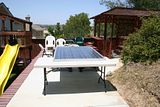
Here are a couple more photos of the panel and surrounding area.
Joe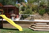
-
Re: Internal wiring of a panel
Just wanted to know if anyone is having continuing problems seeing the photos I have been posting. They are all done exactly the same each time, so if you can see any, you should be able to see all. But, if people are having problems, I will try another method or two to see if I can fix any problems. Please let me know one way or another if you would. Thanks....
Joe -
Re: Internal wiring of a panel
Photos are looking A-OK for me.
-BillNear San Francisco California: 3.5kWatt Grid Tied Solar power system+small backup genset -
Re: Internal wiring of a panel
:? Photos? What Photos?
Just kidding, they come through just fine.
Wayne -
Re: Internal wiring of a panel
Photos look great.
I didn't grasp intuitively how large your panel was, but now I do. It's big enough to play ping-pong on! -
Re: Internal wiring of a panel
Hey, that's a thought. Set up some lights around it, a net, and play night ping pong. Just wish it was not so heavy to move around, 107 lbs and awkward as all git out. Glad most people seem to be able to see the photos too. Thanks of the come backs....
Joe -
Re: Internal wiring of a panel
Joe,
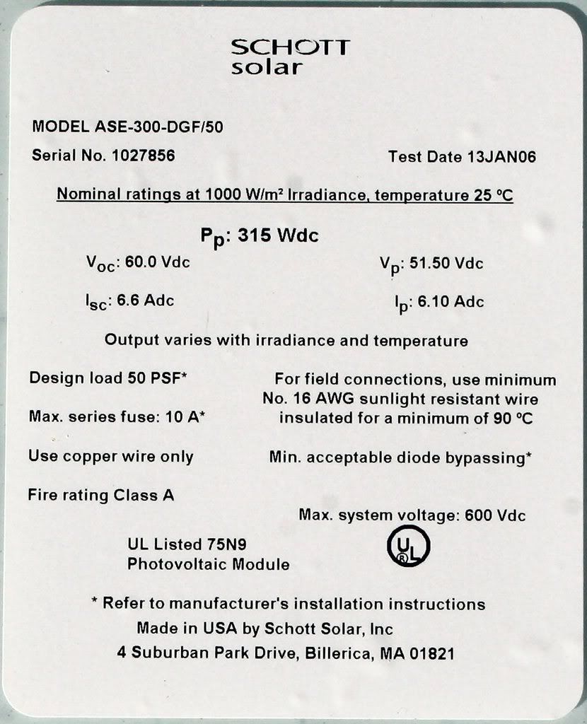
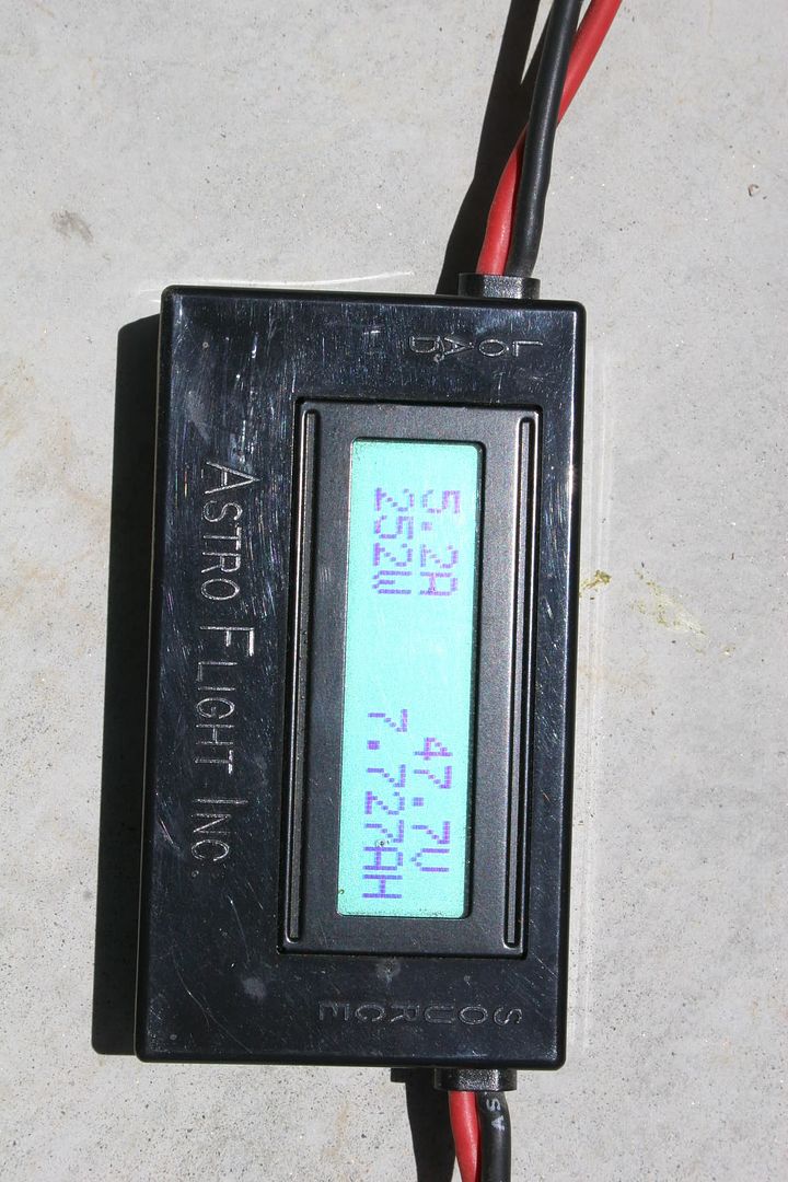
I suspect you're seeing pretty realistic performance out of your module. Specifically, using PTC specs, which includes 68 F / 20 C ambient temperature, the [url=http://]California Energy Commission[/url] rating for your module is 269.3 W. Factoring in likely higher ambient temperature, which reduces Vmp, some diffusion from the damaged glass, and a less than optimal load, and your numbers appear to be in the right ball park.
HTH,
Jim / crewzer -
Re: Internal wiring of a panel
I think your information and evaluation is most likely right on line. I thank you for it as it gives me more insight into just what I have onhand as far as the panel is concerned. The real world performance seems to indicate that the panel would be a useful addition to the project I want to power. Just need to come up with that MX60 I guess. Any thoughts or suggestions on that subject would be appreciated too. I am totally open to offers if anyone has a trade in mind....
Joe -
Re: Internal wiring of a panel
Solor cell (assuming silicon) looks like simply a forward biased diode. The sun energy creates a current source that, if not loaded will result in all the current going down the forward biased diode inherent to the cell. This creates an open circuit voltage at the voltage of forward biased diode of between 0.55 and 0.65 vdc. The amount the sun intensity, the greater the current and higher the diode voltage drop.
The trick is to load the diode to a point slightly below the voltage of the inherent diode conduction of the solar cell. These means the maximum yield will occur at about 0.4 to 0.5 vdc.
All this depends on temperature where the silicon diode has a -2.5 mV per degree C coefficient. The hotter the panel the lower Vt of the diode so the lower the maximum loaded voltage can be before the inherent diode of cell bleeds significant current. If you do not load the cell, all this energy goes into heating the solar cell. Since the cell is only about 18% efficient to start with, the cell won't get that much hotter then is does loaded. Think of it like the hood temp of a dark colored car in the sun.
Cool the cell and the loaded voltage can be raised to 0.7 v, yielding more power from the cell (with sun light)
Finally, put 72, or so of these in series and you have a 36 vdc solar panel.
Regards,
RC -
Re: Internal wiring of a panel
Not sure what this has to do with the subject, but thanks for the information....
Joe -
Re: Internal wiring of a panel
The panel shown throughout this thread is available HERE if anyone is interested.
Joe


Categories
- All Categories
- 231 Forum & Website
- 138 Solar Forum News and Announcements
- 1.3K Solar News, Reviews, & Product Announcements
- 181 Solar Information links & sources, event announcements
- 893 Solar Product Reviews & Opinions
- 252 Solar Skeptics, Hype, & Scams Corner
- 22.5K Solar Electric Power, Wind Power & Balance of System
- 3.5K General Solar Power Topics
- 6.7K Solar Beginners Corner
- 1K PV Installers Forum - NEC, Wiring, Installation
- 2.1K Advanced Solar Electric Technical Forum
- 5.6K Off Grid Solar & Battery Systems
- 428 Caravan, Recreational Vehicle, and Marine Power Systems
- 1.1K Grid Tie and Grid Interactive Systems
- 656 Solar Water Pumping
- 816 Wind Power Generation
- 620 Energy Use & Conservation
- 623 Discussion Forums/Café
- 316 In the Weeds--Member's Choice
- 74 Construction
- 125 New Battery Technologies
- 108 Old Battery Tech Discussions
- 3.8K Solar News - Automatic Feed
- 3.8K Solar Energy News RSS Feed