solar diagram
Options

Ringo
Registered Users Posts: 6 ✭
This is a rough diagram of what I am going to be installing on my rv.
Can you tell me what I am missing or if you see anything wrong?
-From the panels to the combiner is 4.5ft of 10 gauge.
-From the combiner to the 30 amp breaker is 2 ft of 8 gauge.
-From the breaker to the Charge controller is 14 ft of 8 gauge.
-From the controller to the other 30 amp breaker is 3 ft of 8 gauge.
-From the 30 amp breaker to the t-145 batteries is 10 inches of 8 gauge.
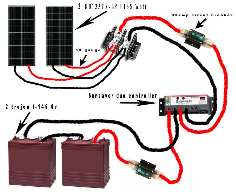
The reason I am going with the duo is I am going to charge my 12v trolling motor battery and it is also my back up battery in the case one of my 6v goes. I,ll pull the six volts and put in one 12 v.
from the Batteries (soon to come) will be an 1750watt inverter
Thanks for any input.
Ringo
Can you tell me what I am missing or if you see anything wrong?
-From the panels to the combiner is 4.5ft of 10 gauge.
-From the combiner to the 30 amp breaker is 2 ft of 8 gauge.
-From the breaker to the Charge controller is 14 ft of 8 gauge.
-From the controller to the other 30 amp breaker is 3 ft of 8 gauge.
-From the 30 amp breaker to the t-145 batteries is 10 inches of 8 gauge.
The reason I am going with the duo is I am going to charge my 12v trolling motor battery and it is also my back up battery in the case one of my 6v goes. I,ll pull the six volts and put in one 12 v.
from the Batteries (soon to come) will be an 1750watt inverter
Thanks for any input.
Ringo
Comments
-
Re: solar diagram
You really don't need the 30 Amp circuit breaker between the solar panels and the charge controller. The two solar panels can never generate enough current to ever pop the breaker.
I would highly suggest a Remote Battery Temperature Sensor for faster and more accurate battery charging.
-BillNear San Francisco California: 3.5kWatt Grid Tied Solar power system+small backup genset -
Re: solar diagram
Thanks
Bill
The only reason for the 30 amp circut breaker between the panels and the controller is as a shut off.
If I ever need to work on the controller or anything else I don't have to climb on the roof and try to block my panels with something.
As for the temp sensor , yes I am going to have one and the remote meter in the camper as well.
Other than that everything looks ok?
Thanks again
Ringo -
Re: solar diagram
The "normal stuff"
The frame of the solar panels should be grounded to your RV chassis (to prevent shock).
Normally, there would be a heavy gauge wire from the battery negative terminal to the chassis ground.
Place all fuses/circuit breakers close to the source of power (battery bank). Each breaker/fuse should be rated for the wire capacity that leaves the breaker (i.e., a 14 gauge wire should have a 15-20 amp fuse/breaker). Always plan on the fuse+wire to be, at least, 1.25x larger than the maximum continuous planned load current.
My personal suggestion, I really like battery monitors. Granted they are not perfect but they do a good job of letting people see how well the battery is being recharged after use. Probably the number 1 killer of batteries is simply to much discharging and too little recharging (also known as "deficit charging"). In any case, you should also have a good quality hydrometer to check the battery cells occasionally for proper charge levels.
You don't show an AC Battery charger (shore power / generator). Most people cannot put enough solar panels on an RV to generate 100% of their needed power. Adding a heavy load, such as recharging a trolling motor pack, is probably going to make the deficit worse.
Just to give you an idea... Assuming you are in very nice weather, you tilt the panels towards the noon day sun, and you have a good 5 hours of noon time sun per day (summer months)--realistically (assuming a 0.52 derating factor for system)--the amount of daily useful solar charge you can use from your AC inverter would be:- 2x 135 Watts * 5 hours of full sun * 0.52 system efficiency = 702 Watt*Hours per day
So--that gets back to our classic song here--- Conservation, conservation, conservation... Convert lighting to LED/Florescent, avoid phantom loads (unplug cell phone chargers, radio, tv, etc. when not in use), turn off inverter when not in use, etc...
If you want 120 VAC power much of the time (say at night to turn on a light/appliance without flipping the DC breaker)--take a look at a Morning Star 300 watt 12 volts Pure Sine Wave inverter (around $260)... It is very efficient, clean power, and has a "standby mode" that does not draw much power when there are no AC loads (requires around 8 watts of AC load to "turn on"). It also has a remote power off line that may be handy for you too.
An AC inverter will pull around 8 watts of load with no external power--leave it on 24 hours per day:- 8 watts * 24 hours = 192 Watt*Hours per day
Do you have your backup power source and charger picked out / operational yet?
-BillNear San Francisco California: 3.5kWatt Grid Tied Solar power system+small backup genset -
Re: solar diagram
our camper has an onan 2500 gen built in. We have had the camper since fall of 07 and have use the gen, maybe a total of 15 hours.
When we go off the grid camping we can go for 4 days before I worry about the batteries We use barley any power, The solar is to keep them topped up and healthy. The inverter is still a maybe , I'll see if we need it after a few trips into the bush.
95% of our appliances are 12v DC.
Tv,dvd,radio,lights and heater. I have installed LED's into all our main light fixtures
And the sun saver duo charge controller will do 90% to the house battery bank and 10% to the other bank. I can set it to 50/50 if i wanted. The charge controller will automaticlly switch to %100 chargeing to the uncharged battery bank when the other battery bank is full.
As for grounding there is a grounding lug on the roof that was preinstalled for the factory solar. I will be grounding the panels to that.
Thanks for the tips
With those two batteries (T-145's) what could I run with an 1750 inverter and how long would it last?
What I think we would use it for would be coffeeMaker and Maybe the microwave for a few minutes.
Thanks
Dave -
Re: solar diagram...
With those two batteries (T-145's) what could I run with an 1750 inverter and how long would it last?
What I think we would use it for would be coffeeMaker and Maybe the microwave for a few minutes.
Coffee maker puts all power into the water and vessel.
Microwave wastes about 50% of the power as heat in the magnatron tube (that's it's cooling fan you hear when turned on)Powerfab top of pole PV mount | Listeroid 6/1 w/st5 gen head | XW6048 inverter/chgr | Iota 48V/15A charger | Morningstar 60A MPPT | 48V, 800A NiFe Battery (in series)| 15, Evergreen 205w "12V" PV array on pole | Midnight ePanel | Grundfos 10 SO5-9 with 3 wire Franklin Electric motor (1/2hp 240V 1ph ) on a timer for 3 hr noontime run - Runs off PV ||
|| Midnight Classic 200 | 10, Evergreen 200w in a 160VOC array ||
|| VEC1093 12V Charger | Maha C401 aa/aaa Charger | SureSine | Sunsaver MPPT 15A
solar: http://tinyurl.com/LMR-Solar
gen: http://tinyurl.com/LMR-Lister , -
Re: solar diagram
Assuming those are Trojan T-145 batteries...
Batteries have "different capacity" based on how fast you are drawing them down... (2x 6 volt batteries in series--voltage doubles, Amp*Hour capacity remains the same).
For Solar RE--we generally start with a C/20 or 20 Hour Rate... They are rated at 260 Amp*Hour:- 260 AH/20 hours = 13 amp rate
- 13 amps * 12 volts = 156 watts DC
- 156 Watts DC * 0.85 inverter eff = 133 watts at the AC plug
So, at the 20 Hour rate, 133 watts from the inverter, you would get:- 20 Hours * 50% usage = 10 hours
- 20 hours * 80% usage = 16 hours
- 25 amps * 530 minutes * 1/60 min per hour = 221 AH
- 75 amps * 145 minutes * 1/60 min per hour = 181 AH
- 75 amps * 12 volts * 0.85 inverter eff = 765 watts
- 181 AH * 1/75 amps * 0.50 battery discharge = 1.2 hours
- 181 AH * 1/75 amps * 0.80 battery discharge =1.9 hours
- 181 AH / 75 amps = 2.4 = C/2.4 discharge rate--about the maximum continuous you would want from this size bank
-BillNear San Francisco California: 3.5kWatt Grid Tied Solar power system+small backup genset -
Re: solar diagram
The only thing I would want different would be MPPT Charge Controllers but your talking more cash for one of those.
I know BlueSky has some Charge Controllers that will dump the extra current after the main battery bank is charged into an auxiliary load or a Extra Battery you want to keep charged.
I know the MPPT just about Always puts more current into my batteries vs not using MPPT. Just depends on how much you need those extra Amp Hours Every day. -
Re: solar diagramAssuming those are Trojan T-145 batteries...
Batteries have "different capacity" based on how fast you are drawing them down... (2x 6 volt batteries in series--voltage doubles, Amp*Hour capacity remains the same).
For Solar RE--we generally start with a C/20 or 20 Hour Rate... They are rated at 260 Amp*Hour:- 260 AH/20 hours = 13 amp rate
- 13 amps * 12 volts = 156 watts DC
- 156 Watts DC * 0.85 inverter eff = 133 watts at the AC plug
So, at the 20 Hour rate, 133 watts from the inverter, you would get:- 20 Hours * 50% usage = 10 hours
- 20 hours * 80% usage = 16 hours
- 25 amps * 530 minutes * 1/60 min per hour = 221 AH
- 75 amps * 145 minutes * 1/60 min per hour = 181 AH
- 75 amps * 12 volts * 0.85 inverter eff = 765 watts
- 181 AH * 1/75 amps * 0.50 battery discharge = 1.2 hours
- 181 AH * 1/75 amps * 0.80 battery discharge =1.9 hours
- 181 AH / 75 amps = 2.4 = C/2.4 discharge rate--about the maximum continuous you would want from this size bank
-Bill
Once i got my head wrapped around the math, Yes!
Thanks for all the input -
Re: solar diagramAssuming those are Trojan T-145 batteries...
Batteries have "different capacity" based on how fast you are drawing them down... (2x 6 volt batteries in series--voltage doubles, Amp*Hour capacity remains the same).
For Solar RE--we generally start with a C/20 or 20 Hour Rate... They are rated at 260 Amp*Hour:- 260 AH/20 hours = 13 amp rate
- 13 amps * 12 volts = 156 watts DC
- 156 Watts DC * 0.85 inverter eff = 133 watts at the AC plug
So, at the 20 Hour rate, 133 watts from the inverter, you would get:- 20 Hours * 50% usage = 10 hours
- 20 hours * 80% usage = 16 hours
- 25 amps * 530 minutes * 1/60 min per hour = 221 AH
- 75 amps * 145 minutes * 1/60 min per hour = 181 AH
- 75 amps * 12 volts * 0.85 inverter eff = 765 watts
- 181 AH * 1/75 amps * 0.50 battery discharge = 1.2 hours
- 181 AH * 1/75 amps * 0.80 battery discharge =1.9 hours
- 181 AH / 75 amps = 2.4 = C/2.4 discharge rate--about the maximum continuous you would want from this size bank
Did I answer your questions?
-Bill
Bill, you had me until the bold part. What is that, and how did you get the numbers? I haven't seen those figures before. My apologies for my ignorance....
-
Re: solar diagram
Bob,
Bottom left of this page: Trojan T-145 batteries
Not one of the more standard method to measure battery energy (C/8, C/20, C/100).... But it does give us some more information (in this case, 75 amp continuous discharge is probably the maximum recommended (high continuous discharge may shorten battery life/cause over heating).
Note that my "computations" are for 12 volts--that is assuming 2x of these 6 volt batteries in series.
The actual "power" (AH*V = Watt*Hours) per battery is 1/2 (6 volt for one battery vs 12 volts for two batteries in series).
Picking 75 amps was just because I was was trying to show the difference in battery "Capacity" between low current (13 amps) and heavy current (75 amps)... No other reason that I did not pick one of the other current values other than just to keep things simple by working with just 13 and 75 amps to show the spread.
The person who discovered the relationship between discharge rate and AH capacity got to name it Peukert's law (Summary). Note that different battery designs will have different Peukert factors. And as a battery ages, the Peukert factor drifts (batteries are less able to deliver energy as they age).
In your case--the two values I used sort of bracket the min/maximum use of your 1,750 Watt Inverter (since you did not give us a specific wattage/current level).
-BillNear San Francisco California: 3.5kWatt Grid Tied Solar power system+small backup genset -
Re: solar diagram
I have been looking for inline DC breakers like the one's pictured at the beginning of this post.
Can anyone tell me where to find them?
Thank You! -
Re: solar diagram
looks like one I got off Ebay.
there are US based suppliers.
EJ
KID #51B 4s 140W to 24V 900Ah C&D AGM
CL#29032 FW 2126/ 2073/ 2133 175A E-Panel WBjr, 3 x 4s 140W to 24V 900Ah C&D AGM
Cotek ST1500W 24V Inverter,OmniCharge 3024,
2 x Cisco WRT54GL i/c DD-WRT Rtr & Bridge,
Eu3/2/1000i Gens, 1680W & E-Panel/WBjr to come, CL #647 asleep
West Chilcotin, BC, Canada -
Re: solar diagram
would you recommend them? They are DC...right? -
Re: solar diagram
they are for car stereo and rate from ~ 30 A thru 150A or more.
Work fine for a small system and no problem with fuses blowing, ask me why I know... work just like a regular Circuit breaker.
search for 'circuit breaker 12 v'
Eric
KID #51B 4s 140W to 24V 900Ah C&D AGM
CL#29032 FW 2126/ 2073/ 2133 175A E-Panel WBjr, 3 x 4s 140W to 24V 900Ah C&D AGM
Cotek ST1500W 24V Inverter,OmniCharge 3024,
2 x Cisco WRT54GL i/c DD-WRT Rtr & Bridge,
Eu3/2/1000i Gens, 1680W & E-Panel/WBjr to come, CL #647 asleep
West Chilcotin, BC, Canada -
Re: solar diagram
Try a marine supply like http://www.blueheronmarine.com/Blue-Sea-Panel-Mount-Circuit-Breakers-4778 -
Re: solar diagram
Hi,
What kind of breaker do you guys use between the battery bank and the CC?
I'm looking into what is the best option there, since its such a high current that you might at times draw and I have not come across any 12VDC 200 Amp circuit breakers yet?..
Thanks for the help!
G -
Re: solar diagram
Do you mean, between the battery bank and inverter? 200 amps to the charge controller is a bit much!
Large DC breakers can be found here http://store.solar-electric.com/oudcbr.html -
Re: solar diagram
to add to audredger's post it depends on what the cc is to output and other preferences as circuit breakers may be preferred by some. as long as the breaker/fuse is properly rated for the dc voltage and handles the current levels required of it you will be fine. -
Re: solar diagram
Ah ok. I see what you mean.. What I meant was a breaker between battery and CC to protect the CC from a possible surge or short circuit... But I see now I was thinking backwards. The Breaker has to be big enough to carry the current coming from the CC to the battery. Thanks!


Categories
- All Categories
- 243 Forum & Website
- 150 Solar Forum News and Announcements
- 1.4K Solar News, Reviews, & Product Announcements
- 191 Solar Information links & sources, event announcements
- 919 Solar Product Reviews & Opinions
- 256 Solar Skeptics, Hype, & Scams Corner
- 22.5K Solar Electric Power, Wind Power & Balance of System
- 3.5K General Solar Power Topics
- 6.7K Solar Beginners Corner
- 1K PV Installers Forum - NEC, Wiring, Installation
- 2.1K Advanced Solar Electric Technical Forum
- 5.5K Off Grid Solar & Battery Systems
- 438 Caravan, Recreational Vehicle, and Marine Power Systems
- 1.1K Grid Tie and Grid Interactive Systems
- 652 Solar Water Pumping
- 829 Wind Power Generation
- 626 Energy Use & Conservation
- 626 Discussion Forums/Café
- 303 In the Weeds--Member's Choice
- 91 Construction
- 124 New Battery Technologies
- 108 Old Battery Tech Discussions
- 3.8K Solar News - Automatic Feed
- 3.8K Solar Energy News RSS Feed