Information overload-help complete panel system

TXtrucker
Solar Expert Posts: 28 ✭
I have done a lot of reading on the solar panel topic, but I need a little help in completing my system. I will have 6 145 watt 12v panels, 4 6v golf cart batteries, Outback FM60 charge controller, and a 12v 1800 watt Xantrex sine wave inverter. Can someone please start with the panels and explain the best way to connect all the components. I know there may be more than one way to do this, but I am looking for the least complex way. Please include size of wires need and any other components I will need to purchase. I will be happy to answer any questions to help with this problem. Thank you
Comments
-
Re: Information overload-help complete panel system
So, you have a 12 volt battery bank (how many Amp*Hours, type of Battery?).
Your 145 watt "12 volt panels" are really around 17.5 volt Vmp probably (that is a good thing). Basically, as solar PV panels get hot in the sun (and in hot weather), the Vmp voltage falls... You still need Vmp-array-hot>Vbatt-charging+controller voltage drop+wiring voltage drop.
So, still would be a good idea for you to confirm the panel brand/model/Voc/Vmp/Imp/Isc numbers... But assuming Vmp is at least 17.5 volts and Voc is around 22 volts:- The Outback FM family (last I read) is most efficient with Vmp-array ~ 2xVbatt-charging. So that would be two 145 watt panels in series.
- You have the option of running 1/2/3/4 panels in series with your battery/controller configuration (5 panels in series, and during cold/freezing weather, you run the risk of Voc-cold over voltaging your charge controller's 140-150 VDC max input).
- Sending power a fair distance (say over ~10 feet), you will need a lot of expensive copper to run your array with all panels in parallel (plus, you should have 1 fuse/breaker per string when you have 3 or more panel strings in parallel).
- You did not say the distance, but you are looking at 2 panels in series with 3 parallel strings (need fused/breakered combiner box), or you can run 3 panels in series/2 strings in parallel which will allow you to send the power farther on smaller gauge wire.
- So, need to know the distance for the wire run from the array to the battery shed/controller/battery bank.
- With a 12 volt battery bank and a 60 amp charge controller, you can build the array out to ~8 panels "cost effectively" before the FM 60 will start current limiting "a lot" during the middle of the day (note, if you want to add panels, they need to meet some sort of valid series/parallel configuration for your controller).
Your Xantrex 1,800 watt inverter should have information about wiring/fusing... But in general, this is how the math would look without reading the manual:
First, the maximum DC input current for the inverter:- 1,800 watts * 1/10.5 volt batt cutoff * 1/0.85 inverter eff = 202 Amps max continuous
- 1,800 watts * 1/10.5 volt batt cutoff * 1/0.85 inverter eff * 1.25 NEC derating = 252 Amps minimum branch circuit
So, you need to meet two requirements... One is that the wire does not overheat. NEC has a table which is fairly conservative:
Wire Current Ampacities NEC Table 310-16
You can use 4/O cable with the "better" insulation (this table assumes in conduit).
The ABYC (boating) uses this table:
ABYC Wiring Standards
which can allow down to 1/O cable (less than 1/2 the cross sectional area).
The other design factor is voltage drop. What is the maximum power you will draw from the inverter (continuous and peak)... Assuming 1,800 watt continuous and 3,600 peak with 12 volt system (11.5 volt low battery voltage and 10.5 inverter cutoff)--I will suggest 1,800 watts (~202 amps) with a maximum of 0.5 volt drop (allows for surge capacity).
Using a generic voltage drop calculator, 202 amps and 0.5 volt max drop with 1/O and 4/O wiring, the maximum one way distance would be:- 202 amps, 1/O wire -> 10' one way run and ~0.5 volt drop
- 202 amps, 4/O wire -> 20' one way run and ~0.5 volt drop
And you should use ~250 amp fuse/breaker.
Note, lead acid storage batteries have limitations on how much power they can "reliably" deliver... Assuming 4x 6 volt 225 AH golf cart batteries configured as a 12 volt 450 AH battery bank:- 12 volts * 450 AH * 1/8 max continuous load * 0.85 inverter losses = 574 watt max continuous (you can exceed this load, but battery bank will discharge pretty fast and may get warm)
- 12 volts * 450 AH * 1/2.5 max surge load * 0.85 inverter losses = 1,836 watt max surge load (again, recommended for normal operation)
And working backwards from the battery bank size, the recommended amount of solar panel for charging would be (based on 5% to 13% rate of charge):- 450 AH * 14.5 volts charging * 1/0.77 panel+charger derate * 0.05 rate of charge = 424 watt minimum array
- 450 AH * 14.5 volts charging * 1/0.77 panel+charger derate * 0.10 rate of charge = 847 watt "nominal" array
- 450 AH * 14.5 volts charging * 1/0.77 panel+charger derate * 0.13 rate of charge = 1,059 watt "cost effective maximum" array
Again, the above are "conservative" rules of thumb that seem to give a working system for most people. Looking at your system, your inverter is a bit on the "large" size--But everything seems to be sized pretty well otherwise.
So, once we know the distance from the array to the battery/controller location, we can help with the rest of the calcuations.
-BillNear San Francisco California: 3.5kWatt Grid Tied Solar power system+small backup genset -
Re: Information overload-help complete panel system
BB, thanks for the reply. You are correct in the panel voltage. I think the 3 panels in series with 2 strings in parallel will be the way to go. My battery bank will be 4 6v 220ah batteries. 2 wired in series then 2 sets in parallel giving me 440ah at 12v. Distance from panels to combiner box 8 feet, combiner box to charge controller 2 feet, charge controller to batteries 4 feet, and batteries to inverter 2 feet. Will the following wire sizes work? Panels to combiner box #10 awg, combiner box to charge controller #6 awg, charge controller to batteries #2 awg, battery wiring #0/2 awg, and batteries to inverter #0/2 awg.
The wiring from the panels to the combiner box is giving me the most difficulty as there are several ways to do this. I have seen all six panels wired directly to the combiner, 3 panels in series to the combiner, panels in parallel to the combiner, etc. I thing putting 3 panels in series then 2 strings of 3 in parallel to the combiner might be the way to go, but the exact wiring is what is tripping me up.
I hope I provided enough information. Thanks again for your help. -
Re: Information overload-help complete panel system
To series the panels they hook together. for however many your putting in series.. sounds like 3 panels
Then the OPEN lead will go toward the combiner breaker box..
Repeat for 2nd set of 3 panels..
Sounds like you got the same 145 DM Solar panels I have and almost the same setup going.. I too will be in SW Texas hopefully by next summer with the setup..
Heres 2 strings of 3 panels..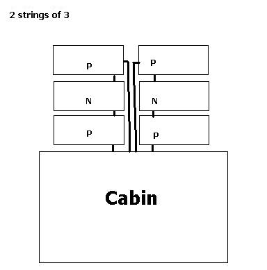
-
Re: Information overload-help complete panel system
Yes, I bought the DM 145w panels. Very good price on Amazon. I am in NE Texas. From your diagram I will take a + and - from each series to the combiner box. Doesn't look too hard. I am still shopping for the combiner box. Going to call the company I bought my charge controller from to get some recommendations. -
Re: Information overload-help complete panel system
It was mentioned not to cut the cable from the panel. I was going to use #10 wire with butt connectors to lengthen the wire to get to the combiner box. Is that not a recommended method? It would be less expensive, but if there is a problem with doing this I will use mc4 connectors. Thanks -
Re: Information overload-help complete panel system
Usually voids the warranty on the panels..
Many places sell 10 AWG MC4 Extension wires.. just buy DOUBLE the length of the run from the combiner box to the closest panel leads..
Upon checking length.. then CUT the wire in half.. you will end up with a + and a - lead to take to the inside of the combiner box that is stripped and a + - connector to hook to the series panels..
Example.. this was a 10 foot MC4 cable.. cut in half.. now its a 5 foot positive and 5 foot negative.
-
Re: Information overload-help complete panel system
Good point on the warranty. Will get the mc4. Thanks -
Re: Information overload-help complete panel systemBB, thanks for the reply. You are correct in the panel voltage. I think the 3 panels in series with 2 strings in parallel will be the way to go. My battery bank will be 4 6v 220ah batteries. 2 wired in series then 2 sets in parallel giving me 440ah at 12v. Distance from panels to combiner box 8 feet,
Normally, we design for 1% to 3% maximum wiring voltage drop. So 2 strings of 3x145 watt panels, assume 17.5 volt Vmp, 8 foot 6 awg run and generic voltage drop calculator:- 145 watt panel / 17.5 Vmp = 8.3 amp Imp
- 8', 6 awg, 8.3 amps -> 0.06 volt drop
- 0.06 volt drop / 3x17.5 Vmp-array = 0.001 drop = 0.1% voltage drop
And 14 awg wire is rated at 15 amps, so you are using much heavier wire, no problem with current.
Your combiner box, if you are not adding more parallel strings, then you do not need it to be fused/breakered. Just use wire nuts or clamping method parallel connect your +/- leads from the array into your single 6 awg string. Make sure you can get to the connections if you ever need to check them (heat/moisture can get into the electrical connection years down the road--Use drip loops to keep water from running into the combiner box/joints).combiner box to charge controller 2 feet, charge controller to batteries 4 feet, and batteries to inverter 2 feet. Will the following wire sizes work? Panels to combiner box #10 awg, combiner box to charge controller #6 awg, charge controller to batteries #2 awg, battery wiring #0/2 awg, and batteries to inverter #0/2 awg.
Every think looks good. Keep +/- wires running together in parallel runs (bundle tie, conduit, etc.). Keeps them from radiating radio interference and/or receiving RF energy from nearby lightning strikes (loops of wire act like better antenna).The wiring from the panels to the combiner box is giving me the most difficulty as there are several ways to do this. I have seen all six panels wired directly to the combiner, 3 panels in series to the combiner, panels in parallel to the combiner, etc. I thing putting 3 panels in series then 2 strings of 3 in parallel to the combiner might be the way to go, but the exact wiring is what is tripping me up.
I hope I provided enough information. Thanks again for your help.
I think "ywhic" has answered the panel wiring question.
If you have lightning in your area, be very careful about grounding. Make sure you run a 6 awg ground wire from the panel/mounting frames to a ground rod at the base of the solar array or to the some ground rod (if close by). Do not run the ground wire down through the middle of your home, run it on the exterior wall directly down to earth/ground rod.
Grounding is a complex issue (grounding of DC battery, AC neutral, etc.)... And it is very possible to do wrong (example of some common mistakes: parallel current paths between AC/DC grounds, grounding the same return wire with two ground rods 10's of feet apart, AC Neutral grounding of a MSW inverter, etc.) can damage equipment or worse.
-BillNear San Francisco California: 3.5kWatt Grid Tied Solar power system+small backup genset -
Re: Information overload-help complete panel system
I was just at my local hardware store and they don't carry 12v dc breakers. Can regular 120v 15 amp breakers be used in a 12v combiner box? -
Re: Information overload-help complete panel system
Never mind my last question. I realize I was wrong on the voltage. I need a 150vdc breaker. Unfortunately my local store does not carry any dc breakers. Will probably order online. -
Re: Information overload-help complete panel system
The only AC breakers that can do DC are Square D QO breakers (or the ones from Midnite Solar which need to be used in there proprietary box..) Square D also make a small 70 Amp $15 load center that uses QO breakers..
The QO breakers are in the isle near the other HOMELITE ones.. they say QO in yellow and blue boxes.. 15 amps breakers are $5.99 each..
Some people use simple ATC AUTO fuses that just go inline with the + wire..
Heres a video.. same idea with fuses .
 https://www.youtube.com/watch?v=zs6WUzP5aAg
Categories
- All Categories
- 243 Forum & Website
- 150 Solar Forum News and Announcements
- 1.4K Solar News, Reviews, & Product Announcements
- 190 Solar Information links & sources, event announcements
- 919 Solar Product Reviews & Opinions
- 256 Solar Skeptics, Hype, & Scams Corner
- 22.5K Solar Electric Power, Wind Power & Balance of System
- 3.5K General Solar Power Topics
- 6.7K Solar Beginners Corner
- 1K PV Installers Forum - NEC, Wiring, Installation
- 2.1K Advanced Solar Electric Technical Forum
- 5.5K Off Grid Solar & Battery Systems
- 438 Caravan, Recreational Vehicle, and Marine Power Systems
- 1.1K Grid Tie and Grid Interactive Systems
- 652 Solar Water Pumping
- 829 Wind Power Generation
- 626 Energy Use & Conservation
- 626 Discussion Forums/Café
- 303 In the Weeds--Member's Choice
- 91 Construction
- 124 New Battery Technologies
- 108 Old Battery Tech Discussions
- 3.8K Solar News - Automatic Feed
- 3.8K Solar Energy News RSS Feed