Power MOSFET question ?
Options
Comments
-
Re: Power MOSFET question ?
You need to make your alum plate as large as possible to mate to the iron below it, use a conductive filler sheet, not heatsink grease. If possible, get the interfaces milled flat, or use some #400 sandpaper to get the iron as flat as possible, no high spots. Check your temps with an IR thermometer, you will be surprised, I'll bet your resistors are way over 212F, closer to 300F. Way beyond what they are rated for.
And move those feed wires to opposite diagonal corners, the end resistor is hogging the load wired as it is currently.Powerfab top of pole PV mount | Listeroid 6/1 w/st5 gen head | XW6048 inverter/chgr | Iota 48V/15A charger | Morningstar 60A MPPT | 48V, 800A NiFe Battery (in series)| 15, Evergreen 205w "12V" PV array on pole | Midnight ePanel | Grundfos 10 SO5-9 with 3 wire Franklin Electric motor (1/2hp 240V 1ph ) on a timer for 3 hr noontime run - Runs off PV ||
|| Midnight Classic 200 | 10, Evergreen 200w in a 160VOC array ||
|| VEC1093 12V Charger | Maha C401 aa/aaa Charger | SureSine | Sunsaver MPPT 15A
solar: http://tinyurl.com/LMR-Solar
gen: http://tinyurl.com/LMR-Lister , -
12V dump load sensor question
While I have the attention of some experts, here's a similar item that I would like to build.
The goal is to monitor a 12V battery and turn on an SSR when the battery
voltage is boosted by the solar charge controller.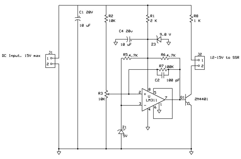
Any hints or suggestions would be appreciated.
Thanks,
Rich -
Re: Power MOSFET question ?
Rich,
Apply my previous comments about the pot having wing resistors and a bypass cap. If you are going to be making these, you should get rid of the zeners and use a 3 terminal voltage regulator. It will save you on some power, be more stable and more reliable. A 78L15 will cost you less than a buck, then you can just replace Z1 with a resistor. Also R1 and Z3 go away.
While I am at it, why not just stick with the FET for the output? Unless you are like me and have a bunch of junque - er, I mean parts lying around.
Joe -
Re: Power MOSFET question ?
Thanks Joe.
I have a bag of those old 2N4401 NPNs. Got 20 for $1 about 30 years ago.
The FETs I've recently acquired, cost more and run bunches of power..
(I just got the new 200V FETs yesterday)!
Pot Wings? I figured that using 10k feed to the 10k pot would give me about 7v in the middle,
so I could use 9V power and keep a safe input range.?.
(I will add a noise cap to the pot sweep arm).
I liked the idea of 9V, since a 12V regulator might be too close to the 12V battery voltage..?.
I do like the LM317 regulators and it would be a snap to set one for 9 or 10V..
But, if I'm doing this reg thing to save a few MA from a 115AH battery..?.
However, if the Ref stability is a lot better, maybe a LM317 would do.?.
What do you think about changing R7 to a pot, to enable hysteresis adjustment? -
Re: Power MOSFET question ?
As far as the regulator goes, yes 9 volts would probably be better for a battery input and wont affect much either. The three terminal reg is just better (IMHO) for this application than a shunt regulator. I view shunt stuff as transient supression or clamping functions. Its just better to use a regulator for reliability, you dont have to waste power to keep it in regulation. In the original design, the HV made it a good choice but in this low voltage design, a linear VR will do a better job.
The pot, Well I like to put wing resistors to limit the range of the pot to the area of operation, it gives you more resolution. So yes, the center of the pow should be at around 5 volts but you will never set the pot to zero volts so why waste the range?
So you would want the bottom of the pot to be at around 4 volts and the top to b e at around 6 volts. This will give you 2 volts over the range of the pot rather than 6 volts.
You can add a hysteresis control mto it but if it is designed for a specific taks, why not just set it for what it needs to be? Be aware that if you mess with the hysteresis, you will also mess with the setpoint, it will become an iterative process to set this up.
Joe -
Re: Power MOSFET question ?
Thanks Joe,
I found a few 7808 regulators this morning, so I used one for the supply.
After I got it working, (using an LED for a load), I found it makes really
good high frequency square-waves as the pot gets around the 5v range.
That would drive my SSR into making AC garbage..
The +8v is clean, so I plugged in a new LM311. No luck.
It's late, so maybe I'll get some troubleshooting time tomorrow night.
Oh-0h.. I just remembered. I didn't put the cap on the wiper arm..
Dang! I wonder if that will help.?. -
Re: Power MOSFET question ?
Assuming no wiring errors, what is going on is telling me you dont have enough hysteresis. Thats what I was saying about the input resistor and the wing resistors. In order to provice Hysteresis, R7 provides positive feedback. Typically there is an input resistor in series with the positive input. Your feedback wiggles the pot around instead of the traditional method. Also, the wing resistors will help this. If you want to make it "right" change R7 to a high value like 1M and then put a 100K in series with the positive input. This will also isolate the hysteresis from the gain and allow you to adjust them independently.
Hope you can visualize what I am saying:D
Joe -
Re: Power MOSFET question ?
Yeah, I can see what you mean. I saw something about the feedback selecting on the web a while back.
Guess I need to pay more attention, to get less T&E..
What I don't want is to have the flip-back occurring at the wrong voltage.
It would be nice to have it turn on at over 13v and turn off around 12.0v.
(My inverter build-in shutdown is 10v).. :grr -
Re: Power MOSFET question ?Yeah, I can see what you mean. I saw something about the feedback selecting on the web a while back.
Guess I need to pay more attention, to get less T&E..
What I don't want is to have the flip-back occurring at the wrong voltage.
It would be nice to have it turn on at over 13v and turn off around 12.0v.
(My inverter build-in shutdown is 10v).. :grr
That should not be a problem, 13 on and 12 off is not an issue, you just have to calculate the divider for the correct trip points. You can calculate the amount of hysteresis by taking the output swing and treating the FB resistor and the input resistor as a divider. For example, if your output is swinging 10 volts and your FB resistor is 10M and the input resistor is 100K you will have 900 mv of hysteresis.
You want the hysteresis network to be a high enough value that it doesn't load the pot wiper.
ETA: One more thing, the Vbe of the transistor will clamp the output swing on the 311. You will need more swing to get the hysteresis to work properly. The easy way is to use a FET but if you keep the BJT then add a base resistor. -
Re: Power MOSFET question ?
Rich, take a look at the TL431 shunt regulator. It has integrated op-amp. reference comparator voltage, 100ma NPN output open-collector pull i.e. most of your circuit components. With an additional transistor inversion to provide positive feed-back for the hysterysis, you are there")
GP -
Re: Power MOSFET question ?
I changed the feed back to 1 megohm, put a 100k on the swing arm of the pot and added a cap to the pot arm as you suggested.
It was acting up when near the setpoint during testing, but I think the chatter
had to do with either the charger pulsing, or the local AM radio station..
It causes RFI in anything that isn't well shielded.
I have it clipped onto the 48v bank (on one 12v battery) now and I'm running
down the SOC to see if I can get it to shut down around 12V..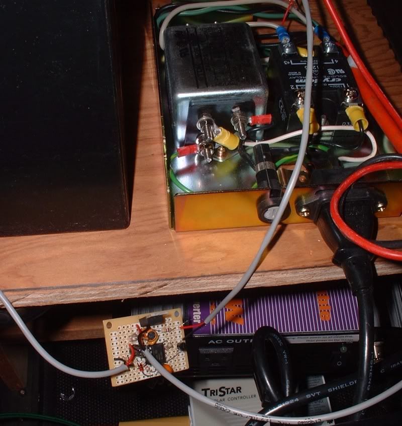
SSR upper right & level detector on lower left.
The back-up unit with the maintenance top-cover off. That's a 10k pot over on the left.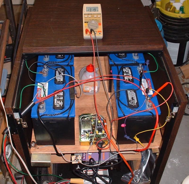
The AC from the SSR feeds some house loads 9(& this PC)via an IOTA switch.
The IOTA box has a 30 second time delay, so maybe chatter won't effect the relay.. -
Re: Power MOSFET question ?
The chattering concerns me, it says you either dont have enough hysteresis or there is noise somewhere. What are you using for an output device? If its still the BJT, you need a base resistor. The base-emitter junction looks like a forward biased diode and will clamp the output swing to .7 volts. If the output is clamped, the positive feedback will not work.
Joe
BTW, where did you get your Crydom SSR? I am looking for a D06D60. -
Re: Power MOSFET question ?The chattering concerns me, it says you either dont have enough hysteresis or there is noise somewhere. What are you using for an output device? If its still the BJT, you need a base resistor. The base-emitter junction looks like a forward biased diode and will clamp the output swing to .7 volts. If the output is clamped, the positive feedback will not work.
Joe
BTW, where did you get your Crydom SSR? I am looking for a D06D60.
I picked some Crydom SSRs years ago when I wanted to use them for controlling
ham radio satellite tracking hardware.
I think the chatter was from the cheapo charger, since I could see it was
changing the battery voltage enough, that it was visible on the VOM display.
Now that I've put connected up the 48v system, the TS-45 isn't
bouncing the voltage much at all.
Plus, the time delay built into the IOTA switch boxes inhibit chatter.
All I hear upstairs is a beep from my grid-fail detector once every 30 seconds.
As the load gets switched back and forth, from grid to back-up.
It's working as is, but It needs a bit more hysteresis..

Categories
- All Categories
- 243 Forum & Website
- 150 Solar Forum News and Announcements
- 1.4K Solar News, Reviews, & Product Announcements
- 191 Solar Information links & sources, event announcements
- 919 Solar Product Reviews & Opinions
- 256 Solar Skeptics, Hype, & Scams Corner
- 22.5K Solar Electric Power, Wind Power & Balance of System
- 3.5K General Solar Power Topics
- 6.7K Solar Beginners Corner
- 1K PV Installers Forum - NEC, Wiring, Installation
- 2.1K Advanced Solar Electric Technical Forum
- 5.5K Off Grid Solar & Battery Systems
- 438 Caravan, Recreational Vehicle, and Marine Power Systems
- 1.1K Grid Tie and Grid Interactive Systems
- 652 Solar Water Pumping
- 829 Wind Power Generation
- 626 Energy Use & Conservation
- 626 Discussion Forums/Café
- 303 In the Weeds--Member's Choice
- 91 Construction
- 124 New Battery Technologies
- 108 Old Battery Tech Discussions
- 3.8K Solar News - Automatic Feed
- 3.8K Solar Energy News RSS Feed