Transfer switch to transfer threephase to single phase, how?
Options

OntheWay
Solar Expert Posts: 36 ✭✭
Hi everybody,
After buying mpp solar brand 3kva inverter, now I am looking on how to integrate it to home breaker box.
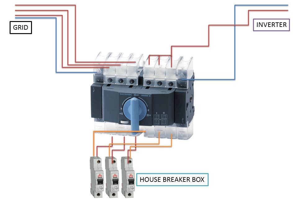
The problem is, the line coming to in-house breaker box is three phase, which is distributed as one line to three breakers, so a total of 9 breakers in the box. On the other hand, inverter is single phase. The lines/routes/outlets (how you name it) I want to energize in the house is, unfortunately are on three different phases. I just cannot find a transfer switch which will allow me to switch from 3phases source to 1phase source. I am living in 220V/50hz region. One solution I am thinking is as the following but not sure whether it works, open for comments:
After buying mpp solar brand 3kva inverter, now I am looking on how to integrate it to home breaker box.
The problem is, the line coming to in-house breaker box is three phase, which is distributed as one line to three breakers, so a total of 9 breakers in the box. On the other hand, inverter is single phase. The lines/routes/outlets (how you name it) I want to energize in the house is, unfortunately are on three different phases. I just cannot find a transfer switch which will allow me to switch from 3phases source to 1phase source. I am living in 220V/50hz region. One solution I am thinking is as the following but not sure whether it works, open for comments:
Comments
-
Note: I did not quite understand the picture in the original post--Not as bad as I thought. But still lots of questions. -Bill
STOP! If I understand your wiring diagram, you will be shorting out your three phase power with a dead short. And you bypassed your circuit breakers.
Three phase power is even more complex and confusing than single phase AC power.
First,, need to understand your three "hot wires" and the Blue wire. There are two types of three phase power. Delta and Wye (or also called "Y" or "Star").
Attachment not found.
Three Phase Wye:
Attachment not found.
The grounded wire that is in the middle of both diagrams is your BLUE wire. Also known as the Neutral in the US.
You can make connections to brown to brown, or blue to brown. And, depending on your type of three phase power, not all blue to brown connections are the same.
To make things more confusing, in the US, both types of three phase power are available (usually commercial buildings) are available (and because of this we have, at least two voltage standards, 240 VAC for 1&3 phase and 208 VAC for 3 phase power).
You need to understand the details of this for your home. How to safely add circuits to your main panel, exactly what line voltage your GT inverter supports (many are configurable to 208/230/240 VAC 50/60 Hz). And you need a building permit, permit from your utility, and a licensed electrician (probably).
At this point, I don't think you know about the electrical service in your country. And three phase power multiplies the confusion. And I do not have a clue what the standards/practices for your country are either.
Connecting a single phase inverter to your panel would (in theory) be just the same as connecting any single phase branch circuit for lighting, appliances, electronics. It is not that difficult. You just pick the two correct wires from your panel, add the 1 or 2 circuit breakers as needed, get the correct 230 VAC single phase voltage for your inverter, wire up a branch circuit, and connect the GT inverter--But if this is your first time, you really should get a professional to do it for you. Do the research and ask questions so you can learn/understand what the electrician is doing--But do do anything yourself at this time.
In many countries, you need the utility's permission to connect a GT solar power system to their utility grid. And in many places it is illegal if you do not get permission. And many newer electrical meters do not behave "correctly" when a GT Solar system is installed without utility permission (meter may not give you power credit, or it may even charge you for feeding power back into the grid).
-BillNear San Francisco California: 3.5kWatt Grid Tied Solar power system+small backup genset -
Hi everybody,
After buying mpp solar brand 3kva inverter, now I am looking on how to integrate it to home breaker box.
The problem is, the line coming to in-house breaker box is three phase, which is distributed as one line to three breakers, so a total of 9 breakers in the box. On the other hand, inverter is single phase. The lines/routes/outlets (how you name it) I want to energize in the house is, unfortunately are on three different phases. I just cannot find a transfer switch which will allow me to switch from 3phases source to 1phase source. I am living in 220V/50hz region. One solution I am thinking is as the following but not sure whether it works, open for comments:
What you propose may work BUT......you need to be sure that you have no two or three pole loads and no multiwire branch circuits (although at 3kva overloading a neutral probably isnt an issue). Also you need to make sure the line to neutral voltage of both sources is the same - here in the US there are several different three phase systems that have different voltages between different conductors. If all this doesnt make sense to you, you should seek assistance from someone who is an experienced electrician - there are some nuances to three phases systems so you really need to know what you are doing.... -
Hi,
Bill, I am not going to short-circuit three hot wires from grid. As you see in the picture, they are connecting to transfer switch, individually. Since this is a I-0-II switch, when I move switch to the (II) position (for inverter power), It completely disconnects the grid power, both neutral and three phases. So when it goes to (II), there will be only single phase inverter power and its neutral. What I am actually doing is just bridging the inputs of position (II). My concern is, what if the switch unit is capable to understand that, there are no three different phases on the (II) side")
Ethan, yes, Its far too complicated for me so I have no desire to touch any wire in house. There will be an electirician. There are no single thing in house requiring three-phase power.
Another solution I found is, since the lines I want to energize in house are under three different phases, I may try to join only the ones I wanted, under a single phase. This way, I can use single phase transfer switches, again I-0-II ones..
Are you all using three phase inverters or I am the only one who experience such a problem? How you handle this grid-inverter integration issues? Actually, the unit I have, includes a build-in ATS, but I do not want to use automatic switching (10 or 20 ms), since during a shortage, there may be several loads plugged in, way over the capacity of my poor inverter and batteries.
With a manual switch, I was hoping to check/unplug the unnecessary (especially resistive) loads first, then let the inverter energize the remaining I allowed.
-
OTW,
Ok--If that is a transfer switch... Is there a main set of breakers prior to the transfer switch? Is it rated for three phase AC use in your country?
Do you know if all of your 230 VAC connections are made from Brown (hot) to Blue (Neutral)? You do not make any Brown to brown connections?
Note that when you have poly phase power, the Neutral carries the "difference" between the 2-3 brown wires. When you put three wire jumper from AC single phase inverter to the three brown wires, the Blue now carries B1+B2+B3 current--This makes understanding how your wiring in the house is run critically important.
To try and make this clear: In the US, we have 120/240 VAC split phase power. The Neutral (white here, blue in your country) is the "center tap" of a transformer. And in the US we have the option of running a Black+White and a Red+White (dedicated neutral with each hot) or run Black+Read+White (shared neutral).
The first option (one neutral per hot) -- No problem with your jumpering of the three hots together. However if your wiring "shares" a neutral with 2 or 3 hots (saves on copper wiring costs), then paralleling the three browns together can put too much current through the blue/neutral wire. With a small inverter, the total current may not exceed the standard neutral branch circuit wiring. With larger AC inverters, they output enough current that they could overheat a shared neutral.
Does this make sense?
Do you plan on getting a True/Pure Sine Wave inverter or a MSW (modified square/sine wave) inverter... Most TSW inverters can "share" the Blue wire with your house. Most MSW inverters cannot and the Blue Wire needs to be on the transfer switch.
And how large of AC inverter do you plan on installing? If anything 2-4 kWatts or less (I.e., no heating, electric stove, hot water, large Air Conditioner loads), your best bet may to install a "protected sub panel".
Do you want a generator backup too? How would you wire that in?
You run all the off grid/critical loads to the sub panel, then run the sup panel to an Off Grid AC inverter or Inverter-Charger (probably one that already has an internal transfer switch) and run the AC1 back to your main panel.
The drawing you have--If the transfer switch comes from your main panel to the transfer switch to another set of breakers/sub panel--That could work OK (or get an AC inverter with an internal transfer switch and put the inverter "there").
-BillNear San Francisco California: 3.5kWatt Grid Tied Solar power system+small backup genset -
Your idea of moving all of the loads you want to power from the generator to one phase has some merit, and it would simplify the transfer switch. But if there are any line to line loads in your house, or three phase motors (like in large A/C units) then you would still have to open the other two phases at the transfer switch.
The other potential problem is that the original assignment of loads to phases may have been done with some though to balancing the probably load on the three phases (which makes the utility happier and reduces current in the neutral wire.) By moving load around you might upset that balance, or even end up with too high a load on one phase if all of the connected loads were turned on at the same time.
PS: Here in the US if there is no overcurrent device before the transfer switch in the utility side that switch would have to be specifically rated "suitable for use as service equipment", meaning among other things that it has been tested with a much higher fault current than a switch that would be installed after the mains overcurrent protection.SMA SB 3000, old BP panels. -
I did not decided the right order for breakers, short circuit protection and transfer switch. Yes they are selling it in my country for local applications.Ok--If that is a transfer switch... Is there a main set of breakers prior to the transfer switch? Is it rated for three phase AC use in your country?Do you know if all of your 230 VAC connections are made from Brown (hot) to Blue (Neutral)? You do not make any Brown to brown connections?
Normally, connections are between Brown and blue. There are no Brown-to-Brown..Note that when you have poly phase power, the Neutral carries the "difference" between the 2-3 brown wires. When you put three wire jumper from AC single phase inverter to the three brown wires, the Blue now carries B1+B2+B3 current--This makes understanding how your wiring in the house is run critically important.
Now this is interesting, so this means in three phase system, neutral is also thre phase.. I have no idea how neutral cable from The Grid is wired in the breaker box.The first option (one neutral per hot) -- No problem with your jumpering of the three hots together. However if your wiring "shares" a neutral with 2 or 3 hots (saves on copper wiring costs), then paralleling the three browns together can put too much current through the blue/neutral wire. With a small inverter, the total current may not exceed the standard neutral branch circuit wiring. With larger AC inverters, they output enough current that they could overheat a shared neutral.
Does this make sense?
Partly.
If you are talking about neutral wiring of (II) side of trans.switch, there will be one hot and one neutral from inverter, in the beginning. Then, we will split same hot into three legs and feed lines/breakers/outlets/whatever call it, while neutral will stay as the same single cable. I think this is your point, If I dont misunderstand..
According to kill-a-watt results, my old fridge comsumes about 140W normally, 190W defrosting, and 945W in startup. Another line consists of computers, modem, monitor, laptop, LCD TV etc, along with some aquarium hardware, total makes about 900W. And finally, there will be light. All the lights will eat up about 200Watts max, If I turn all on at the same time. The sum is 1300, lets say 1500W max. Therefore, I do not think that there will be a challenge for the single neutral cable.And how large of AC inverter do you plan on installing? If anything 2-4 kWatts or less (I.e., no heating, electric stove, hot water, large Air Conditioner loads), your best bet may to install a "protected sub panel".
Dont know the exact model, but we have an LG AC unit, 12000BTU, not inverter type. We plug it to a standart outlet for running it. And, it will not be a concern since I do not want to run AC, water boilers, electric oven, washing machine, diswasher, toaster etc etc. with inverter. There wont be a resistive load on inverter. I am expecting something like 500-600Watts of continuous load, in normal operation, sourced from the components listed above.
There wont be a generator, not quite possible in an apartment flat. So, out of equation.Do you want a generator backup too? How would you wire that in?
Well, I did my best to answer your questions, sorry my english is not that good, may have difficulties to clearly understand and adress your intentions..
-
Now, its fully functional. All I need is 'mo batts'
-
Ok, here is a short question, I first connect positive and negative cables of inverter to batteries, then I connect remaining (+) and (-) of two battery together to make it 24V. Problem is, last touch makes a small explosion with a strong arc. Is there anything I can do against this connection arcs? Its pretty strong for two 50A batteries, I will soon replace them with two new 110s, I am afraid the spark will be even stronger...
What you are doing is dangerous. You must have OCP (Over Current Protection = fuse or circuit breaker) on EVERYTHING that is connected to the battery.
Get a DC rated circuit breaker to make and break the connection between the battery and the inverter. The breaker is preferable to the fuse because it will function as a switch (as well as providing OCP). If you use a fuse, you must also use a DC rated switch... you cannot put a fuse into a live DC circuit for the reason you observe (arc). Likewise it is even more dangerous to pull a DC fuse from a live circuit.
It will be cheaper to use a breaker than to use both a fuse and switch.
--vtMaps4 X 235watt Samsung, Midnite ePanel, Outback VFX3524 FM60 & mate, 4 Interstate L16, trimetric, Honda eu2000i -
What you are doing is dangerous. You must have OCP (Over Current Protection = fuse or circuit breaker) on EVERYTHING that is connected to the battery.
Get a DC rated circuit breaker to make and break the connection between the battery and the inverter. The breaker is preferable to the fuse because it will function as a switch (as well as providing OCP). If you use a fuse, you must also use a DC rated switch... you cannot put a fuse into a live DC circuit for the reason you observe (arc). Likewise it is even more dangerous to pull a DC fuse from a live circuit.
It will be cheaper to use a breaker than to use both a fuse and switch.
--vtMaps
I could not find DC rated breaker switch. Is it possible to use a regular AC breaker? If yes, what amp it should be? I will otherwise additionally buy a DC switch, hopefully, it connects circuit without arc.
-
I could not find DC rated breaker switch. Is it possible to use a regular AC breaker? If yes, what amp it should be? I will otherwise additionally buy a DC switch, hopefully, it connects circuit without arc.
The host of this forum sells DC breakers. Your inverter should have instructions with the recommended breaker size. If not, we can calculate it from the inverter's specs. What inverter are you using?
--vtMaps4 X 235watt Samsung, Midnite ePanel, Outback VFX3524 FM60 & mate, 4 Interstate L16, trimetric, Honda eu2000i -
The host of this forum sells DC breakers. Your inverter should have instructions with the recommended breaker size. If not, we can calculate it from the inverter's specs. What inverter are you using?
I am using an OEM version of MCC solar brand, 24V, 3KVA, 2400W (4800peak). Planned load is about 500-600 watts continuous, sometimes up to 1400, with about 2000 peaks (fridge). Problem is, I am at the other side of the planet -
I am using an OEM version of MCC solar brand, 24V, 3KVA, 2400W (4800peak). Planned load is about 500-600 watts continuous, sometimes up to 1400, with about 2000 peaks (fridge). Problem is, I am at the other side of the planet
2400 watts at 24 volts is 100 amps (200 amps peak). Ideally you will use 4/0 cable and a 250 amp circuit breaker. If the length of the cable is short, you can probably get by with 2/0 cable and a 200 amp breaker.
--vtMaps4 X 235watt Samsung, Midnite ePanel, Outback VFX3524 FM60 & mate, 4 Interstate L16, trimetric, Honda eu2000i -
2400 watts at 24 volts is 100 amps (200 amps peak). Ideally you will use 4/0 cable and a 250 amp circuit breaker. If the length of the cable is short, you can probably get by with 2/0 cable and a 200 amp breaker.
I was unaware of what 4/0 mean, now I saw it, well, isnt it a bit too thick? I bought 16 mm2 cable (equals to sth like 5-6 AWG, as far as I know). The total distance will be like 1-1.5 meters.. Can you provide links for such breakers? Also wondering whats their rated DC voltage at 200 amps?
Also, I do not want to go beyond 24V@60-70amps continuous, I consider it dangerous within the house. Therefore I prefer a breaker with lower amp values (lets me see I am (or any ppl@home) using too much power, just bought the batteries, a couple of Varta i1 @110ah, so power is not unlimited), but this time I realized that I forgot to count the peaks, this changes calcs for DC breaker... -
DO NOT try to use AC breakers for DC, They will arc internally and start a fire. Several examples on youtube.Powerfab top of pole PV mount | Listeroid 6/1 w/st5 gen head | XW6048 inverter/chgr | Iota 48V/15A charger | Morningstar 60A MPPT | 48V, 800A NiFe Battery (in series)| 15, Evergreen 205w "12V" PV array on pole | Midnight ePanel | Grundfos 10 SO5-9 with 3 wire Franklin Electric motor (1/2hp 240V 1ph ) on a timer for 3 hr noontime run - Runs off PV ||
|| Midnight Classic 200 | 10, Evergreen 200w in a 160VOC array ||
|| VEC1093 12V Charger | Maha C401 aa/aaa Charger | SureSine | Sunsaver MPPT 15A
solar: http://tinyurl.com/LMR-Solar
gen: http://tinyurl.com/LMR-Lister , -
Ok, here is a short question, I first connect positive and negative cables of inverter to batteries, then I connect remaining (+) and (-) of two battery together to make it 24V. Problem is, last touch makes a small explosion with a strong arc. Is there anything I can do against this connection arcs? Its pretty strong for two 50A batteries, I will soon replace them with two new 110s, I am afraid the spark will be even stronger...
It is not clear from your description just how you are wiring this. If you have two batteries and you connect the inverter + to the + of one battery and the inverter - to the - of the other battery, and then make the connection from the + of the second battery to the - of the first, you will be closing a series circuit. IF the inverter is turned off at the time, there should be no spark (unless the inverter has filter capacitors on the input side of the switch.)
I suspect that you are getting a spark because you have made a wiring mistake or because the inverter is turned on and ready to try to drive a load at the time you make the battery connection.SMA SB 3000, old BP panels. -
Or some batteries are "more charged" than othersPowerfab top of pole PV mount | Listeroid 6/1 w/st5 gen head | XW6048 inverter/chgr | Iota 48V/15A charger | Morningstar 60A MPPT | 48V, 800A NiFe Battery (in series)| 15, Evergreen 205w "12V" PV array on pole | Midnight ePanel | Grundfos 10 SO5-9 with 3 wire Franklin Electric motor (1/2hp 240V 1ph ) on a timer for 3 hr noontime run - Runs off PV ||
|| Midnight Classic 200 | 10, Evergreen 200w in a 160VOC array ||
|| VEC1093 12V Charger | Maha C401 aa/aaa Charger | SureSine | Sunsaver MPPT 15A
solar: http://tinyurl.com/LMR-Solar
gen: http://tinyurl.com/LMR-Lister , -
Or some batteries are "more charged" than others
That would make sense for a parallel connection, but not for a single series string.SMA SB 3000, old BP panels. -
DO NOT try to use AC breakers for DC, They will arc internally and start a fire. Several examples on youtube.
Thanks for this. I will not try.If you have two batteries and you connect the inverter + to the + of one battery and the inverter - to the - of the other battery, and then make the connection from the + of the second battery to the - of the first, you will be closing a series circuit.
Exactly as described above. Although not sure if connection is made from + to - or opposite. Tried three different times, three arcs. In all, inverter was off.
A question:
Should I create 24V first by connecting two batteries, and only then connect the inverter? If yes, + first or - first?Or some batteries are "more charged" than others
Well, there is a point here. These are junk car batteries for testing purposes, one is 60ah other is 70, and although I individually charged them using Bosch C7 charger@12V mode, there is a capacity difference. Finally, after experiencing the arc, it does not repeat in case I remove the bridge between two batts and reconnect (right after seeing arc, did not try it a lot later). -
I think you are seeing a filter cap in the inverter charging up. Try all battery connections first, then connect the inverter. Another way to "prove" it's a cap charging, is get a 12V light bulb like a brake lamp and wire it in series with the inverter, and see if it reduces the arc. My Iota charger has a large output cap on it, and it really sparks when connected.Powerfab top of pole PV mount | Listeroid 6/1 w/st5 gen head | XW6048 inverter/chgr | Iota 48V/15A charger | Morningstar 60A MPPT | 48V, 800A NiFe Battery (in series)| 15, Evergreen 205w "12V" PV array on pole | Midnight ePanel | Grundfos 10 SO5-9 with 3 wire Franklin Electric motor (1/2hp 240V 1ph ) on a timer for 3 hr noontime run - Runs off PV ||
|| Midnight Classic 200 | 10, Evergreen 200w in a 160VOC array ||
|| VEC1093 12V Charger | Maha C401 aa/aaa Charger | SureSine | Sunsaver MPPT 15A
solar: http://tinyurl.com/LMR-Solar
gen: http://tinyurl.com/LMR-Lister , -
Some good news for me, I located a local online shop that sells blue sea systems equipment among some others.
http://www.denizdukkani.com/aku-ekipmani
and some kind of fuse/switch:
http://www.denizdukkani.com/ac/dc-otomatik-sigorta
Can you tell me which switch or auto-fuse is appropriate for my application? -
I think you are seeing a filter cap in the inverter charging up. Try all battery connections first, then connect the inverter. Another way to "prove" it's a cap charging, is get a 12V light bulb like a brake lamp and wire it in series with the inverter, and see if it reduces the arc. My Iota charger has a large output cap on it, and it really sparks when connected.
Then, can we assume reconnecting the inverterto the new group of batteries shortly after will not result with an arc, since caps are able to hold their load for a (at least short) while ?
edit. Just remembered inverters have caps to handle motor startup peaks (fridge etc), are they "after" filter caps? (have no idea on function of a filter cap, though ). -
Inverters have caps all over in their circuits. But there is a big one to allow it to handle brief surges (1-5 cycles AC) and that's likely what's charging up. The AC output side might have some tiny .01uF noise filter caps.Powerfab top of pole PV mount | Listeroid 6/1 w/st5 gen head | XW6048 inverter/chgr | Iota 48V/15A charger | Morningstar 60A MPPT | 48V, 800A NiFe Battery (in series)| 15, Evergreen 205w "12V" PV array on pole | Midnight ePanel | Grundfos 10 SO5-9 with 3 wire Franklin Electric motor (1/2hp 240V 1ph ) on a timer for 3 hr noontime run - Runs off PV ||
|| Midnight Classic 200 | 10, Evergreen 200w in a 160VOC array ||
|| VEC1093 12V Charger | Maha C401 aa/aaa Charger | SureSine | Sunsaver MPPT 15A
solar: http://tinyurl.com/LMR-Solar
gen: http://tinyurl.com/LMR-Lister , -
Given the amount of input current a disconnect switch would have to handle, I guess it is not unexpected for an inverter manufacturer to hang input filter caps directly on the unswitched DC input.Inverters have caps all over in their circuits. But there is a big one to allow it to handle brief surges (1-5 cycles AC) and that's likely what's charging up. The AC output side might have some tiny .01uF noise filter caps.SMA SB 3000, old BP panels.


Categories
- All Categories
- 243 Forum & Website
- 150 Solar Forum News and Announcements
- 1.4K Solar News, Reviews, & Product Announcements
- 191 Solar Information links & sources, event announcements
- 919 Solar Product Reviews & Opinions
- 256 Solar Skeptics, Hype, & Scams Corner
- 22.5K Solar Electric Power, Wind Power & Balance of System
- 3.6K General Solar Power Topics
- 6.7K Solar Beginners Corner
- 1K PV Installers Forum - NEC, Wiring, Installation
- 2.1K Advanced Solar Electric Technical Forum
- 5.5K Off Grid Solar & Battery Systems
- 438 Caravan, Recreational Vehicle, and Marine Power Systems
- 1.1K Grid Tie and Grid Interactive Systems
- 652 Solar Water Pumping
- 829 Wind Power Generation
- 626 Energy Use & Conservation
- 626 Discussion Forums/Café
- 303 In the Weeds--Member's Choice
- 91 Construction
- 124 New Battery Technologies
- 108 Old Battery Tech Discussions
- 3.8K Solar News - Automatic Feed
- 3.8K Solar Energy News RSS Feed